Cisco NCS 4216 Hardware Installation Guide
Bias-Free Language
The documentation set for this product strives to use bias-free language. For the purposes of this documentation set, bias-free is defined as language that does not imply discrimination based on age, disability, gender, racial identity, ethnic identity, sexual orientation, socioeconomic status, and intersectionality. Exceptions may be present in the documentation due to language that is hardcoded in the user interfaces of the product software, language used based on RFP documentation, or language that is used by a referenced third-party product. Learn more about how Cisco is using Inclusive Language.
- Updated:
- November 17, 2016
Chapter: Troubleshooting
Troubleshooting
The sections provide information for troubleshooting problems on the Cisco NCS 4216.
Pinouts
The sections describe the pinouts for the Cisco NCS 4216 interfaces.
- BITS Port Pinout
- GPS Port Pinout
- Alarm Port Pinout
- Console/Aux RJ45 RS232 Serial Port Pinout
- T1/E1 Port Pinouts (RJ-48)
- Management Ethernet Port Pinout
- USB Console Port Pinout
- USB Flash/MEM Port Pinout
- Fiber-Optic Specifications
BITS Port Pinout
The following table summarizes the BITS port pinout of the Front Panel “Building Integrated Timing Supply” RJ48 port.
|
Pin |
Signal Name |
Direction |
Description |
|---|---|---|---|
|
1 |
RX Ring |
Input |
Receive Ring |
|
2 |
RX Tip |
Input |
Receive Tip |
|
3 |
|
|
Not used |
|
4 |
TX Ring |
Output |
TX Ring |
|
5 |
TX Tip |
Output |
TX Tip |
|
6 |
|
|
Not used |
|
7 |
|
|
Not used |
|
8 |
|
|
Not used |
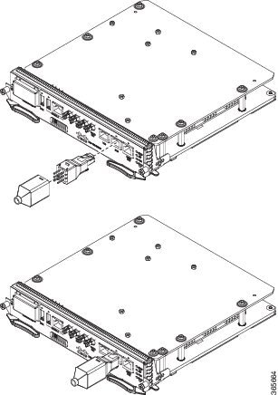
Wire Wrap Adapter Pinouts
The wire wrap adapter is used to support the wire wrap interface for the BITS port on the RSP3 module.
This adapter is plugged into the existing RJ-45 connector on the RSP3 module.
|
Wire Wrap Pin Numbers |
Signals |
|---|---|
|
1 |
RX_RING |
|
2 |
RX_TIP |
|
3 |
GND |
|
4 |
GND |
|
5 |
TX_RING |
|
6 |
TX_TIP |
GPS Port Pinout
The platform is capable of receiving or sourcing GPS signals of 1 PPS & 10 MHz. These interfaces are provided by two mini-coax 50-Ohm, 1.0/2.3 DIN series connector on the front panel. Similarly there are two mini-coax 50-Ohm connectors provided in the front panel to output this 1PPS and 10MHz.
The table below summarizes the GPS port pinouts.
|
|
10 Mhz (input and output) |
1PPS (input and output) |
|---|---|---|
|
Waveform |
Input—Sine wave Output—Square wave |
Input—Pulse shape Output—Pulse shape |
|
Amplitude |
Input— > 1.7 volt p-p(+8 to +10 dBm) Output— > 2.4 volts TTL compatible |
Input— > 2.4 volts TTL compatible Output— > 2.4 volts TTL compatible |
|
Impedance |
50 ohms |
50 ohms |
|
Pulse Width |
50% duty cycle |
26 microseconds |
|
Rise Time |
Input—AC coupled Output—5 nanoseconds |
40 nanoseconds |
Alarm Port Pinout
The table below summarizes the external alarm input pinout.
|
Pin |
Signal Name |
Description |
|---|---|---|
|
1 |
ALARM0_IN |
Alarm input 0 |
|
2 |
ALARM1_IN |
Alarm input 1 |
|
3 |
|
No connect |
|
4 |
ALARM2_IN |
Alarm input 2 |
|
5 |
ALARM3_IN |
Alarm input 3 |
|
6 |
|
No connect |
|
7 |
|
No connect |
|
8 |
COMMON |
Alarm common |
Console/Aux RJ45 RS232 Serial Port Pinout
The following table summarizes the console/aux RJ45 RS232 serial port pinout.
|
Pin |
Signal Name |
Direction |
Description |
|---|---|---|---|
|
1 |
RTS |
Not Used |
— |
|
2 |
DTR |
Not Used |
— |
|
3 |
TXD |
Output |
Transmit data |
|
4 |
RI |
Not Used |
— |
|
5 |
GND |
|
|
|
6 |
RXD |
Input |
Receive data |
|
7 |
DSR/DCD |
Not Used |
— |
|
8 |
CTS |
Not Used |
— |
T1/E1 Port Pinouts (RJ-48)
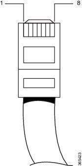
The figure below shows the RJ-48C connector wiring for the T1/E1 cable for the Cisco 2-port T1/E1-RAN interface card. The table shows the pinout configuration for the RJ-48C connectors on the Cisco 2-port T1/E1-RAN interface card for both the shielded and unshielded cables for either T1 or E1.
 Note | Cisco recommends using a shielded cable for your RJ-48C connectors. |
|
Shielded |
Unshielded |
||
|---|---|---|---|
|
Pin |
Description |
Pin |
Description |
|
1 |
Receive Ring |
1 |
Receive Ring |
|
2 |
Receive Tip |
2 |
Receive Tip |
|
3 |
Receive Shield |
3 |
|
|
4 |
Transmit Ring |
4 |
Transmit Ring |
|
5 |
Transmit Tip |
5 |
Transmit Tip |
|
6 |
Transmit Shield |
6 |
|
|
7 |
Not Used |
7 |
|
|
8 |
Not Used |
8 |
|
Management Ethernet Port Pinout
A single management copper ENET port supporting 10/100/1000Base-T operation exists on each RSP. There is no direct access to the CPU of the other RSP. It uses a standard RJ45 jack.
Note | This is not a data plane port. |
The table below summarizes the Management Ethernet port pinout.
|
Pin |
Signal Name |
Description |
|---|---|---|
|
1 |
TRP0+ |
|
|
2 |
TRP0- |
|
|
3 |
TRP1+ |
|
|
4 |
TRP1- |
|
|
5 |
TRP2+ |
|
|
6 |
TRP2- |
|
|
7 |
TRP3+ |
|
|
8 |
TRP3- |
|
USB Console Port Pinout
Two individual Type-A USB connector are used for USB console and USB mass storage. One single USB 2.0 Type-A receptacle is provided on the RSP front panel for providing console access to ROMMON, IOS-XE and diagnostics. It operates as a USB peripheral only for connection to an external host PC. This requires the use of a Type-A to Type-A connector instead of a standard USB cable.
Note | The use of the USB console is mutually exclusive with the RS232 console/Aux port. While a USB cable is inserted, access is automatically switched to this port. |
The other single USB 2.0 Type-A receptacle is provided on the RSP front panel for inserting external USB mass storage devices such as standard USB flash drives. It is used to load images, store configurations, write logs, etc. It supports operation up to 12Mbps
The table below summarizes the USB console port pinout.
|
Pin |
Signal Name |
Direction |
Description |
|---|---|---|---|
|
A1 |
Vcc |
|
+5VDC (500mA) |
|
A2 |
D- |
|
Data - |
|
A3 |
D+ |
|
Data + |
|
A4 |
Gnd |
|
Ground |
Note | The USB Console port +5VDC is input and operates as an USB peripheral device. |
USB Flash/MEM Port Pinout
The table below summarizes the USB flash/MEM port pinout.
|
Pin |
Signal Name |
Direction |
Description |
|---|---|---|---|
|
A1 |
Vcc |
|
+5VDC (500mA) |
|
A2 |
D- |
|
Data - |
|
A3 |
D+ |
|
Data + |
|
A4 |
Gnd |
|
Ground |
Note | USB TYPE-A receptacle used. |
Note | The USB flash/MEM port +5VDC is output. We provide power for USB flash/MEM, and it operates as a USB host device. |
Fiber-Optic Specifications
The specification for optical fiber transmission defines two types of fiber: single-mode and multimode. Within the single-mode category, three transmission types are defined: short reach, intermediate reach, and long reach. Within the multimode category, only short reach is available. For information about optical SFP modules, see the documentation for the SFP module at
LED Summary
The sections describe the meanings of the LEDs on the Cisco NCS 4216.
RSP LEDs
The RSP LEDs table below summarizes the RSP LEDs.
Note | A major alarm condition indicates the failure of a single fan in the fan tray; a critical alarm indicates the failure of multiple fans. In the event that a single fan fails, the Cisco NCS 4216 software adjusts the fan speed to prevent excessive heat within the chassis. |
NCS4216-RSP LED
|
LED |
Color/State |
Description (two LEDs for each port) |
|---|---|---|
|
Power (PWR) |
Off |
Disabled/no power to RSP |
|
Green |
Power rails on RSP in range |
|
|
Status (STAT) |
Off |
Disabled/power down |
|
Red |
Failure to boot (lit at reset) |
|
|
Yellow |
Rommon booted |
|
|
Green |
IOS booted and running |
|
|
Active (ACT) |
Off |
Not available |
|
Yellow |
Standby (indicates standby RSP) |
|
|
Green |
Active (indicates active RSP) |
|
|
Management port (MGMT) |
Off |
No connection |
|
Green |
Connected with no activity |
|
|
Flashing green |
Connected with activity |
|
|
Sync status (SYNC) |
Off |
Not enabled |
|
Yellow |
Free run |
|
|
Flashing yellow |
Holdover |
|
|
Green |
Locked to source |
|
|
USB flash (MEM) |
Flashing green |
USB activity |
|
BITS |
Off |
Out of service/not configured |
|
Amber |
Fault or loop condition |
|
|
Green |
In frame/working properly |
NCS4216-RSP LED Fault Condition
The PWR and STAT LEDs are available on the front panel. These LEDs provide power on the board (PWR) and overall router health (STAT) status. During power up state, these LEDs provide booting status and report errors.
Note | The digital code signing functionality validates the integrity and authenticity of the ROMMON image before booting it. |
|
PWR LED State |
STAT LED State |
Indication |
Comment |
|---|---|---|---|
|
Light Green |
Red |
Power is OK and the field-programmable gate array (FPGA) is nfigured successfully, but FPGA image validation failed. |
Image validation failed. System is in hung state. |
|
Flashing Light Green and Green alternatively |
Off |
FPGA configured and core validated successfully. FPGA image passed the control to micro-loader to boot ROMMON. |
System is up with ROMMON. Both the FPGA image is validated successfully, but the booted ROMMON (primary or secondary) is undetermined. |
|
Amber |
The digital code signing functionality reported upgrade FPGA image validation error and is continuing with the FPGA image. |
System is up with ROMMON. FPGA image is validated successfully, but the booted ROMMON (primary or secondary) is undetermined. |
|
|
Red |
The digital code signing functionality reported failure in the ROMMON image validation. |
FPGA is up but both primary and secondary ROMMON failed. System is in hung state. |
|
|
Green |
Off |
IOS is successfully booted |
IOS writes into FPGA register to indicate that it has booted, FPGA stops flashing PWR LED and turns Green. Software now controls the STAT LED. |
Interface Module LEDs
This LED summary applies to the following interface modules:
- 8x1 Gigabit Ethernet SFP + 1x10 Gigabit Ethernet SFP+ Interface Module
- OC-192 Interface Module with 8-port Low Rate CEM Interface Module (10G HO / 10G LO)
- 2-port 40 Gigabit Ethernet Interface Module (2X40GE)
- 1-port 100 Gigabit Ethernet Interface Module (1X100GE)
- 8-port 10 Gigabit Ethernet Interface Module (8X10GE))
- 48 T1/E1 TDM Interface Module (48XT1/E1)
- 48 T3/E3 TDM Interface Module (48XT3/E3)
The Status LED is Amber for the 10 Gigabit Ethernet ports when operating in WAN mode for the following IMS:
- 8x1 Gigabit Ethernet SFP + 1x10 Gigabit Ethernet SFP+ Interface Module
- OC-192 Interface Module with 8-port Low Rate CEM Interface Module (10G HO / 10G LO) Interface Module LEDs
- 48 T1/E1 and 48 T3/E3 Interface Module LEDs
- 8-port 10 Gigabit Ethernet Interface Module LEDs
- 1-port 100 Gigabit Ethernet Interface Module LEDs
- 2-port 40 Gigabit Ethernet Interface Module LEDs
OC-192 Interface Module with 8-port Low Rate CEM Interface Module (10G HO / 10G LO) Interface Module LEDs
The table below summarizes the LEDs for the OC-192 Interface Module with 8-port Low Rate CEM Interface Module (10G HO / 10G LO) interface module.
|
LED |
Color/State |
Meaning (Default=off) |
|---|---|---|
|
Power (PWR) |
Green |
All power rails are within spec |
|
Red |
Disabled |
|
|
Off |
No power to IM |
|
|
Operating Status (STAT) |
Green |
Operational |
|
Red |
Failure |
|
|
Off |
Disabled or power-down |
|
|
SFP Link (Left LED) |
Solid Green |
Link Up |
|
FLASH Green |
Link Activity |
|
|
Solid Yellow |
Fault or Error or Alarm |
|
|
FLASH Yellow |
RFU |
|
|
Off |
Disabled or No Link |
|
|
SFP Link (Right LED) |
Solid Green |
Ethernet (LAN or WAN) |
|
FLASH Green |
OTN |
|
|
Solid Yellow |
Sonet or SDH |
|
|
FLASH Yellow |
RFU |
|
|
Off |
No Link |
|
|
10G SFP+ Link (Left LED) |
Solid Green |
Link Up |
|
FLASH Green |
Link Activity |
|
|
Solid Yellow |
Fault or Error or Alarm |
|
|
FLASH Yellow |
RFU |
|
|
Off |
Disabled or No Link |
|
|
10G SFP+ Speed Mode (Right LED) |
Solid Green |
Ethernet (LAN or WAN) |
|
FLASH Green |
OTN |
|
|
Solid Yellow |
Sonet or SDH |
|
|
FLASH Yellow |
RFU |
|
|
Off |
No Link |
48 T1/E1 and 48 T3/E3 Interface Module LEDs
The table below summarizes the LEDs for the 48 T1/E1 and 48 T3/E3 interface module.
|
LED |
Color/State |
Meaning (Default=off) |
|---|---|---|
|
Power (PWR) |
Green |
All power rails are within spec |
|
Red |
Disabled |
|
|
Off |
No power to Interface Module |
|
|
Operating Status (STATUS) |
Green |
Operational |
|
FLASH green |
Booting |
|
|
Red |
Failure |
|
|
Off |
Disabled or power-down |
|
|
Port Status (PORT) |
Solid Green |
All ports are UP |
|
FLASH Green |
All ports are UP and one or more ports are in loopback |
|
|
Solid Amber |
All least one port is down |
|
|
FLASH Amber |
One or more ports are down and one or more ports are in Loopback |
|
|
Off |
All ports are disabled or shut down |
|
|
Activity Status (ACT) |
Solid Green |
Interface Module is Active |
|
FLASH Green |
Interface Module is Standby |
|
|
Off |
No link, interface module is down, disabled or shut down |
8-port 10 Gigabit Ethernet Interface Module LEDs
The table below summarizes the 8-port 10 Gigabit ethernet interface module.
|
LED |
Color/State |
Description |
|---|---|---|
|
Power (PWR) |
Green |
All power rails are within spec |
|
Red |
Disabled |
|
|
Off |
No power to Interface Module |
|
|
Operating Status (STAT) |
Red |
Failure |
|
Off |
Disabled or Power-Down |
|
|
Green |
Operational |
|
|
10G SFP+ Link (Left LED) |
Off |
Disabled or No link |
|
Yellow |
Fault or Error |
|
|
Green |
Link with no activity |
|
|
Green |
Link with activity |
|
|
10G SFP+ Speed/Mode (Right LED) |
Yellow |
10Gbps WAN |
|
Green |
10 Gbps LAN |
|
|
Alternating Yellow or Green |
10 Gbps OTN |
|
|
Off |
Disabled |
1-port 100 Gigabit Ethernet Interface Module LEDs
The table below summarizes the 1-port 100 Gigabit ethernet interface module.
|
LED |
Color/State |
Description |
|---|---|---|
|
Power (PWR) |
Green |
All power rails are within spec |
|
Red |
Disabled |
|
|
Off |
No power to Interface Module |
|
|
Operating Status (STAT) |
Red |
Failure |
|
Off |
Disabled or Power-Down |
|
|
Green |
Operational |
|
|
100G CPAK Link LED |
Off |
Disabled or No link |
|
Yellow |
Fault or Error |
|
|
Green |
Link with activity |
|
|
Green |
Link with no activity |
2-port 40 Gigabit Ethernet Interface Module LEDs
The table below summarizes the 2-port 40 Gigabit ethernet interface module.
|
LED |
Color/State |
Description |
|---|---|---|
|
Power (PWR) |
Green |
All power rails are within spec |
|
Red |
Disabled |
|
|
Off |
No power to Interface Module |
|
|
Operating Status (STAT) |
Red |
Failure |
|
Off |
Disabled or Power-Down |
|
|
Green |
Operational |
|
|
40G QSFP+ Link LED |
Off |
Disabled or No link |
|
Yellow |
Fault or Error |
|
|
Green |
Link with activity |
|
|
Green |
Link with no activity |
Power Supply LEDs
The table below summarizes the power supply LEDs for both the AC and DC power supplies.
|
LED |
Color/State |
Description |
|---|---|---|
|
Input OK |
Off |
No Input Voltage |
|
Amber |
Input voltage out of range |
|
|
Green |
Input voltage within acceptable operating range |
|
|
Output Fail |
Off |
Disabled/Forced Shut down/No input power |
|
Red |
Power supply fault (internal failure such as over temperature) |
|
|
Green |
Operational |
|
|
Blinking Red |
Output ORING FET Failed |
|
LED |
Color/State |
Description |
|---|---|---|
|
Input Power (PWR) |
Off |
No input voltage |
|
Amber |
Input voltage out of range |
|
|
Green |
Input voltage within acceptable operating range |
|
|
Status (STAT) |
Off |
Disabled/power-down/no power |
|
Red |
Power supply fault (internal failure) |
|
|
Green |
Operational |
Fan Tray LEDs
The table below summarizes the fan tray LEDs.
|
LED |
Color/State |
Description |
|---|---|---|
|
Status (TEMP) |
Off |
Disabled/power down |
|
Amber |
Over temperature |
|
|
Green |
OK |
|
|
Fan (FAN) |
Green |
Fan rotation in range |
|
Amber |
Fan fault |
|
|
Red |
Two or more fan faults |
|
|
Minor (MIN) |
Off |
No minor alarm |
|
Amber |
Minor alarm |
|
|
Major (MAJ) |
Off |
No major alarm |
|
Red |
Major alarm |
|
|
Critical (CRIT) |
Off |
No critical alarm |
|
Red |
Critical alarm (defaults to ON upon RSP reset) |
Alarm Conditions
The table below summarizes the meaning of alarm conditions on the Cisco NCS 4216.
|
Alarm Type |
Alarm Meaning |
|---|---|
|
Critical |
RSP OIR |
|
Power supply OIR |
|
|
Port in down state |
|
|
Environmental sensor threshold exceeded (voltage, temperature) |
|
|
IM OIR |
|
|
IM crash |
|
|
Major |
Standby RSP in ROMmon mode |
|
RSP removed |
|
|
RSP failure |
|
|
Info |
Port administratively shut down |
 Feedback