Business Challenge of Manual Optimization of Submarine Optical Links
During field installations, the manual optimization of submarine optical links for maximum spectral efficiency is a cumbersome and time-consuming process. The process involves a manual tuning of the line cards by searching for an optimal combination of line rates, BPS, and channel spacing.
The Cisco Automated Subsea Tuning (Cisco AST) overcomes this challenge. Cisco AST is a cloud hosted microservices-based software application. Cisco AST determines the spectral efficiency of the optical links automatically by using real time data obtained from devices at both ends of the optical link.
In a system that uses Cisco NCS 1004 devices, Cisco AST automatically tunes the NCS 1004 transponder that is connected to any DWDM line system by using real-time performance information, to optimally use the subsea cable capabilities. This tuning is done during field installation of the system and also during re-optimization of the links in future.
Cisco AST collects network data and analyses, executes the tuning algorithm, and deploys the configuration in the system.
This solution is beneficial for customers who use Cisco’s optical submarine network systems. By using Cisco AST during device installations, they can maximize their link capacity, and so reduce their operational cost.
Install Cisco AST on a Centralized Server
The Cisco AST application is delivered as a bundled tar file signed by Cisco, to ensure the authenticity of the package. The tar file contains the following files and folders:
-
A shell script (ciscoAir.sh) to install on a CentOs machine
-
A docker-compose file (docker-compose.yml) referring to the images in the local repository with a version tag
-
An images folder (images) that has images of Cisco AST microservices in a tar file with the file format tar.gz.
-
A docker-installation folder (docker_installation) that has docker-ce rpms and docker-compose installation file
-
A signature file (<PkgName>.signature)
You will receive a product information document containing the signature verification key, through eDelivery, after you purchase and download the tar file.
When it is executed with the appropriate commands, the script performs installation, start, and stop processes of the application.
Before you begin
You must have the following:
-
VM with minimum 16GB RAM, eight Core CPU with CentOs v7.6, and a storage of at least 50GB
-
Docker version 19.03.2, build 6a30dfc (The install script installs this version of docker if it is not found on the VM).
-
Docker-compose version 1.24.1, build 4667896b (The install script installs this version of docker compose if it is not found on the VM).
-
Check the firewall rules on the VM or server where you install the Cisco AST, to ensure that HTTPS port 443 is open.
The following table lists the supported browser versions:
|
Browser |
Latest Version |
Minimum Browser Version |
|---|---|---|
|
Google Chrome |
81.0.4044.122 |
72.0.3626 |
|
Mozilla Firefox |
75.0 |
68.6.0esr version |
|
Microsoft Edge |
81.0.416.64 |
44.18362.449.0 |
Procedure
| Step 1 |
To install the Cisco AST application, perform the following steps: |
| Step 2 |
To start the Cisco AST application, enter the following command: This command starts all the relevant containers. This could take up to two minutes to start the application and bring up all the services. |
| Step 3 |
Go to https://<host-name> and login to the application. |
| Step 4 |
(Optional) To stop the Cisco AST application, enter the following command: |
Cisco AST Limitations
The following limitations apply:
-
You must have root access to the server on which you install the Cisco AST application. The server infrastructure must be secure for uninterrupted functioning of the Cisco AST application.
-
You can access Cisco AST application by using only the user credentials provided during the installation. Multiple users can use the same credentials to access the application simultaneously. We recommend to store the password safely because it cannot be recovered.

Note
The user has an admin role. User credentials must be shared with only those users who will use the Cisco AST application.
-
When selecting the device pairs in a tuning project, ensure that you select only the physically connected ports of the near-end and far-end devices. Otherwise, the tuning results become unpredictable.
-
Cisco AST does not perform the gRPC Remote Procedure Call server authentication because the certificates installed on the NCS1004 devices for gRPC connection may not be uniform.
-
By default, the slot 1 is allocated for pairing the devices. Because NCS1004 has two carriers for each slot, the tuning fails if you proceed with the default number of slots. Therefore, we recommend you to select a minimum of two slots for tuning.
-
Cisco AST generates a confirmation code after you enter the authorization code when you update the license. You must enter the confirmation code in the CSSM portal. If you do not enter the confirmation code in the CSSM portal, then the confirmation information about the updated license is not stored in the CSSM portal. When you update or remove the license in the CSSM portal, it prompts you for the confirmation code again. You can locate the confirmation code which was not captured earlier, in the Technical Support Logs for entry in the CSSM portal.
-
Ensure that you do not stop or restart the Cisco AST services, while installing, updating, or returning the Cisco AST licenses. Otherwise, it may lead to unknown license reservation states and behavior.
Log into the Cisco AST Web Interface
Use this task to log into the Cisco AST web interface (Cisco AST instance).
Procedure
| Step 1 |
In the browser URL field, enter the IP address or hostname where Cisco AST is installed. The login page appears. |
||||||||||||
| Step 2 |
Enter the username and password. You must use the credentials that you chose during the installation. You can change the password later. |
||||||||||||
| Step 3 |
Click Sign In. The home page appears with the main menu in the left panel. By default, the Smart Software Licensing page is displayed. The following table describes the task you can perform in the home page.
|
||||||||||||
| Step 4 |
(Optional) To change the password, perform the following steps:
|
 icon in the bottom-left of the page and select
 Manage Licenses in Cisco AST Using Smart Licensing
Smart Licensing is a cloud-based, standardized licensing platform that simplifies and streamlines the management of your software licenses from one centralized website. For more information, see Cisco Smart Software Licensing.
Cisco AST is an offline-based licensed software application. You can use Cisco AST in evaluation mode for 90 days; this mode supports tuning of eight ports of NCS1004 devices.
Cisco AST supports only Specific License Reservation (SLR), which is an offline mode of license consumption. There are two categories of licenses.
-
Right to Use (RTU)―License to use the software.
-
Right to manage (RTM)―License to perform tuning on the ports.
You can run Cisco AST in subscription mode by purchasing and adding the following entitlements to your virtual account in Cisco Smart Software Manager (CSSM).
|
Entitlement |
Product tag |
|---|---|
|
S-OAS-AIR-LIC |
OAS Automatic Inline Retuner Software RTU |
|
S-OAS-AIR-RTM-TXP1 |
OAS Automatic Inline Retuner NCS 1004 1.2T TXP port RTM |
In order to be compliant, you must reserve one RTU license and multiple RTM licenses for each instance of the Cisco AST installation. If you have reserved only RTM licenses, but not RTU licenses, then the product becomes noncompliant.
The reserved RTM licenses are utilized for a tuning project until tuning is in progress. When you confirm the tuning result either by selecting Accept, Reject, or Revert, the RTM licenses are automatically released back to the reserved pool of licenses for that Cisco AST instance. You can reuse the released RTM licenses for other projects.
Reserve Licenses for Cisco AST
Use this task to reserve licenses for Cisco AST.
Before you begin
Procedure
| Step 1 |
Click the |
| Step 2 |
Click Reserve License. The License Reservation Request dialog box appears. |
| Step 3 |
Click Copy to Clipboard to copy the reservation code or Click Save as file to save the code to a file. |
| Step 4 |
Login to CSSM Portal using the Cisco provided username and password. |
| Step 5 |
Choose your smart account from the Virtual Account drop-down list. |
| Step 6 |
Click the License tab. |
| Step 7 |
Click License Reservation. The system displays the Smart License Reservation wizard. |
| Step 8 |
On the Enter Request Code tab, paste the reservation request code that you have generated or upload the file where the code is saved, and click Next. |
| Step 9 |
On the Select Licenses tab, check the Reserve a specific License check box. The system displays the list of surplus licenses available in your virtual account. |
| Step 10 |
Enter the number of licenses that you want to reserve for the RTU and RTM licenses, in the Reserve field. You must select at least one RTU license. |
| Step 11 |
Click Next. |
| Step 12 |
On the Review and Confirm tab, click Generate Authorization Code. The system displays the Authorization Code that is generated. |
| Step 13 |
Click Copy to Clipboard to copy the code or download it as a file. |
| Step 14 |
In the Cisco AST UI, Click Continue in the License Reservation Request dialog box. |
| Step 15 |
Click Enter Reservation Authorization Code. |
| Step 16 |
In the Enter Reservation Authorization Code dialog box, paste the authorization code, or upload the file where the authorization code is saved. |
| Step 17 |
Click Install. After successful installation, the following message appears: Authorized and Reserved |
 icon in the left panel.
Update License Reservation
When you want to reserve RTM licenses to tune more ports, you can update the reserved licenses.
Procedure
| Step 1 |
Log in to the CSSM portal using the Cisco-provided username and password. |
| Step 2 |
Click the Inventory tab. |
| Step 3 |
From the Virtual Account drop-down list, select your smart account. |
| Step 4 |
From the Product Instances tab, for the Cisco AST instance, click the Actions tab and choose Update Reserved Licenses. |
| Step 5 |
On the Select Licenses tab, check the Reserve a specific License check box, and update the number of licences. |
| Step 6 |
Click Next. |
| Step 7 |
On the Review and Confirm tab, click Generate Authorization Code. The system displays the authorization code that is generated in the Authorization Code tab. |
| Step 8 |
Click Copy to Clipboard to copy the code or download it as a file. |
| Step 9 |
Login to Cisco AST. See Log into the Cisco AST Web Interface. |
| Step 10 |
Click the |
| Step 11 |
Click Update Reservation. |
| Step 12 |
Paste the authorization code copied from the CSSM or upload the file where the code is saved. |
| Step 13 |
Click Install. After the successful installation, the following message appears:
Authorized and Reserved Cisco AST generates a confirmation code to be updated in the CSSM portal. |
| Step 14 |
Click Copy to Clipboard. |
| Step 15 |
Log in to the CSSM portal. |
| Step 16 |
Click the Inventory tab. |
| Step 17 |
From the Virtual Account drop-down list, choose your virtual account. |
| Step 18 |
Click the Product Instances tab. The list of product instances available is displayed. |
| Step 19 |
Click the required Cisco AST instance to expand the same. The Overview window is displayed. |
| Step 20 |
From the Actions drop-down list, choose Enter Confirmation Code. The Enter Confirmation code window is displayed. |
| Step 21 |
In the Reservation Confirmation Code field, paste the confirmation code. The confirmation code is updated on CSSM. |
Return Licenses
Use this task to return the license reservation for Cisco AST.
Before you begin
Procedure
| Step 1 |
Click the |
| Step 2 |
Click Return License. |
| Step 3 |
Click Continue in the Return License Conformation dialog box, to confirm. The License Reservation Return Code dialog box appears. |
| Step 4 |
Click Copy to Clipboard to copy the reservation code or click Save as file to save the code in a file. |
| Step 5 |
Log in to CSSM portal. |
| Step 6 |
Click the Inventory tab. From the Virtual Account drop-down list, select your smart account. |
| Step 7 |
In the Product Instances tab, for the Cisco AST instance, click Actions drop-down menu and choose Remove. |
| Step 8 |
When prompted, paste the return code, and click Remove product Instance. The Registration Status becomes UNIDENTIFIED in the Cisco AST user interface and the application returns back to the evaluation mode. |
Onboard Devices to Cisco AST
Cisco AST does not discover the NCS 1004 devices automatically. You must onboard the devices that need to be tuned before initiating a tuning process.
Cisco AST supports the following data rates:
-
Trunk Side: 100G, 150G, 200G, 250G, 300G, 350G, and 400G
-
Client Side: 100GE client automatic configuration only
OTU4 client requires a manual configuration.
Manage Devices
Before you begin
Procedure
| Step 1 |
To add the devices manually for onboarding, follow these steps: |
| Step 2 |
To view the device inventory, follow these steps: |
| Step 3 |
To change the device details of the onboarded device, follow these steps.
|
| Step 4 |
To delete an onboarded device, follow these steps: |
Projects
A project represents a container of the following information needed for the tuning process:
-
Devices involved in the tuning process
-
Device pairing process
-
A set of input parameters that can be adjusted to modify the tuning behavior
A project is a persistent entity. Both input parameters and tuning results are stored in the database and available for future operations.
Furthermore, the project represents a single tuning instance, and therefore parallel tuning can be performed on different project instances.
Tune Devices Using Cisco AST
|
Feature Name |
Release Information |
Feature Description |
|---|---|---|
|
Support to display margin values in the preview panel |
Cisco AST Release 2.1 |
In the Tune page, the SNR margin and Q margin values are displayed for channels that are tuned, based on the project granularity. |
|
Support for user confirmation before reading the SNR margin after channel equalization |
Cisco AST Release 2.1 |
After the tuning workflow is complete, if SNR and Q margin values are lower than the target margin value, then these values are displayed in red and the whole line item is denoted with a red dot. |
|
Support for warning message when user exceeds the bandwidth allocation |
Cisco AST Release 2.1 |
In the Properties page, when the values for parameters such as mapping granularity, start frequency, stop frequency, and so on, exceed the allocated bandwidth, an error message displays. Ensure that you enter the correct values. |
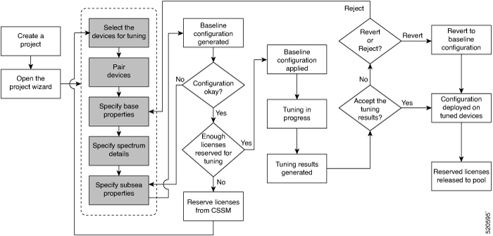
The tuning workflow is an end-to-end process that starts from creating a project and ends at verifying the final configuration for deployment. The following flow diagram depicts the tuning workflow.
 Warning |
The tuning workflow is based on a procedure that requires the power-off of the channels along the workflow and during the final configuration. This can affect the stability of the link and impact any existing channel that shares the same spectrum. |
|
Workflow Sequence |
Detailed Steps |
||
|---|---|---|---|
| Create a Project |
|
||
| Open the Project Wizard |
The project wizard opens. |
||
| Select |
Select the devices for pairing:
|
||
| Pair | Pair the near-end and far-end devices.
|
||
| Properties |
Set properties for the base configuration. For more information, see Base Configuration Properties. The default values for the properties appear.
|
||
| Spectrum |
Specify the forbidden regions of the spectrum if necessary.
The subsea configuration values that are derived from the properties are displayed. |
||
| Subsea |
Modify the subsea configuration values if needed.
|
||
|
Configuration |
If the number of licenses that are reserved is enough to tune the number of ports selected, Cisco AST proceeds with the tuning. Otherwise, you must reserve sufficient licenses and begin the tuning workflow. The tuning process begins by applying the baseline configuration. You can view the progress of the tuning process. After the tuning process is complete, you can view the tuning results. It is a set of measurements that are performed on the tuned devices after applying the configuration. |
||
|
Tune |
The upper area of the Tune page displays histogram graphs and the lower area displays a table that reports configuration and status information for each interface of the tuned devices. The histogram graphs gives a clear indication of power trends and margin distributions. Transmit power scale is displayed on the right side of the graph. Margin scale is on the left side. On the top-left corner, you have toggle buttons to switch between the variables on the horizontal and vertical axes. You can choose one of the following combinations:
The SNR margin and Q margin values are displayed for channels that are tuned based on the project granularity. Perform one of the following depending on whether you accept the tuning results:
|
||
|
Done |
The project moves to the Done state.
Click Refresh to reload the values. Click Restart to restart the tuning process from specifying the base properties. |
Project Baseline Configuration Template
The project baseline configuration template should be in the Excel sheet format containing four sheets. Ensure that you create the template in the following sheet in order to prevent warnings or errors.
-
Near-end location
-
Far-end location
-
Project Properties
-
Blocking Spectrum
You can also export the base line configuration of a successfully tuned project, which can be imported into another project. See Export Project Baseline Configuration as a Template.
Near-end and Far-end Locations
The near-end and far-end location device details are taken using the show run command executed from the device. Use the same details to fill the sheets.
The near-end location is the first sheet and the far-end location is the second sheet, and names of these sheets can differ based on locations.
The first row of the near-end and far-end location sheets should contain the device name that is onboarded already. The remaining rows of the sheets should contain the hardware module and controller configuration details. The near-end and far-end location sheets can have multiple device details.
|
Sample sheet for the Near-end Location |
|---|
|
dev2 |
|
hw-module location 0/0 |
|
mxponder |
|
trunk-rate 200G |
|
client-rate 100GE |
|
! |
|
controller Optics0/0/0/0 |
|
cd-min -1001 |
|
cd-max 1000 |
|
transmit-power 29 |
|
dwdm-carrier 100MHz-grid frequency 191.41075 |
|
bits-per-symbol 1.9375 |
|
enh-colorless-mode 3 |
|
enh-sop-tol-mode 3 |
|
nleq-comp-mode 2 |
|
cross-pol-gain-mode 4 |
|
cross-pol-weight-mode 4 |
|
cpr-win-mode 4 |
|
cpr-ext-win-mode 8 |
|
rx-voa fixed-ratio 1700 |
|
rx-voa-target-power -7 |
|
filter-roll-off-factor 0.074 |
|
! |
|
Sample sheet for the Far-end Location |
|---|
|
dev1 |
|
hw-module location 0/1 |
|
mxponder |
|
trunk-rate 200G |
|
client-rate 100GE |
|
! |
|
controller Optics0/0/0/1 |
|
cd-min -1001 |
|
cd-max 1000 |
|
transmit-power 29 |
|
dwdm-carrier 100MHz-grid frequency 191.4856 |
|
bits-per-symbol 1.9375 |
|
enh-colorless-mode 3 |
|
enh-sop-tol-mode 3 |
|
nleq-comp-mode 2 |
|
cross-pol-gain-mode 4 |
|
cross-pol-weight-mode 4 |
|
cpr-win-mode 4 |
|
cpr-ext-win-mode 8 |
|
rx-voa fixed-ratio 1700 |
|
rx-voa-target-power -7 |
|
filter-roll-off-factor 0.074 |
|
! |
Project Properties
The project properties sheet (third Excel sheet) should contain the project name and parameters with values. These parameters are mandatory. Ensure that the sheet name is Project Properties.
Note |
For Mapping granularity, the maximum value is 2. |
|
Project Name |
Test |
|---|---|
|
mappingGranularity |
2 |
|
SNRmarginTarget (dB) |
1 |
|
SNRmarginTargetTol (dB) |
0.05 |
|
StartFrequency (THz) |
191.3250 |
|
StopFrequency (THz) |
196.1250 |
|
ChannelPowerRule |
Derived |
|
Max Channel Power (dBm) |
3 |
|
Max Channel BW (GHz) |
72 |
|
OLS Add-Drop Constraints |
Limited |
|
OLS Add-Drop Module Max Output Power (dBm) |
15 |
|
Number of Ports per OLS Add-Drop Module |
8 |
|
Number Of OLS Add-Drop Module |
12 |
|
GridGranularity (GHz) |
6.25 |
|
FilteringGuardband (GHz) |
6.25 |
|
IsOpenConfigSupported |
FALSE |
Blocking Spectrum
The Blocking Spectrum, the first header row denotes the start and end positions. The following rows can have spectrum values for the start and end positions. Ensure that the sheet name is BlockingSpectrum.
|
START POSITION [THZ] |
END POSITION [THZ] |
|---|---|
|
191.3375 |
191.34375 |
|
191.34375 |
191.35 |
|
191.35 |
191.35625 |
|
191.3625 |
191.36875 |
Import Project Baseline Configuration Using Template
|
Feature Name |
Release Information |
Feature Description |
|---|---|---|
|
Import Project Baseline Configuration Using Template |
Cisco AST Release 2.1 |
You can import a project baseline configuration in Excel format (for example, project.xlsx) using a template. The Excel sheet contains near-end and far-end router details such as hardware and controller configuration, project properties, and blocking spectrum start and end positions. |
You can import a project baseline configuration using a template in the Excel format (for example, project.xlsx).
The Excel sheet contains near-end and far-end router details such as hardware and controller configuration, project properties, and blocking spectrum start and end positions.
The project base configuration parameters that are supported are:
-
Channel Power Rule
-
Max Channel Power
-
Max Channel bandwidth
-
Max Data Rate
-
SNR Margin Target
-
SNR Margin Target Tol
-
Start Frequency
-
Stop Frequency
-
Blocking Spectrum and Start Frequency
Use this task to import the project baseline configuration using an Excel template.
Before you begin
Procedure
| Step 1 |
Click Projects on the left panel. The Projects page displays. |
| Step 2 |
Click Import Project Configuration. The Import xlsx file dialog box appears. |
| Step 3 |
Click Browse and select the Excel file containing the details of the baseline configuration. |
| Step 4 |
(Optional) On the Projects page, check the Deploy Imported Baseline Configuration check box. This enables you to deploy the baseline configuration automatically on the system. |
| Step 5 |
Click Upload. The project is created in the Draft stage. |
| Step 6 |
In the Projects page, click the Project link. The project properties page displays. The values of the project properties are not editable except SNR Margin Target and SNR Margin Target Tol. Click Next. |
| Step 7 |
In the Spectrum page, Click Continue. The values of the spectrum parameters are not editable and you cannot add a new spectrum. |
| Step 8 |
In the Subsea page, Click Continue. The subsea parameters are editable. |
| Step 9 |
In the Configuration page, Click Continue & Apply. |
| Step 10 |
In the Tune page, the tuning starts. The configuration that is provided in the template is applied.
|
| Step 11 |
The project moves to the Tuned stage. |
Export Project Baseline Configuration as a Template
|
Feature Name |
Release Information |
Feature Description |
|---|---|---|
|
Export Project Baseline Configuration Using Template |
Cisco AST Release 2.1 |
You can export the baseline configuration of a successfully tuned project in the Excel format as a template. |
You can export the baseline configuration of a tuned project that is completed successfully, in the Excel format as a template, at the end of the shrinking operation. The shrinking operation is performed after you click Accept and the tuning is completed. This shrinking operation enables the channels to be put closer to each other in such a way to save space for other channels, and enhance the data capacity of the system. This Excel file can be imported into another project.
Use this task to export the project baseline configuration as an Excel template.
Before you begin
Procedure
| Step 1 |
Click Projects on the left panel. The Projects page displays. |
||
| Step 2 |
Click the name of the successfully tuned project from which you want to export the baseline configuration. |
||
| Step 3 |
Click Export Baseline Configuration. Save the baseline configuration as a template.
|
Base Configuration Properties
|
Feature Name |
Release Information |
Feature Description |
|---|---|---|
|
Support for 100G and 150G data rate |
Cisco AST Release 2.1 |
Cisco AST supports 100 and 150 Gbps for maximum line rate for optimization (max data rate). The minimum value that is supported for the max data rate parameter is reduced to 100 Gbps. |
The following table describes the various properties that you have to provide for the baseline configuration.
|
Parameter |
Description |
Minimum |
Maximum |
Default |
Unit |
||||
|---|---|---|---|---|---|---|---|---|---|
|
Channel Power Rule |
Selects the option for defining the power spectral density (PSD) at the OLS Add-Drop Module input. The available options are:
In both modes, Cisco ASTpreserves the minimum average value of PSD that must be warranted over the link during the tuning process. |
Manual, Derived |
Manual, Derived |
Derived |
N/A |
||||
|
Max Channel Power |
Maximum Channel Power of the Transponder output in dBm. |
–20 |
23 |
+3dBm |
dBm |
||||
|
Max Channel BW |
Maximum Channel BW of the Transponder in GHz. |
1 |
5000 |
72 |
GHz |
||||
|
Max Data Rate |
Maximum line rate where Cisco AST searches for optimization. If this value is equal to the Min Data Rate, the search is performed only on the selected line rate. The valid values are 100, 150, 200, 250, 300, 350, and 400. Maximum line rate depends on the choice of the minimum line rate and the mapping granularity. System Default Mode In case of the system default mode (blind mode) that uses the most reliable baseline configuration for tuning of the channels (without importing the configuration), the following options are allowed:
Imported Baseline Configuration For imported baseline configuration, the tuning is performed based on the following features:
|
100 200 2 |
400 |
300 |
Gb/s |
||||
|
Min Data Rate |
Minimum line rate where Cisco AST searches for optimization. If this value is equal to the max Data Rate, the search is performed only on the selected line rate. The valid values are 100, 150, 200, 250, 300, 350, and 400. |
200 |
400 |
200 |
Gb/s |
||||
|
SNR Margin Target |
Minimum SNR margin that must be warranted. |
0 |
20 |
1 |
dB |
||||
|
SNR Margin Target Tol |
SNR margin tolerance that limits the SNR margin target between a maximum and minimum SNR margin target range. The actual SNR margin tolerance comprises two values: Actual SNR Margin Tolerance = Input Unequalization + Measure Error. This parameter considers the maximum difference in the value of input channels PSD between any two adjacent channels that can impact the SNR margin target search. |
0 |
10.00 |
0.05 |
dB |
||||
|
Required PSD |
Minimum value of PSD that must be warranted at the OLS Add-Drop Module input in dBm/GHz. |
–40 |
–15 |
-16 |
dBm/GHz |
||||
|
Start Frequency |
Minimum frequency of the bandwidth allocated to the project. This field is mandatory. |
191.3250 |
196.1250 |
191.3250 |
THz |
||||
|
Stop Frequency |
Maximum frequency of the bandwidth allocated to the project. This field is mandatory. |
191.3250 |
196.1250 |
196.1250 |
THz |
||||
|
Blocking Spectrum N Start Frequency |
Minimum frequency of the forbidden bandwidth “N” to be used in the project. |
191.3250 |
196.1250 |
191.3250 |
THz |
||||
|
Blocking Spectrum N Stop Frequency |
Maximum frequency of the forbidden bandwidth “N” to be used in the project. |
191.3250 |
196.1250 |
191.3250 |
THz |
||||
|
Width |
Width of the Blocking Spectrum N starting from the Blocking Spectrum N Start Frequency of the forbidden bandwidth “N” to be used in the project. It is automatically derived by the tool after setting Blocking Spectrum N Start Frequency and Blocking Spectrum N Stop Frequency.
|
N/A |
N/A |
N/A |
THz |
||||
|
Mapping Granularity |
Desired resolution of the tuning spectral map. The number shows how many carriers are used as probe for the tuning. (For example, when you select the value of mapping granularity as 3, one out of three carriers is used as a probe to perform the tuning.) This parameter also affects the interpolation granularity providing a flat region for every probe used for the tuning.
|
1 |
3 |
3 |
N/A |
||||
|
OLS Add-Drop Constraints |
Selects the type of SLTE implemented and affects the baseline generation. The available options are:
|
Limited, Unlimited |
Limited, Unlimited |
Unlimited |
|||||
|
OLS Add-Drop Module Max Output Power |
Maximum Output Power of the OLS Add-Drop Module in dBm. This parameter is used in Limited mode to calculate the Maximum Number Of Ports for each OLS Add-Drop Module provisionable with the required PSD. |
–20.00 |
23.00 |
12 for Limited |
dBm |
||||
|
Number Of Ports per OLS Add-Drop Module |
Number of ports currently connected to the OLS Add-Drop Module device. This parameter is used ONLY in the Limited Mode to check if the Number Of Ports per OLS Add-Drop Module are enough to support the Required minimum required PSD at its input. If the result is higher than the Required minimum PSD, the application proceeds with the configuration; otherwise, it warns you that the Number Of Ports per OLS Add-Drop Module exceeds the maximum number compared to the worst case. The application also provides:
You can preserve the current Number Of Ports per OLS Add-Drop Module by setting the Required PSD parameter in the Manual Mode according to the value of PSD. |
1 |
150 |
12 for Limited |
N/A |
||||
|
Number Of OLS Add-Drop Module |
Number of Mux/Demux devices used to aggregate the carriers. A Filtering Guardband (GBf) is required between each of them in order to avoid any filtering impairment. |
1 |
20 |
8 for Limited |
N/A |
||||
|
Grid Granularity |
Value of the slice width of the Wavelength Selective Switch (WSS) units. The total width of any group of channels (Media Channel (MCH) or equivalent) is multiple of this parameter. |
1 |
100 |
6.25 for Limited and 12.5 GHz for Unlimited |
GHz |
||||
|
Filtering Guard band |
Value of the wasted BW due to filtering impairment at the edge of the MCH. Each MCH has one filtering guard band at each edge. (Two in total.) GBs is considered for each side. The Modulation GB (GBm) describes the value of GB that must be observed among the channels, within the same MCH. In general, GBf is ≥ 0 GHz. When carriers are combined into an MCH, the different GBs are combined to obtain the MCH required bandwidths. |
0 |
100 |
6.25 for Limited |
GHz |
Subsea Configuration Parameters
|
Feature Name |
Release Information |
Feature Description |
|---|---|---|
|
Change in default value support for Carrier Phase Recovery Window Mode (cpr-win-mode) |
Cisco AST Release 2.1 |
The default value that is supported for the Carrier Phase Recovery Window Mode is increased from 1 to 4. |
The following table explains the subsea configuration parameters.
|
Parameter |
Description |
Min |
Max |
Default |
Unit |
|---|---|---|---|---|---|
|
cd-max |
Maximum chromatic dispersion. |
–350000 |
+350000 |
+1000 |
ps/nm |
|
cd-min |
Maximum chromatic dispersion. |
–350000 |
+350000 |
–1000 |
ps/nm |
|
cpr-ext-win-mode |
Carrier phase recovery extended window mode. The range is 1–9. Choose the value depending on the number of symbols. It can support up to 288 symbols for subsea and long-haul transmission over large dispersion and large effective area fiber. |
1 |
9 |
8 |
N/A |
|
cpr-win-mode |
Carrier Phase Recovery Window Mode. The range is 1–4. Choose the value depending on the number of symbols. It can support up to 75 symbols for terrestrial regional, long-haul propagation over G.655 fiber type (small core diameter, low dispersion), or older submarine cable optimized for direct detect modulation. |
1 |
4 |
13 4 4 |
N/A |
|
cross-pol-gain-mode |
Carrier Phase Recovery Cross Polarization Gain Mode. The optimal value for subsea and long-haul transmission over large dispersion and large effective area fiber is in the range of 3–6. The optimal value for terrestrial regional, long-haul propagation over G.655 fiber type (small core diameter, low dispersion), or older submarine cable optimized for direct detect modulation, is 0. |
0 |
15 |
4 |
N/A |
|
cross-pol-weight-mode |
Carrier Phase Recovery Cross Polarization Weight Mode. The optimal value for subsea and long-haul transmission over large dispersion and large effective area fiber is in the range of 3–6. The optimal value for terrestrial regional or long-haul propagation over G.655 fiber type (small core diameter, low dispersion) or older submarine cable optimized for direct detect modulation, is in the range of 2–4. |
1 |
7 |
4 |
N/A |
|
enh-colorless-mode |
Enhanced Colorless Mode. In colorless Rx deployment, you must not set this parameter to Mode 0. The colorless interference penalty depends on many conditions; hence we recommend choosing mode 1–3 for each wavelength, by and determining the mode that provides the lowest BER. Typically, the edge channels (of a wavelength group) require only Mode 1, whereas the channels in the middle of each group need Mode 2 or 3. In Colored Rx deployment, set this parameter to Mode 0. |
1 |
3 |
3 |
N/A |
|
enh-sop-tol-mode |
Enhanced Second Order Polarization (SOP) Tolerance Mode. In subsea deployment, we recommend setting this parameter to Mode 3 for enhanced sensitivity. In subsea, the polarization state is minimal, and you can use a reduced tracking rate to improve linear sensitivity. This bit can only be enabled in Low-Power state. In terrestrial network with aerial fiber deployment, if the cable is optical ground wire (OPGW) and deployed in regions with potential lightning activity, we recommend setting this parameter to Mode 1. This setting slightly degrades back-to-back sensitivity but enables DSP to track much faster SOP events. In those types of deployments, we recommend using the highest baud rate possible and a payload rate that is less than or equal to 400G. |
1 |
3 |
3 |
N/A |
|
filter-roll-off-factor |
Root Raised Cosine (RRC) Filter Roll-Off Factor. In subsea, the goal is to maximize overall cable capacity. Therefore, you must pack as many wavelengths as you can on the fiber pair, with minimal spectral gaps between the channels. We recommend using transmitter RRC pulse shape with roll-off factor of 0.07 to 0.085. This change can be made while in high-power state. Reducing the Tx roll-off factor usually generates a small back-to -back sensitivity penalty. However, in deployment, a reduced roll-off factor reduces the effect of neighboring channel interference. |
0 |
1 |
0.074 (in steps of 0.001, length of string must be 5) |
N/A |
|
nleq-comp-mode |
Configures the nonlinear compensation functionality and optimizes best performance over propagation. For +D system with high dispersion large effective area fiber, set the value to the following value:
Similarly, for small effective area and low dispersion fiber, set the value to the following value, to provide better performance with longer distance and higher accumulated dispersion:
|
1 |
4 |
2 |
N/A |
|
rx-voa-mode |
Receive variable optical attenuation mode. The available options are:
|
fixed-ratio |
|||
|
rx-voa-fixed-ratio |
Receive Ratio of Optical Attenuation.
. |
1 |
17 |
17 |
dB |
|
rx-voa-target-power |
Receive Target Power.
|
–19 |
+3 |
–7 |
dBm |
Troubleshoot Cisco AST Issues Using Logs
You can troubleshoot any issues that you may encounter while using the Cisco AST application by reviewing the data available in the following logs:
|
Logs |
Description |
|---|---|
|
Tech-Support Logs (for issues with licensing process) |
The Smart Agent integrated with Cisco AST provides logs information regarding the licensing process.
|
|
Tuner Intermediate Logs |
You can troubleshoot the issues in a tuning project based on the tuner intermediate logs, such as the configuration data fetched and applied in the tuning process.
|
|
Audit Logs |
Audit logs display a historical record of events performed by users in the Cisco AST application.
|
|
Troubleshooting Logs |
The troubleshooting page is a centralized logging area that includes entire logs related to the services and components of a tuner project.
|
 Feedback