Table Of Contents
Provisioning Broadband Aggregators
Overview of Provisioning Broadband Aggregators
The Role or Roles of a Device on the Network
Service Profiles and Service Features
Virtual Templates and Configuration Templates
Organizing and Managing Services
Setting Up RADIUS Group Service
Setting Up Virtual Template Service
To Create Virtual Template Service
To Create L2TP Service to a LAC
To Create L2TP Service to an LNS
Setting Up Enable PPPoE Service
To Create Enable PPPoE Service
Setting Up Single VLAN Service
Setting up Network Address Translation Service
About Network Address Translation Service
To Create Network Address Translation Service
Downloading Service Profiles and Service Features
Downloading Configuration to Generic Devices
About Generic Device Configuration
To Download Configuration Commands
Deleting Service Profiles and Service Features
Provisioning Broadband Aggregators
The Cisco Broadband Access Center software enables you to provision services on broadband aggregators.
Provisioning occurs after you create administrative networks and network devices. See "Managing Devices" For information about creating administrative networks and network devices.
Table 7-1 Provisioning Broadband Aggregators Topics
If you want to... Go to the...Learn about provisioning broadband aggregators
Add service profiles and service features to a broadband aggregator
Manage service profiles and service features, including selecting a method of downloading configuration information
"Downloading Service Profiles and Service Features" section.
Overview of Provisioning Broadband Aggregators
From the Network tab, you can provision the Cisco IOS devices that act as broadband aggregators on your network. Before you begin to provision broadband aggregators, you should understand:
•The role or roles that a device plays on a network
•Encapsulation methods on a network
•Service profiles and features
•Virtual templates and configuration templates
The Role or Roles of a Device on the Network
You can configure Cisco broadband aggregators with the roles defined in Table 7-2.
Encapsulation Methods
The encapsulation method for a broadband aggregator depends upon its role in the network:
•If it is a LAC, you can configure one of the following PPP encapsulation types:
–PPP over ATM (PPPoA)
–PPP over Ethernet over ATM (PPPoEoA)
–PPP over Ethernet over Ethernet (PPPoEoE)
–PPP over Ethernet over VLAN (PPPoEoVLAN)
•If it is a PTA, you can configure the following encapsulation types:
–All of the PPP encapsulation types also available to a LAC or an LNS
–Routed bridge encapsulation (RBE)
Note With a PTA using a PPP encapsulation type, authentication occurs at the service provider using a local database or a AAA server. RBE users are not authenticated and, instead, are routed directly to the Internet.
Figure 7-1 illustrates encapsulation for a LAC/LNS network.
Figure 7-1 Encapsulation in the LAC/LNS Network Model
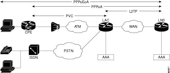
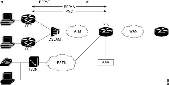
Figure 7-2 illustrates encapsulation for a PTA network.
Figure 7-2 Encapsulation in the PTA Network Model
Service Profiles and Service Features
Once you determine the role that a device plays on your network and what encapsulation method it supports, you identify the service profiles and service features with which to provision it. Table 7-3 defines what a service profile is and what a service feature is.
Virtual Templates and Configuration Templates
BAC supports two types of templates:
•Cisco IOS virtual templates—A virtual template is a logical entity that you configure on routers and dynamically apply to virtual access interfaces. A virtual template provides generic configuration on an as-needed basis to a virtual interface. For more information, see Cisco IOS documentation.
•BAC configuration templates—A configuration template contains the Cisco IOS commands, attributes, and variables that define a service feature. A configuration template defines variables and merges variables with data to generate commands that you download to a router. You can use the default configuration templates supplied with BAC, or you can define your own templates. Use the Show Template action button to view the template. For information about customizing BAC templates, see "Customizing Broadband Access Center."
Note In the Web UI, BAC displays default values for many attributes that it derives from the configuration templates.
Organizing and Managing Services
Routers perform single or multiple roles in a broadband aggregation network, depending on the services with which you configure them. Organizing and managing services involves the following procedures.
1. Adding a service profile.
2. Adding the Basic service feature to the service profile.
3. Optionally, adding additional service features to the service profile.
4. Repeating 1 through 3 for each role that a router performs.
A service profile describes the role and the encapsulation type of a broadband aggregator. A service feature is comparable to a Cisco IOS configlet, which consists only of the commands necessary to modify the router's current configuration to enable a particular service.
About Service Profiles
Selecting a service profile determines the service features that you can configure on a router. Table 7-4 summarizes the service features available with each service profile:
About Service Features
The service features that you download to a router become part of its running configuration. Table 7-5 provides an overview of all the service features.
Note You can customize any BAC service feature using Template Manager. For more information, see "Customizing Broadband Access Center."
To Add a Service Profile
To add a service profile, follow these steps:
Step 1 Log in to BAC.
Step 2 Click the Network tab. The system displays the Administrative Network Management page in the main window.
Step 3 In the Object Selector, select the network where the device is located.
Step 4 In the subtask bar, click Device Management. The system displays the Device Management page in the main window.
Step 5 On the Device Management page, select the device to which you want to add a service profile.
Step 6 Click Add Service. The system displays the Service Profile Selection page.
Step 7 Select the service that you want to add; for example, select PTAPPPoEoA.
Step 8 Click Next. The system displays the Service Feature Selection page.
Step 9 Begin to add service features. At a minimum, you must add Basic service. For more information, see "Setting Up Basic Service" section.
The next sections of this chapter provided detailed procedures for adding each of the service features.
Setting Up Basic Service
Set up Basic service to define the basic configuration of a router.
About Basic Service
When you add Basic service, you define the fields listed in Table 7-6.
To Create Basic Service
To create Basic service, complete the procedure described in "To Add a Service Profile" section and then follow these steps:
Step 1 On the Service Feature Selection page, select Basic and click Next. The system displays the Service Feature Data page.
Step 2 In the Service Feature Data page, enter the Basic service information, as defined in Table 7-6.
Step 3 Optionally, click Download Method to select a method of download the running configuration. The system displays the Subscriber Provisioning - Device Configuration Download dialog box. For more information, see "Downloading Service Profiles and Service Features" section.
Step 4 If desired, click one of the following action buttons:
•Reset Values—Restores the default values.
•Config Preview—Displays the configuration that BAC generates based on what you have entered.
•Show XML—Displays the user interface components corresponding to the template variables for the service feature data that you have entered.
•Show Template—Displays the provisioning template.
Step 5 Click Next to download the configuration. The system displays the Configuration Download Status box.
Step 6 Click Finish.
Setting Up RADIUS Service
Set up RADIUS service to identify the AAA server that you want to use for authentication and authorization.
About RADIUS Service
When you add RADIUS service, you define the fields listed in Table 7-7.
To Create RADIUS Service
To create RADIUS service, follow these steps:
Step 1 On the Service Feature Selection page, select Radius and click Next. The system displays the Service Feature Data page.
Step 2 If necessary, in the Select a Service Feature drop-down list box, select RADIUS. The system displays the Device Provisioning-Service Feature Data page in the content area of the main window.
Note You need to select RADIUS from the drop-down list, if you selected RADIUS along with one or more other service features on the Service Feature Selection page.
Step 3 Click Add. The system displays the Device Provisioning-Service Feature Data dialog box.
Step 4 In the Device Provisioning-Service Feature Data dialog box, enter the RADIUS service information, as defined in Table 7-7.
Step 5 When you are done, click OK. The system redisplays the Service Feature Data page.
Step 6 Click Download Method to select a method of download the running configuration. The system displays the Subscriber Provisioning - Device Configuration Download dialog box. For more information see "Downloading Service Profiles and Service Features" section.
Step 7 Click Next to begin downloading the configuration. The system displays the Configuration Download Status box.
Step 8 Click Finish.
Setting Up RADIUS Group Service
Set up RADIUS group service to enable round-robin use of multiple, local AAA servers.
About RADIUS Groups
When you add RADIUS Group service, you define the fields listed in Table 7-8.
Note You must set up RADIUS service before you set up RADIUS Group service.
To Create RADIUS Group
To create RADIUS Group service, follow these steps:
Step 1 On the Service Feature Selection page, select Radius Group and click Next. The system displays the Service Feature Data page.
Step 2 If necessary, in the Select a Service Feature drop-down list box, select Radius Group. The system displays the Device Provisioning-Service Feature Data in the content area of the main window.
Note If you selected RADIUS Group along with one or more other service features on the Service Feature Selection page, you need to select Radius Group in the Select a Service Feature drop-down list box.
Step 3 Click Add. The system displays the Device Provisioning-Service Feature Data dialog box, which is superimposed over the main window.
Step 4 In the Device Provisioning-Service Feature Data dialog box, enter the RADIUS Group service information, as defined in Table 7-7.
Step 5 When you are done, click OK. The system redisplays the Service Feature Data page.
Step 6 Click Next to begin downloading the configuration. The system displays the Configuration Download Status box.
Step 7 Click Finish.
Setting Up IP Pool Service
Set up IP Pool service to define the pool of local IP addresses available to the router.
About IP Pools
When you add IP Pool service, you define the fields listed in Table 7-9.
Table 7-9 IP Pool Service Field
field DescriptionPool Name
The name of the IP address pool.
IP From
The starting address of the IP Pool.
IP To
The ending address of the IP Pool.
To Create IP Pool Service
To create IP Pool service, follow these steps:
Step 1 On the Service Feature Selection page, select IP Pool and click Next. The system displays the Service Feature Data page.
Step 2 If necessary, in the Select a Service Feature drop-down list box, select IP Pool. The system displays the Device Provisioning-Service Feature Data in the content area of the main window.
Note If you selected IP Pool along with one or more other service features on the Service Feature Selection page, you need to select IP Pool in the Select a Service Feature drop-down list box.
Step 3 In the Device Provisioning-Service Feature Data dialog box, enter the IP Pool information, as defined in Table 7-9.
Step 4 Click Add. The system displays the Device Provisioning-Service Feature Data dialog box, which is superimposed over the main window.
Step 5 Click Next to begin downloading the configuration. The system displays the Configuration Download Status box.
Step 6 Click Finish.
Setting Up DHCP Service
Set up DHCP service to define the IP address of the DHCP server you use for IP address assignment.
About DHCP Service
When you add DHCP service, you define the field listed in Table 7-10.
Table 7-10 DHCP Service FIelds
Field DescriptionDHCP Server IP
The IP address of the DHCP server that you want to use for dynamic address assignment.
To Create DHCP Service
To create DHCP service, follow these steps:
Step 1 On the Service Feature Selection page, select DHCP and click Next. The system displays the Service Feature Data page.
Step 2 If necessary, in the Select a Service Feature drop-down list box, select DHCP. The system displays the Device Provisioning-Service Feature Data in the content area of the main window.
Note If you selected DHCP along with one or more other service features on the Service Feature Selection page, you need to select DHCP in the Select a Service Feature drop-down list box.
Step 3 Click Add. The system displays the Device Provisioning-Service Feature Data dialog box, which is superimposed over the main window.
Step 4 In the Device Provisioning-Service Feature Data dialog box, enter the DHCP service information, as defined in Table 7-7.
Step 5 When you are done, click OK.
Step 6 Click Next to begin downloading the configuration. The system displays the Configuration Download Status box.
Step 7 Click Finish.
Setting Up Virtual Template Service
Set up Virtual Template service to provide generic configuration on an as-needed basis to a virtual interface on a router. Virtual Template service is available only in LACPPPoA and PTAPPPoA environments.
About Virtual Templates
When you add Virtual Template service, you define the fields listed in Table 7-11.
To Create Virtual Template Service
To create Virtual Template service, follow these steps:
Step 1 On the Service Feature Selection page, select Virtual Template and click Next. The system displays the Service Feature Data page.
Step 2 If necessary, in the Select a Service Feature drop-down list box, select Virtual Template. The system displays the Device Provisioning-Service Feature Data in the content area of the main window.
Note If you selected Virtual Template, along with one or more other service features on the Service Feature Selection page, you need to select Virtual Template in the Select a Service Feature drop-down list box.
Step 3 Click Add. The system displays the Device Provisioning-Service Feature Data dialog box, which is superimposed over the main window.
Step 4 In the Device Provisioning-Service Feature Data dialog box, enter the Virtual Template service information, as defined in Table 7-11.
Step 5 When you are done, click OK. The system redisplays the Service Feature Data window.
Step 6 Click Next to begin downloading the configuration. The system displays the Configuration Download Status box.
Step 7 Click Finish.
Setting Up PVC Range Service
Set up PVC Range service to provision a range of PVCs on an ATM subinterface. You can group a number of PVCs on a multipoint ATM subinterface and simplify their configurations.
Note In LACPPPoA and PTAPPPoA environments, this service is called PVCRangeoA.
About PVC Range Service
When you add PVC Range service for LAC and PTA service profiles, you define the fields listed in Table 7-12.
Note For more detailed information about configuring PVC ranges, see the Cisco IOS documentation which describes ATM PVC range and Routed Bridge Encapsulation subinterface grouping.
When you add PVC Range service for an RBE service profile, you define the properties in listed in Table 7-13.
To Create PVC Range Service
To create PVC Range service, follow these steps:
Step 1 On the Service Feature Selection page, select PVC Range and click Next. The system displays the Service Feature Data page.
Step 2 If necessary, in the Select a Service Feature drop-down list box, select PVC Range. The system displays the Device Provisioning-Service Feature Data in the content area of the main window.
Note If you selected PVC Range along with one or more other service features on the Service Feature Selection page, you need to select PVC Range in the Select a Service Feature drop-down list box.
Step 3 Click Add. The system displays the Device Provisioning-Service Feature Data dialog box, which is superimposed over the main window.
Step 4 In the Device Provisioning-Service Feature Data dialog box, enter the PVC service data. If you are adding PVC range service to a LAC or PTA profile, see Table 7-12. If you are adding PVC range service to an RBE profile, see Table 7-13.
Step 5 When you are done, click OK. The system redisplays the Service Feature Data window.
Step 6 Click Next to begin downloading the configuration. The system displays the Configuration Download Status box.
Step 7 Click Finish.
Setting Up Single PVC Service
Set up Single PVC service to provision single PVCs on ATM and RBE subinterface.
Note In LACPPPoA and PTAPPPoA environments, this service is called SinglePVCoA.
About Single PVC Service
When you add Single PVC service for LAC and PTA service profiles, you define the fields listed in Table 7-14.
When you add PVC Range service for an RBE service profile, you define the fields in listed in Table 7-15.
To Create Single PVC Service
To create Single PVC service, follow these steps:
Step 1 On the Service Feature Selection page, select Single PVC and click Next. The system displays the Service Feature Data page.
Step 2 If necessary, in the Select a Service Feature drop-down list box, select Single PVC. The system displays the Device Provisioning-Service Feature Data in the content area of the main window.
Note If you selected Single PVC along with one or more other service features on the Service Feature Selection page, you need to select Single PVC in the Select a Service Feature drop-down list box.
Step 3 Click Add. The system displays the Device Provisioning-Service Feature Data dialog box, which is superimposed over the main window.
Step 4 In the Device Provisioning-Service Feature Data dialog box, enter the PVC service information. To create Single PVC service for a LAC or PTA profile, see Table 7-14. To create PVC service for an RBE profile, see Table 7-15.
Step 5 When you are done, click OK. The system redisplays the Service Feature Data window.
Step 6 Click Next to begin downloading the configuration. The system displays the Configuration Download Status box.
Step 7 Click Finish. The system redisplays the Device Management page.
Setting Up L2TP Service
Set up L2TP service to specifies the LAC and LNS that use a specified the Layer 2 tunnel. The properties differ depending on which profile you select.
About L2TP Service to a LAC
When you select one of the LAC profiles, you define the L2TP fields listed in Table 7-16.
To Create L2TP Service to a LAC
To create L2TP service to a LAC, make sure that you have selected one of the LAC service profiles. Then, follow these steps:
Step 1 On the Service Feature Selection page, select L2TP and click Next. The system displays the Service Feature Data page.
Step 2 If necessary, in the Select a Service Feature drop-down list box, select L2TP. The system displays the Device Provisioning-Service Feature Data in the content area of the main window.
Note If you selected L2TP along with one or more other service features on the Service Feature Selection page, you need to select L2TP in the Select a Service Feature drop-down list box.
Step 3 Click Add. The system displays the Device Provisioning-Service Feature Data dialog box, which is superimposed over the main window
Step 4 In the Device Provisioning-Service Feature Data dialog box, enter the L2TP service information, as defined in Table 7-16.
Step 5 When you are done, click OK. The system redisplays the Service Feature Data window.
Step 6 Click Next to begin downloading the configuration. The system displays the Configuration Download Status box.
Step 7 Click Finish.
About L2TP Service to an LNS
When you select the LNS service profile, you define the L2TP fields listed in Table 7-17.
To Create L2TP Service to an LNS
To create L2TP service to an LNS, make sure that you have selected one of the LNS service profiles. Then, follow these steps:
Step 1 On the Service Feature Selection page, select L2TP and click Next. The system displays the Service Feature Data page.
Step 2 If necessary, in the Select a Service Feature drop-down list box, select L2TP. The system displays the Device Provisioning-Service Feature Data in the content area of the main window.
Note If you selected L2TP along with one or more other service features on the Service Feature Selection page, you need to select L2TP in the Select a Service Feature drop-down list box.
Step 3 Click Add. The system displays the Device Provisioning-Service Feature Data dialog box, which is superimposed over the main window.
Step 4 In the Device Provisioning-Service Feature Data dialog box, enter the L2TP service information, as described in Table 7-17.
Step 5 When you are done, click OK. The system redisplays the Service Feature Data window.
Step 6 Click Next to begin downloading the configuration. The system displays the Configuration Download Status box.
Step 7 Click Finish.
Setting Up Enable PPPoE Service
Set up Enable PPPoE service so that you can enable or disable PPPoE on an ethernet interface.
About Enable PPPoE Service
When you add EnablePPPoE service, you define the field listed in Table 7-18.
Table 7-18 Enable PPPoE Service Field
Field DescriptionSubscriber-facing Interface Selector
The subscriber-facing interface on the broadband aggregator that you want to enable.
To Create Enable PPPoE Service
To create Enable PPPoE service, follow these steps:
Step 1 On the Service Feature Selection page, select EnablePPPoE and click Next. The system displays the Service Feature Data page.
Step 2 If necessary, in the Select a Service Feature drop-down list box, select EnablePPPoE. The system displays the Device Provisioning-Service Feature Data in the content area of the main window.
Note If you selected EnablePPPoE along with one or more other service features on the Service Feature Selection page, you need to select EnablePPPoE in the Select a Service Feature drop-down list box.
Step 3 Click Add. The system displays the Device Provisioning-Service Feature Data dialog box, which is superimposed over the main window.
Step 4 In the Device Provisioning-Service Feature Data dialog box, do the following:
a. In the Subscriber-facing Interface Selector field, enter the value for the subscriber-facing module that this PVC uses; or, to browse for the interface, click Select. The system displays the Popup Selection window.
b. Select the interface, expanding the interface hierarchy as needed, and click Select. The system redisplays the Device Provisioning-Service Feature Data dialog box.
Step 5 When you are done, click OK. The system redisplays the Service Feature Data page.
Step 6 Click Next to begin downloading the configuration. The system displays the Configuration Download Status box.
Step 7 Click Finish. The system redisplays the Device Management page.
Setting Up VPDN Service
Set up VPDN service to enables virtual private dialup networking on a router.
About VPDN Service
When you create VPDN service, you define the fields listed in Table 7-19.
To Create VPDN Service
To create VPDN service, follow these steps:
Step 1 On the Service Feature Selection page, select VPDN and click Next. The system displays the Service Feature Data page.
Step 2 If necessary, in the Select a Service Feature drop-down list box, select VPDN. The system displays the Device Provisioning-Service Feature Data in the content area of the main window.
Note If you selected VPDN along with one or more other service features on the Service Feature Selection page, you need to select VPDN in the Select a Service Feature drop-down list box.
Step 3 Click Add. The system displays the Device Provisioning-Service Feature Data dialog box, which is superimposed over the main window.
Step 4 In the Device Provisioning-Service Feature Data dialog box, enter the VPDN service information, as defined in Table 7-19.
Step 5 When you are done, click OK. The system redisplays the Service Feature Data window.
Step 6 Click Next to begin downloading the configuration. The system displays the Configuration Download Status box.
Step 7 Click Finish.
Setting Up VLAN Range Service
Set up VLAN range service to provision multiple Ethernet virtual LAN subinterfaces.
Note If you try download VLAN Range service to a device using HTTP, the Cisco IOS software generates an error message. Download VLAN Range service using Telnet, instead.
About VLAN Range Service
When you add VLAN Range service, you define the fields listed in Table 7-20.
Note If you attempt to download a VLAN range using either Telnet, Cisco IOS reports an error. The other download methods operate properly.
To Create VLAN Range Service
To create VLAN Range service, follow these steps:
Step 1 On the Service Feature Selection page, select VLAN Range and click Next. The system displays the Service Feature Data page.
Step 2 If necessary, in the Select a Service Feature drop-down list box, select VLAN. The system displays the Device Provisioning-Service Feature Data in the content area of the main window.
Note If you selected VLAN Range along with one or more other service features on the Service Feature Selection page, you need to select VLAN Range in the Select a Service Feature drop-down list box.
Step 3 Click Add. The system displays the Device Provisioning-Service Feature Data dialog box, which is superimposed over the main window.
Step 4 In the Device Provisioning-Service Feature Data dialog box, enter the VLAN Range service information, as defined in Table 7-20.
Step 5 When you are done, click OK. The system redisplays the Service Feature Data window.
Step 6 Click Next to begin downloading the configuration. The system displays the Configuration Download Status box.
Step 7 Click Finish.
Setting Up Single VLAN Service
Set up Single VLAN service to enable provisioning a single Ethernet virtual LAN subinterface.
About Single VLAN Service
When you add Single VLAN service, you define the fields listed in Table 7-21.
To Create Single VLAN Service
To create Single VLAN service, follow these steps:
Step 1 On the Service Feature Selection page, select Single VLAN and click Next. The system displays the Service Feature Data page.
Step 2 If necessary, in the Select a Service Feature drop-down list box, select Single VLAN. The system displays the Device Provisioning-Service Feature Data in the content area of the main window.
Note If you selected Single VLAN along with one or more other service features on the Service Feature Selection page, you need to select Single VLAN in the Select a Service Feature drop-down list box.
Step 3 Click Add. The system displays the Device Provisioning-Service Feature Data dialog box, which is superimposed over the main window.
Step 4 In the Device Provisioning-Service Feature Data dialog box, enter the Single VLAN service information, as defined in Table 7-21.
Step 5 When you are done, click OK. The system redisplays the Service Feature Data window.
Step 6 Click Next to begin downloading the configuration. The system displays the Configuration Download Status box.
Step 7 Click Finish.
Setting up Network Address Translation Service
Set up Network Address Translation (NAT) service to enable NAT if you have implemented private IP address space.
About Network Address Translation Service
When you add NAT service, you define the fields listed in Table 7-22.
To Create Network Address Translation Service
To create NAT service, follow these steps:
Step 1 On the Service Feature Selection page, select NAT and click Next. The system displays the Service Feature Data page.
Step 2 In the Select a Service Feature drop-down list box, select NAT. The system displays the Service Feature Data Page.
Note If you selected NAT along with one or more other service features on the Service Feature Selection page, you need to select NAT in the Select a Service Feature drop-down list box.
Step 3 Click Add. The system displays the Device Provisioning-Service Feature Data dialog box, which is superimposed over the main window.
Step 4 In the Device Provisioning-Service Feature Data dialog box, enter the NAT service information, as defined in Table 7-22.
Step 5 When you are done, click OK. The system redisplays the Service Feature Data page.
Step 6 Click Next to begin downloading the configuration. The system displays the Configuration Download Status box.
Step 7 Click Finish.
Setting Up Policy Service
BAC enables you to apply QoS policy maps to a router through Policy service. Policy maps define QoS actions and rules. You create them as network resources using the Network Services tab. For more information, see "Managing Network Services."
About Policy Service
When you add Policy service, you define the fields listed in Table 7-23.
Table 7-23 Policy Service Fields
Field DescriptionPolicy Map Name
The name of the policy map that you want to apply to a router.
Description
An optional text block.
To Create Policy Service
To create Policy service, follow these steps:
Step 1 From the Service Profile Selection page, select Policy and click Next. The system displays the Service Feature Selection page in the content area of the main window.
Step 2 On the Service Feature Selection page, check Policy and click Next. The system displays the Service Feature Data page.
Step 3 If necessary, in the Select a Service Feature drop-down list box, select Policy. The system displays the Device Provisioning-Service Feature Data page.
Step 4 Click Add. The system displays the Device Provisioning-Service Feature dialog box.
Step 5 In the Device Provisioning-Service Feature Data dialog box, enter the Policy service information, as defined in Table 7-23.
Step 6 When you are done, click OK. The system redisplays the Service Feature Data page.
Step 7 Click Next to begin downloading the configuration. The system displays the Configuration Download Status box.
Step 8 Click Finish.
Setting Up Route Map Service
You set up Route Map service to enable policy routing and redistribution of routing information.
About Route Map Service
When you add Route Map service, you define the fields listed in Table 7-23.
To Create Route Map Service
To create Route Map service, follow these steps:
Step 1 From the Service Profile Selection page, select Policy and click Next. The system displays the Service Feature Selection page in the content area of the main window.
Step 2 On the Service Feature Selection page, check Route Map and click Next. The system displays the Service Feature Data page.
Step 3 If necessary, in the Select a Service Feature drop-down list box, select Route Map. The system displays the Device Provisioning-Service Feature Data page.
Step 4 Click Add. The system displays the Device Provisioning-Service Feature dialog box.
Step 5 In the Device Provisioning-Service Feature Data dialog box, enter the Route Map service information, as defined in Table 7-24.
Step 6 When you are done, click OK. The system redisplays the Service Feature Data page.
Step 7 Click Next to begin downloading the configuration. The system displays the Configuration Download Status box.
Step 8 Click Finish.
Downloading Service Profiles and Service Features
BAC enables you to select from among several methods of downloading configuration files to your network devices.
About Download Methods
Select a download method from the options listed in Table 7-25.
To Choose a Download Method
To choose a download method, follow these steps:
Step 1 Display the Service Feature Data page in the main window.
Step 2 Click Download Method. The system displays the Device Provisioning-Device Configuration Download dialog box.
Step 3 Select one of the methods for downloading.
Step 4 In the SSH Type drop-down list box, enable or disable security encryption by selecting one of the following:
•None—To download the information without encryption.
•des—To download the information using the Data Encryption Standard (DES) algorithm.
•3des—To download the information using the stronger Triple DES (3DES) algorithm.
Step 5 In the Destination drop-down list box, select one of the following:
•Running Config—downloads the configuration information only to the running configuration file on the router.
•Running Config & Copy to Startup—downloads the configuration to the running configuration file and then copies the configuration to the start up configuration file. When you need to restart this router, the configuration is copied from the start up file to the running file.
Step 6 Click OK.
Downloading Configuration to Generic Devices
BAC enables you to download text files containing Cisco IOS configuration commands to generic devices. You cannot provision generic devices with services and BAC templates are unavailable for them. You might use a text file to download commands to a device in the following scenarios:
•You want BAC to know about the device, although it plays no role in provisioning.
•You want to maintain a basic configuration start up script that you can quickly download to a device that has failed.
About Generic Device Configuration
When you download configuration commands to a generic device, you set the fields listed in Table 7-26.
Table 7-26 Generic Device Configuration Fields
Field DescriptionDownload Method
Sets the method you use to download. For more information, see the "About Download Methods" section.
Port Number
Sets the console port number to use when downloading, if you select the console port method. This field is not displayed with the other download options.
Destination
Determines whether this file is downloaded to the running configuration file only of the router, or downloaded to running configuration and then copied to the startup configuration file.
To Download Configuration Commands
To download configuration commands to a generic device, follow these steps:
Step 1 In a text editor, create the configuration file.
Step 2 Log in to BAC and click the Network tab. The system displays the Administrative Network Management page in the content area of the main window.
Step 3 In the Object Selector, select the network where the device is located.
Step 4 In the subtask bar, click Device Management. The system displays the Device Management page in the main window.
Step 5 On the Device Management page, select the generic device to which you want to download configuration commands.
Step 6 Click Download Configuration. The system displays the Device Configuration Selection page in the main window. In the Device Field, it displays the path to the device.
Step 7 Click Browse to select the configuration file that you want to download.
Step 8 Click Next. The system displays the Device Configuration Download page in the main window.
Step 9 In the Device Configuration Download page, enter the download information as defined in Table 7-26.
Step 10 Click Next. The system displays the Device Configuration Status page in the main window.
Step 11 Click Finish.
Deleting Service Profiles and Service Features
To delete a service profile or a service feature from a router, follow these steps:
Step 1 Click the Network tab. The system displays the Administrative Network Management page in the main window.
Step 2 In the Object Selector, select the network where the device is located.
Step 3 In the subtask bar, click Device Management. The system displays the Device Management page in the main window.
Step 4 On the Device Management page, select the device from which you want to delete a service feature.
Step 5 Click Delete Service. The system displays the Existing Role Selection page.
Step 6 Under Device Un-Provisioning - Existing Roles, click the icon for the role.
Step 7 Click Next. The system displays the Service Feature Selection page.
Step 8 Check the feature or features that you want to delete.
Note To remove a service profile from a router, you must delete all service features you have assigned to the profile. Deleting the service features, removes the service profile from the router.
Step 9 Click Next. The system displays the Service Feature Data page.
Step 10 From the Select A Service Feature drop-down list box, select the feature that you want to delete.
Step 11 Click Next.