Operating the Appliance
Available Languages
Table Of Contents
Identifying External Components and Connectors
Troubleshooting Hardware Problems
Using LEDs to Identify Problems
Operating the Appliance
This chapter describes how to identify the components and other hardware features of the
Cisco 8300 Series AON Appliance. It also provides information to help you troubleshoot hardware problems. It contains the following sections:•
Bringing the Appliance Online
•

Note
Bringing the Appliance Online
Once you have installed the Cisco 8300 Series AON Appliance in a rack, use the sections that follow to complete the installation and bring the appliance online:
•
Identifying External Components and Connectors
Figure 3-1 shows the indicators and controls on the front panel of the appliance.
Figure 3-1 Front Panel
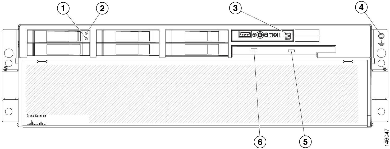
Figure 3-2 shows the indicators on the operator information panel located on the front of the appliance.
Figure 3-2 Operator Information Panel
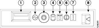
Figure 3-3 shows the I/O and power connectors on the rear panel of the appliance.
Figure 3-3 Rear Panel I/O and Power Connectors
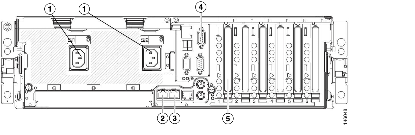
Power supplies
Console serial port
Gigabit Ethernet 1
Gigabit Ethernet 3
Gigabit Ethernet 2
Note
Connecting to AC Power
Connect the each of the appliance's two power supplies to a 15 A, 120 VAC (10 A, 240 VAC) circuit with overcurrent protection.

Warning
Connecting to a Network
The Cisco 8300 Series AON Appliance has three Gigabit Ethernet connections. Connect an RJ-45 cable to Gigabit Ethernet 1.
Note
Connecting a Serial Cable
The appliance has a serial console port (RJ-45). Depending on the cable and the adapter used, this port appears as a DTE or DCE device at the end of the cable.
For connection to a PC running terminal emulation software, use the RJ-45 to DB-9 adapter cable that shipped with your appliance. Connect the included serial cable to the appropriate port, as shown in Figure 3-3. Then configure your terminal application with the following settings:
•
•
•
•
Note
Where to Go Next
See the following documents to complete the configuration of the Cisco 8300 Series AON Appliance:
•
•
See the "Obtaining Documentation" section on page xi for information on how to obtain documentation.
Troubleshooting Hardware Problems
Use Light Path Diagnostics to diagnose system errors. The Light Path Diagnostics panel is inside the operator information panel, on the right front of the appliance (see Figure 3-1). To access the Light Path Diagnostics panel, slide the latch to the left on the front of the Light Path Diagnostics drawer.
Figure 3-4 shows the controls and LEDs on the Light Path Diagnostics panel.
Figure 3-4 Light Path Diagnostics Panel
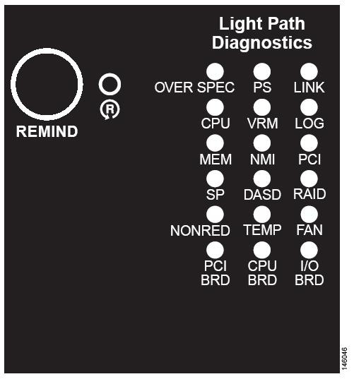
To acknowledge a system error but not take immediate action, press the Remind button and place Light Path Diagnostics in remind mode. When the appliance is in remind mode, the system-error LED on the front of the appliance flashes. If a new failure occurs, the system-error LED is lit again.
Press the Reset button to reset the appliance and run the power-on self-test (POST). You might have to use a pen or the end of a straightened paper clip to press the button.
The appliance is designed so that LEDs remain lit when the appliance is connected to an AC power source but is not turned on, provided that the power supply is operating correctly. This feature helps you to isolate the problem when the operating system is shut down.
Any memory, microprocessor, and VRM LED can be lit again without AC power after you remove the microprocessor tray so that you can isolate a problem. After AC power has been removed from the appliance, power remains available to these LEDs for up to 24 hours.
To view the memory, microprocessor, and VRM LEDs, press and hold the Light Path Diagnostics button on the memory card or microprocessor board to light the error LEDs. The LEDs that were lit while the appliance was running will be lit again while the button is pressed.
Using LEDs to Identify Problems
LEDs in three locations on the appliance are available to help you diagnose problems that might occur during installation and operation of the Cisco 8300 Series AON Appliance. Use them in the following order:
1.
2.
3.
Note
Table 3-1 describes the LED indicators on the Light Path Diagnostics panel.
Table 3-1 Light Path Diagnostics Panel
OVERSPEC
There is insufficient power to power the system. NON RED and LOG might also be lit.
PS
A power supply has failed or has been removed.
Note
LINK
Not used.
CPU
A CPU has failed, is missing, or has been improperly installed. Contact your Cisco support representative.
VRM
A voltage regulator module has failed or is missing.
LOG
Not used.
MEM
A memory module has failed. The error LED on the memory card should also be lit.
NMI
A hardware error has occurred. The PCI or MEM LED may also be lit.
PCI
Not used.
SP
Not used.
DASD
A hard disk has failed or has been removed. The error LED on the failing disk drive is also lit. See the "Replacing Hard Disk Drives" section.
RAID
The RAID adapter (ServeRAID 8i) has indicated a fault.
NONRED
The system is operating without redundant power. If a power supply or its AC power source should fail, the OVERSPEC LED will light.
TEMP
The system or a component has exceeded temperature specifications. The FAN LED might also be lit.
FAN
A fan has failed or has been removed. A failing fan can also cause the TEMP LED to light.
PCI BRD
Not used.
CPU BRD
The microprocessor tray has failed.
I/O BRD
The I/O board has failed.
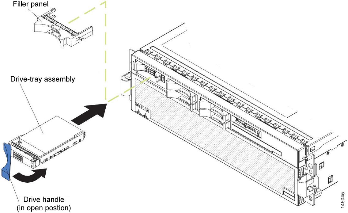
Replacing Hard Disk Drives
Complete the following steps to replace a hard disk drive:
Step 1
Step 2
Step 3
Step 4
Step 5
Figure 3-5 Installing a Hard Disk Drive
 Feedback