Cisco 2-Channel SFP-Based Wavelength Converter Installation Note
Available Languages
Table Of Contents
Cisco 2-Channel SFP-Based Wavelength Converter Installation Note
Statement 1071—Warning Definition
Installing the 2-Channel SFP-Based Wavelength Converter
Installing the 2-Slot Chassis (CWDM-CHASSIS-2=)
Installing the 2-Channel SFP-Based Wavelength Converter
Installing the SFP Transceivers
Cabling the 2-Channel SFP-Based Wavelength Converter
Statement 1008—Class 1 Laser Product
Statement 1030—Equipment Installation
Statement 1040—Product Disposal
Statement 1051—Laser Radiation
Statement 1057—Hazardous Radiation Exposure
Obtaining Documentation and Submitting a Service Request
Cisco 2-Channel SFP-Based Wavelength Converter Installation Note
Revised: January 19, 2012Product Number: WDM-SFP-2CH-CONV=
This document provides installation instructions for the Cisco 2-Channel SFP-Based Wavelength Converter.
Contents
This installation note contains the following sections:
•
Installing the 2-Channel SFP-Based Wavelength Converter
•
•
•
Overview
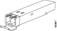
The Cisco 2-Channel SFP-Based Wavelength Converter is a stand-alone dual-channel CWDM converter device. (See Figure 1.) The Cisco 2-Channel SFP-Based Wavelength Converter can accommodate protocols at any data rate between 125 Mbs and 2.67 Mbs. Any combination of SFP transceivers can be used in the converter.
Figure 1 2-Channel SFP-Based Wavelength Converter
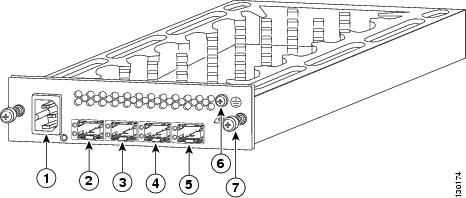
AC-in receptacle
Network2 (NTWK2) SFP socket
Equipment 1 (EQPT1) SFP socket
Chassis ground screw
Network 1 (NWK1) SFP socket
Captive installation screw
Equipment 2 (EQPT2) SFP socket
LEDs
The 2-Channel SFP-Based Wavelength Converter is equipped with LEDs to provide you with the operational status of the unit. Table 1 lists the LEDs and their meanings.
Safety Overview
Throughout this publication, safety warnings appear in procedures that, if performed incorrectly, can harm you. A warning symbol precedes each warning statement.
Statement 1071—Warning Definition
Warning
Warning
Warning
WarningInstalling the 2-Channel SFP-Based Wavelength Converter
The following sections provide installation procedures for the 2-Channel SFP-Based Wavelength Converter:
•
•
Required Tools
You will need these tools to install the 2-Channel SFP-Based Wavelength Converter:
•
•
•
•
http://www.cisco.com/en/US/tech/tk482/tk607/technologies_white_paper09186a0080254eba.shtml
•
•
Installing the 2-Slot Chassis (CWDM-CHASSIS-2=)

Note

Caution
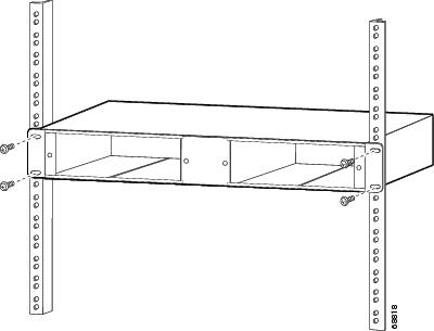
To mount the 2-slot chassis in an equipment rack, follow these steps:
Step 1
Step 2
Step 3
Figure 2 Mounting the 2-Slot Chassis in the Rack
Installing the 2-Channel SFP-Based Wavelength Converter
Caution
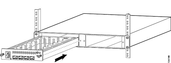
To install the 2-Channel SFP-Based Wavelength Converter in the 2-slot chassis, follow these steps:
Step 1
Step 2
Figure 3 Installing a 2-Channel SFP-Based Wavelength Converter
Step 3
Step 4
Step 5
Step 6
Figure 4 AC In and Chassis Ground Connections
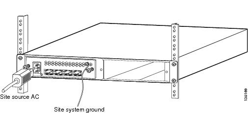
Step 7
Installing the SFP Transceivers
Caution
Removing and installing an SFP transceiver can shorten its useful life. Do not remove and insert SFP transceivers more often than is absolutely necessary.
Caution
SFP transceiver modules can have three types of latching devices to secure an SFP transceiver in a port socket:
•
•
•
Determine which type of latch your SFP transceiver uses before following the installation and removal procedures.
Figure 5 SFP Transceiver Module with a Mylar Tab Latch
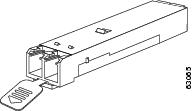
Figure 6 SFP Transceiver Module with an Actuator Button Latch
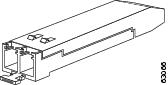
Figure 7 SFP Module with a Bale-Clasp Latch
To install an SFP transceiver, follow these steps:
Step 1
Step 2
Note
Step 3
Step 4
Note
Step 5
Step 6
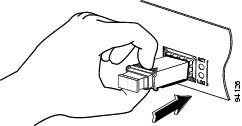
Figure 8 Inserting an SFP Transceiver into a Module Socket
Cabling the 2-Channel SFP-Based Wavelength Converter
Warning
Note
•
•
•
To cable the converter, follow these steps:
Step 1
Step 2

Tip
http://www.cisco.com/en/US/tech/tk482/tk607/technologies_white_paper09186a0080254eba.shtml
Step 3
Step 4
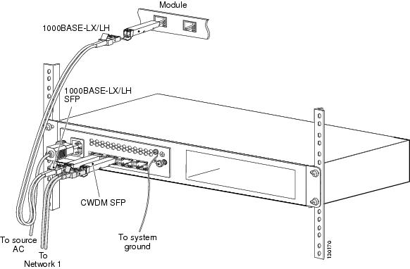
Figure 9 shows a sample cabling scheme for the 2-channel wavelength converter. In this example, you would use 1000BASE-LX/LH SFPs to interface between the module and the 2-channel wavelength converter, and you would use CWDM SFPs to interface from the 2-channel wavelength converter to the network.
Figure 9 Cabling the 2-Channel Wavelength Converter
Regulatory Compliance
This section includes all regulatory, safety, EMC (Class A or Class B), telecom, and NEBS standards. The 2-Channel SFP-Based Wavelength Converter is in compliance with the national and international standards that are listed in Table 2.
Table 2 Regulatory Standards Compliance
Regulatory Compliance
Products bearing the CE mark indicate compliance with the 73/23/EEC and 89/336/EEC directives, which include the safety and EMC standards in this table.
Safety
UL 60950-1
CAN/CSA-C22.2 No. 60950-1
EN 60950-1
IEC 60950-1
TS 001:1997
AS/NZS 60950
21CFR1040
ENG-60825-1
IEC 60825-1
EMC
FCC Part 15 (CFR 47) Class A
ICES-003 Class A
EN 55022 Class A
CISPR 22 Class A
CISPR 24
AS/NZS 3548 Class A
VCCI Class A
EN 55024
EN 300 386
EN 50082-1
EN61000-6-1
Translated Safety Warnings
This section contains the translations to the warnings that appear in this publication.
Statement 1008—Class 1 Laser Product
WarningClass 1 laser product.
Waarschuwing
Klasse-1 laser produkt.
Varoitus
Luokan 1 lasertuote.
Attention
Produit laser de classe 1.
Warnung
Laserprodukt der Klasse 1.
Avvertenza
Prodotto laser di Classe 1.
Advarsel
Laserprodukt av klasse 1.
Aviso
Produto laser de classe 1.
¡Advertencia!
Producto láser Clase I.
Varning!
Laserprodukt av klass 1.


Aviso
Produto a laser de classe 1.
Advarsel
Klasse 1 laserprodukt.


Statement 1030—Equipment Installation
WarningOnly trained and qualified personnel should be allowed to install, replace, or service this equipment.
Waarschuwing
Deze apparatuur mag alleen worden geïnstalleerd, vervangen of hersteld door bevoegd geschoold personeel.
Varoitus
Tämän laitteen saa asentaa, vaihtaa tai huoltaa ainoastaan koulutettu ja laitteen tunteva henkilökunta.
Attention
Il est vivement recommandé de confier l'installation, le remplacement et la maintenance de ces équipements à des personnels qualifiés et expérimentés.
Warnung
Das Installieren, Ersetzen oder Bedienen dieser Ausrüstung sollte nur geschultem, qualifiziertem Personal gestattet werden.
Avvertenza
Questo apparato può essere installato, sostituito o mantenuto unicamente da un personale competente.
Advarsel
Bare opplært og kvalifisert personell skal foreta installasjoner, utskiftninger eller service på dette utstyret.
Aviso
Apenas pessoal treinado e qualificado deve ser autorizado a instalar, substituir ou fazer a revisão deste equipamento.
¡Advertencia!
Solamente el personal calificado debe instalar, reemplazar o utilizar este equipo.
Varning!
Endast utbildad och kvalificerad personal bör få tillåtelse att installera, byta ut eller reparera denna utrustning.


Aviso
Somente uma equipe treinada e qualificada tem permissão para instalar, substituir ou dar manutenção a este equipamento.
Advarsel
Kun uddannede personer må installere, udskifte komponenter i eller servicere dette udstyr.


Statement 1040—Product Disposal
WarningUltimate disposal of this product should be handled according to all national laws and regulations.
Waarschuwing
Het uiteindelijke wegruimen van dit product dient te geschieden in overeenstemming met alle nationale wetten en reglementen.
Varoitus
Tämä tuote on hävitettävä kansallisten lakien ja määräysten mukaisesti.
Attention
La mise au rebut ou le recyclage de ce produit sont généralement soumis à des lois et/ou directives de respect de l'environnement. Renseignez-vous auprès de l'organisme compétent.
Warnung
Die Entsorgung dieses Produkts sollte gemäß allen Bestimmungen und Gesetzen des Landes erfolgen.
Avvertenza
Lo smaltimento di questo prodotto deve essere eseguito secondo le leggi e regolazioni locali.
Advarsel
Endelig kassering av dette produktet skal være i henhold til alle relevante nasjonale lover og bestemmelser.
Aviso
Deitar fora este produto em conformidade com todas as leis e regulamentos nacionais.
¡Advertencia!
Al deshacerse por completo de este producto debe seguir todas las leyes y reglamentos nacionales.
Varning!
Vid deponering hanteras produkten enligt gällande lagar och bestämmelser.


Aviso
O descarte definitivo deste produto deve estar de acordo com todas as leis e regulamentações nacionais.
Advarsel
Endelig bortskaffelse af dette produkt skal ske i henhold til gældende love og regler.


Statement 1051—Laser Radiation
WarningInvisible laser radiation may be emitted from disconnected fibers or connectors. Do not stare into beams or view directly with optical instruments.
Waarschuwing
Losgekoppelde of losgeraakte glasvezels of aansluitingen kunnen onzichtbare laserstraling produceren. Kijk niet rechtstreeks in de straling en gebruik geen optische instrumenten rond deze glasvezels of aansluitingen.
Varoitus
Irrotetuista kuiduista tai liittimistä voi tulla näkymätöntä lasersäteilyä. Älä tuijota säteitä tai katso niitä suoraan optisilla välineillä.
Attention
Les fibres ou connecteurs débranchés risquent d'émettre des rayonnements laser invisibles à l'œil. Ne regardez jamais directement les faisceaux laser à l'œil nu, ni d'ailleurs avec des instruments optiques.
Warnung
Unterbrochene Fasern oder Steckerverbindungenkönnen unsichtbare Laserstrahlung abgeben. Blicken Sie weder mit bloßem Auge noch mit optischen Instrumenten direkt in Laserstrahlen.
Avvertenza
Le fibre ottiche ed i relativi connettori possono emettere radiazioni laser. I fasci di luce non devono mai essere osservati direttamente o attraverso strumenti ottici.
Advarsel
Det kan forekomme usynlig laserstråling fra fiber eller kontakter som er frakoblet. Stirr ikke direkte inn i strålene eller se på dem direkte gjennom et optisk instrument.
Aviso
Radiação laser invisível pode ser emitida de conectores ou fibras desconectadas. Não olhe diretamente para os feixes ou com instrumentos ópticos.
¡Advertencia!
Es posible que las fibras desconectadas emitan radiación láser invisible. No fije la vista en los rayos ni examine éstos con instrumentos ópticos.
Varning!
Osynlig laserstrålning kan avges från frånkopplade fibrer eller kontaktdon. Rikta inte blicken in i strålar och titta aldrig direkt på dem med hjälp av optiska instrument.


Aviso
Radiação laser invisível pode ser emitida a partir de fibras ou conectores desconectados. Não fixe o olhar nos feixes e nem olhe diretamente com instrumentos ópticos.
Advarsel
Usynlig laserstråling kan forekomme fra brugte fibre eller stik. Stir ikke ind i stråler eller direkte med optiske instrumenter.


Statement 1057—Hazardous Radiation Exposure
WarningUse of controls, adjustments, or performing procedures other than those specified may result in hazardous radiation exposure.
Waarschuwing
Het gebruik van regelaars of bijstellingen of het uitvoeren van procedures anders dan opgegeven kan leiden tot blootstelling aan gevaarlijke straling.
Varoitus
Säätimien tai säätöjen käyttö ja toimenpiteiden suorittaminen ohjeista poikkeavalla tavalla voi altistaa vaaralliselle säteilylle.
Attention
L'utilisation de commandes, de réglages ou de procédures autres que ceux spécifiés peut entraîner une exposition dangereuse à des radiations.
Warnung
Die Verwendung von nicht spezifizierten Steuerelementen, Einstellungen oder Verfahrensweisen kann eine gefährliche Strahlenexposition zur Folge haben.
Avvertenza
L'adozione di controlli, regolazioni o procedure diverse da quelle specificate può comportare il pericolo di esposizione a radiazioni.
Advarsel
Bruk av kontroller eller justeringer eller utførelse av prosedyrer som ikke er spesifiserte, kan resultere i farlig strålingseksponering.
Aviso
O uso de controles, ajustes ou desempenho de procedimentos diferentes dos especificados pode resultar em exposição prejudicial de radiação.
¡Advertencia!
La aplicación de controles, ajustes y procedimientos distintos a los especificados puede comportar una exposición peligrosa a la radiación.
Varning!
Om andra kontroller eller justeringar än de angivna används, eller om andra processer än de angivna genomförs, kan skadlig strålning avges.


Aviso
O uso de controles, ajustes ou procedimentos diferentes daqueles especificados pode resultar em exposição perigosa à radiação.
Advarsel
Brug af kontrolfunktioner, justeringer, eller udførelse af procedurer andre end de, der er angivet, kan resultere i udsættelse for farlig bestråling.


Obtaining Documentation and Submitting a Service Request
For information on obtaining documentation, submitting a service request, and gathering additional information, see the monthly What's New in Cisco Product Documentation, which also lists all new and revised Cisco technical documentation, at:
http://www.cisco.com/en/US/docs/general/whatsnew/whatsnew.html
Subscribe to the What's New in Cisco Product Documentation as an RSS feed and set content to be delivered directly to your desktop using a reader application. The RSS feeds are a free service. Cisco currently supports RSS Version 2.0.
This document is to be used in conjunction with the documents shipped with your chassis.
Cisco and the Cisco logo are trademarks or registered trademarks of Cisco and/or its affiliates in the U.S. and other countries. To view a list of Cisco trademarks, go to this URL: www.cisco.com/go/trademarks. Third-party trademarks mentioned are the property of their respective owners. The use of the word partner does not imply a partnership relationship between Cisco and any other company. (1110R)
Copyright © 2005-2012 Cisco Systems, Inc. All rights reserved.


 Feedback
Contact Cisco
- Open a Support Case

- (Requires a Cisco Service Contract)