
Configuring Infra for Cisco NDFC Sites
Prerequisites and Guidelines
The following sections describe the steps necessary to configure the general as well as site-specific fabric Infra settings.
Before you proceed with Infra configuration, you must have added the sites as described in previous sections.
In addition, keep in mind the following:
-
Adding or removing border gateway switches requires a Nexus Dashboard Orchestrator fabric connectivity information refresh described in the Refreshing Site Connectivity Information as part of the general Infra configuration procedures.
Configuring Infra: General Settings
This section describes how to configure general settings for your NDFC sites that are on board and managed by Cisco Nexus Dashboard Orchestrator.
-
Log in to your Cisco Nexus Dashboard and open the Cisco Nexus Dashboard Orchestrator service.
-
In the left navigation menu, choose Configure > Site to Site Connectivity.
-
In the main pane, choose the Configure button.
-
Choose the left tab, which is for General Settings.
-
Provide Control Plane Configuration.
-
Select the Control Plane Configuration tab.
-
Choose BGP Peering Type.
-
full-mesh-All border gateway switches in each site establishes peer connectivity with remote sites' border gateway switches. -
route-server-The route-server option allows you to specify one or more control-plane nodes to which each site establishes MP-BGP EVPN sessions. The route-server nodes perform a function similar to traditional BGP route-reflectors, but for External Border Gateway Protocol (and not Internal Border Gateway Protocol) sessions. The use of route-server nodes avoids creating MP-BGP EVPN full mesh adjacencies between all the VXLAN EVPN sites that are managed by NDO.
-
-
If you set the BGP Peering Type to
route-server, click +Add Route Server to add one or more route servers.In the Add Route Server window that opens:
-
From the Site drop-down, select the site that you want to connect to the route server.
-
The ASN field will be autopopulated with the site’s ASN.
-
From the Core Router Device drop-down, select the route server to which you want to connect.
-
From the Interface drop-down, select the interface on the core router device.
You can add up to 4 route servers. If you add multiple route servers, every site establishes MP-BGP EVPN adjacencies to every route server.
-
-
Leave the Keepalive Interval (Seconds), Hold Interval (Seconds), Stale Interval (Seconds), Graceful Restart, Maximum AS Limit, and BGP TTL Between Peers fields at default values as they are relevant for Cisco ACI fabrics only.
-
-
Provide the On Premises IPsec Devices information.
If your intersite connectivity between on-premises and cloud sites is using private connection and you will not enable IPsec, you can skip this step. For connectivity over public Internet, IPsec is always enabled and you must provide the information in this step.
When you configure intersite underlay connectivity between on-premises and cloud sites as described in later sections, you must select an on-premises IPN device which establishes connectivity to the cloud CSRs. These IPN devices must first be defined here before they are available in the on-premises site configuration screen.
-
Select the On Premises IPsec Devices tab.
-
Click +Add On-Premises IPsec Device.
-
Choose whether the device is Unmanaged or Managed and provide the device information.
This defines whether the device is directly managed by NDFC:
-
For Unmanaged IPN devices, simply provide the Name and the IP Address of the device.
The IP address that you provide will be used as the tunnel peer address from the cloud CSRs, not the IPN device’s management IP address.
-
For Managed IPN devices, choose the NDFC Site that contains the device and then the Device from that site.
Then choose the Interface on the device that is facing the Internet and provide the Next Hop IP address, which is the IP address of the gateway that is connecting to the Internet.
-
-
Click the check mark icon to save the device information.
-
Repeat this step for any additional IPN devices that you want to add.
-
-
Provide the IPsec Tunnel Subnet Pools information.
There are two kinds of subnet pools that you can provide here:
-
External Subnet Pool-Used for connectivity between cloud site CSRs and other sites (cloud or on-premises).
These are large global subnet pools that are managed by Cisco Nexus Dashboard Orchestrator. The Orchestrator creates smaller subnets from these Pools and allocates them to sites to be used for intersite IPsec tunnels and external connectivity IPsec tunnels.
You must provide at least one external subnet pool if you want to enable external connectivity from one or more of your cloud sites.
-
Site-Specific Subnet Pool-Used for connectivity between cloud site CSRs and external devices.
These subnets can be defined when the external connectivity IPsec tunnels must be in a specific range. For example, where a specific subnet is already being used to allocate IP addresses to the external router and you want to continue using those subnets for IPsec tunnels for NDO and cloud sites. These subnets are not managed by the Orchestrator and each subnet is assigned to a site in its entirety to be used locally for external connectivity IPsec tunnels.
If you do not provide any named subnet pools but still configure connectivity between the cloud site’s CSRs and external devices, the external subnet pool will be used for IP allocation. .

The minimum mask length for both subnet pools is
/24.
To add one or more External Subnet Pools:
-
Select the IPsec Tunnel Subnet Pools tab.
-
In the External Subnet Pool area, click +Add IP Address to add one or more external subnet pools.
This subnet will be used to address the IPsec tunnel interfaces and loopbacks of the Cloud Routers that are used for on-premises connectivity, which you previously configured in the Cloud Network Controller for intersite connectivity in earlier Cisco Nexus Dashboard Orchestrator releases.
The subnets must not overlap with other on-premises TEP Pools, should not begin with
0.x.x.xor0.0.x.x, and should have a network mask between/16and/24, for example30.29.0.0/16. -
Click the check mark icon to save the subnet information.
-
Repeat these substeps for any additional subnet pools that you want to add.
-
To add one or more Site-Specific Subnet Pools:
-
Select the IPsec Tunnel Subnet Pools tab.
-
In the Site-Specific Subnet Pools area, click +Add IP Address to add one or more external subnet pools.
The Add Named Subnet Pool dialogue opens.
-
Provide the subnet Name.
You can use the subnet pool’s name to choose the pool from which to allocate the IP addresses later on.
-
Click +Add IP Address to add one or more subnet pools.
The subnets must have a network mask between
/16and/24and not begin with0.x.x.xor0.0.x.x, for example30.29.0.0/16. -
Click the check mark icon to save the subnet information.
Repeat the steps if you want to add multiple subnets to the same named subnet pool.
-
Click Save to save the named subnet pool.
-
Repeat these substeps for any additional named subnet pools that you want to add.
-
-
Configure NDFC Settings.
-
Select the NDFC Settings tab.
-
Provide the L2 VXLAN VNI Range.
-
Provide the L3 VXLAN VNI Range.
-
Provide the Multi-Site Routing Loopback IP Range.
This field is used to autopopulate the Multi-Site TEP field for each fabric, which is described in Configuring Infra: NDFC Site-Specific Settings.
For sites that were previously part of a Multi-Site Domain (MSD) in NDFC, this field will be prepopulated with the previously defined value.
-
Provide the Anycast Gateway MAC.
-
Refreshing Site Connectivity Information
Infrastructure changes, such as adding and removing border gateway switches, require a Cisco Nexus Dashboard Orchestrator fabric connectivity Refresh. This section describes how to pull up-to-date connectivity information directly from each site’s controller.
-
Log in to the Cisco Nexus Dashboard Orchestrator GUI.
-
In the left navigation menu, select Configure > Site to Site Connectivity.
-
In the top right of the main pane, click Configure.
-
In the left sidebar, under Sites, select a specific site.
-
In the main window, click the Refresh button to pull fabric information from the controller.
-
(Optional) In the Confirmation dialog, check the box if you want to remove the configuration for decommissioned border gateway switches.
If you choose to enable this check box, all configuration info for any currently decommissioned border gateway switches will be removed from the database.
-
Finally, click Yes to confirm and load the connectivity information.
This discovers any new or removed border gateways and all site-related fabric connectivity will be reimported from the site’s controller.
Configuring Infra: NDFC Site-Specific Settings
This section describes how to configure site-specific Infra settings for on-premises sites.
-
Log in to your Cisco Nexus Dashboard and open the Cisco Nexus Dashboard Orchestrator service.
-
In the left navigation menu, choose Configure > Site to Site Connectivity.
-
In the main pane, click Configure.
-
In the left pane, under Sites, choose a specific NDFC.
-
In the right <Site> Settings sidebar, specify the Multi-Site VIP.
This address is used for the intersite L2 BUM and L3 multicast traffic. The IP address is deployed in all border gateway switches that are part of the same fabric.
If the site you are configuring is part of the NDFC Multi-Site Domain (MSD), this field will be prepopulated with the information imported from NDFC. In this case, changing the value and redeploying the configuration, impacts traffic between the sites that are part of the MSD.
You can choose to Auto Allocate this field, which allocates the next available address from the Multi-Site Routing Loopback IP Range you defined in the previous section.
-
Within the <fabric-name> tile, choose the border gateway.
-
In the right <border-gateway> setting sidebar, specify the BGP-EVPN ROUTER-ID and BGW PIP.
For border gateways that are part of a vPC domain, you must also specify a VPC VIP.
You can also choose to deploy a shared border configuration, this configuration allows you to share these services through these devices, while also providing a means to cross the "border" from the internal sites to the Internet. For more information on see, Configuring Shared Border in Cisco Nexus Dashboard Fabric Controller.
-
Click Add Port to configure the port that connects to the IPN.
This release does not support importing the port configuration from the NDFC. If you are configuring a site which is already part of the NDFC Multi-Site Domain (MSD), you must use the same values that are configured in NDFC.
You can use the Inherit BGP Authentication and BFD radio button to inherit settings across, sites and fabrics.
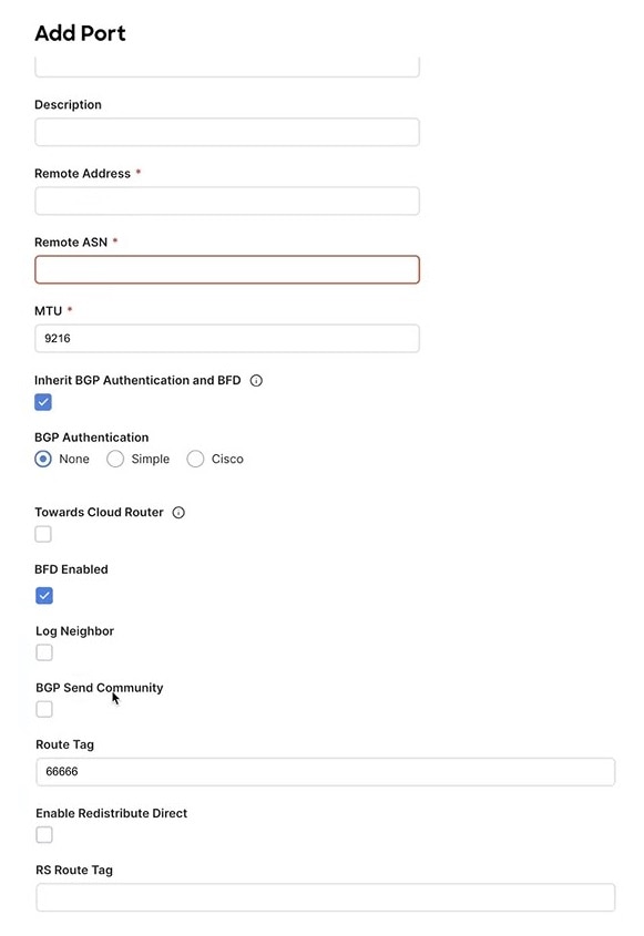 Figure 1. NDFC Settings - Add Port
Provide the following information specific to your deployment for the port that connects this border gateway to a core switch or another border gateway:
-
From the Ethernet Port ID drop-down, choose the port that connects to the IPN.
-
In the IP Address field, enter the IP address and netmask.
-
In the Remote Address field, provide the IP address of the remote device to which the port is connected.
-
In the Remote ASN field, provide the remote site’s Autonomous System Number.
-
In the MTU field, enter the port’s maximum transmission unit.
Maximum transmission unit of the spine port must match MTU on the IPN side.
You can specify either
inheritor value between576and9000. -
For BGP Authentication, you can pick either
NoneorSimple(MD5) orCisco.Provide the Authentication Key if you choose
SimpleorCiscoauthentication methods. -
Check the BFD Enabled, Log Neighbor, and BGP Send Community radio buttons to inherit all these features to all the multisite underlay interfaces.
-
Route Tag is used to configure the data path across all the switches and is propagated to all the nodes in the fabric. Loopback 0, 1 and 100. Select Enable Redistribute Direct if the route tag is specified.
-
Deploying Infra Configuration
You must have the general and site-specific infra configurations completed as described in the previous sections of this chapter.
This section describes how to deploy the Infra configuration to each NDFC site.
-
Ensure that there are no configuration conflicts or resolve them if necessary.
The Deploy button will be disabled and a warning will be displayed if there are any configuration conflicts from the already configured settings in each site. For example, if a VRF or network with the same name exists in multiple sites but uses different VNI in each site.
If configuration conflicts:
-
Click Click to View the link in the conflict notification pop-up.
 Figure 2. Click to View
 -
Note down the specific configurations that are causing the conflicts.
For example, in the following report, there are ID mismatches between VRFs and networks in
fab1andfab2sites.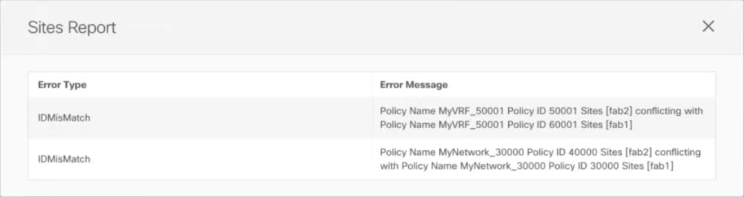 Figure 3. Sites Report
 -
Click the X button to close the report, then exit Infra configuration screen.
-
Unmanage the site in NDO, as described in Removing Sites.
You do not need to remove the site from the Cisco Nexus Dashboard, simply unmanage it in the NDO GUI.
-
Resolve the existing configuration conflicts.
-
Manage the site again, as described in Adding Cisco NDFC Sites.
Since the site is already added in Cisco Nexus Dashboard, simply enable it for management in NDO.
-
Verify that all conflicts are resolved and the Deploy button is available.
-
-
Deploy configuration.
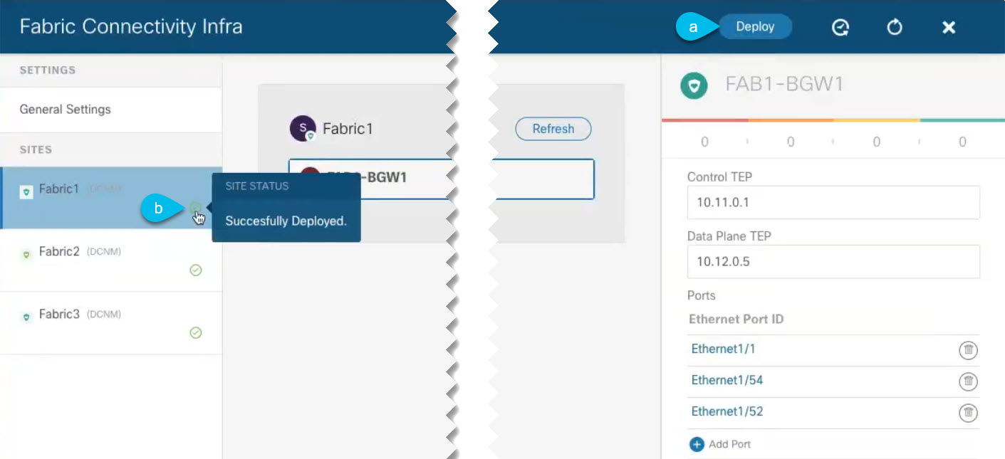 Figure 4. Deploy Configuration
-
In the top right of the Fabric Connectivity Infra screen, choose the appropriate Deploy option to deploy the configuration.
If you are configuring only NDFC sites, simply click Deploy to deploy the Infra configuration.
-
Wait for configuration to be deployed.
When you deploy infra configuration, NDO signals the NDFC to configure the underlay and the EVPN overlay between the border gateways.
When configuration is successfully deployed, you see a green check mark next to the site in the Fabric Connectivity Infra screen:
-
Adding and Deleting Sites
Adding Cisco NDFC Sites
-
You must ensure that the site(s) you are adding are running Cisco NDFC, Release 11.5(1) or later.
This section describes how to add a NDFC site using the Nexus Dashboard GUI and then enable that site to be managed by Nexus Dashboard Orchestrator.
-
Log in to your Nexus Dashboard and open the Admin Console.
-
From the left navigation menu, choose Sites and click Add Site..
-
Provide site information.
-
For Site Type, select NDFC or NDFC.
-
Provide the NDFC controller information.
You need to provide the Host Name/IP Address of the in-band (
eth2) interface, User Name, and Password. for the NDFC controller currently managing your NDFC fabrics. -
Click Select Sites to select the specific fabrics managed by the controller.
In the fabric selection window that opens, select the fabrics you want to add to the Nexus Dashboard and click Select:
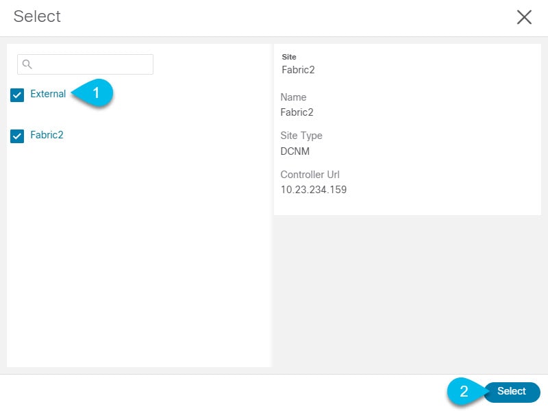 Figure 5.
 -
Click Add Security Domains to select one or more security domains that will have access to this site.
-
-
Repeat the previous steps for any additional NDFC sites.
-
From the Nexus Dashboard’s Service Catalog page, open the Nexus Dashboard Orchestrator service.
You will be automatically logged in using the Nexus Dashboard user’s credentials.
-
In the Nexus Dashboard Orchestrator GUI, manage the sites.
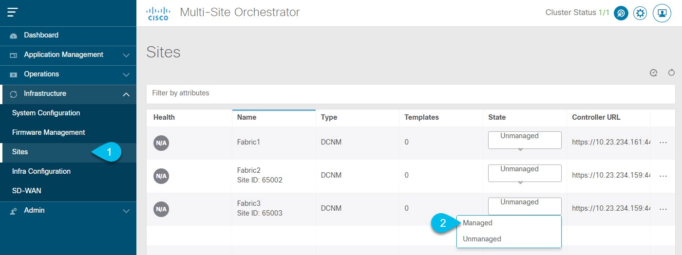 Figure 6.
-
From the left navigation menu, select Infrastructure > Sites.
-
In the main pane, change the State from
UnmanagedtoManagedfor each fabric that you want the NDO to manage.If the fabric you are managing is part of a Multi-Site Domain (MSD), it will have a Site ID already associated with it. In this case, simply changing the State to
Managedwill manage the fabric.However, if the fabric is not part of an MSD, you will also be prompted to provide a Fabric ID for the site when you change its state to
Managed.
If you want to manage both kinds of fabrics, those that are part of an existing MSD and those that are not, you must on-board the MSD fabrics first, followed by any standalone fabrics.
-
Removing Sites
You must ensure that all templates associated with the site you want to remove are not deployed.
This section describes how to disable site management for one or more sites using the Nexus Dashboard Orchestrator GUI. The sites will remain present in the Nexus Dashboard.
-
Open the Nexus Dashboard Orchestrator GUI.
You can open the NDO service from the Nexus Dashboard’s Service Catalog. You will be automatically logged in using the Nexus Dashboard user’s credentials.
-
Remove the site from all templates.
You must remove the site from all templates with which it is associated before you can unmanaged the site and remove it from your Nexus Dashboard.
-
Navigate to Application Management > Schemas.
-
Click a schema that contains one or more templates associated with the site.
-
From the View dropdown, choose a template that’s associated with the site that you want to remove.
-
From the Actions dropdown, choose Sites Association and uncheck the site you want to remove.
This will remove configurations that were deployed using this template to this site.
For non-stretched templates, you can choose to preserve the configurations deployed by the template to the sites by selecting Actions > Dissociate Sites instead. This option will allow you to retain configurations deployed by NDO but no longer manage those objects from NDO.
-
Repeat this step for all templates associated with the site that you want to unmanage in this and all other schemas.
-
-
In the Nexus Dashboard Orchestrator GUI, disable the sites.
-
From the left navigation menu, select Sites.
-
In the main pane, change the State from
ManagedtoUnmanagedfor the site that you want to unmanage.
If the site is associated with one or more deployed templates, you will not be able to change its state to
Unmanageduntil you undeploy those templates, as described in the previous step.
-
-
Delete the site from Nexus Dashboard.
If you no longer want to manage this site or use it with any other applications, you can delete the site from the Nexus Dashboard as well.
Note that the site must not be currently in use by any of the services installed in your Nexus Dashboard cluster.
-
In the top navigation bar, click the Home icon to return to the Nexus Dashboard GUI.
-
From the left navigation menu of the Nexus Dashboard GUI, select Sites.
-
Select one or more sites you want to delete.
-
In the top right of the main pane, select Actions > Delete Site.
-
Provide the site’s login information and click OK.
The site will be removed from the Nexus Dashboard.
-
Cross Launch to Fabric Controllers
Cisco Nexus Dashboard Orchestrator currently supports several configuration options for each type of fabrics. For many extra configuration options, you may need to sign in directly into the fabric’s controller.
You can cross-launch into the specific site controller’s GUI from the NDO’s Operate > Sites screen by selecting the actions (…) menu next to the site and clicking Open in user interface. Cross-launch works with out-of-band (OOB) management IP of the fabric.
If the same user is configured in Cisco Nexus Dashboard and the fabric, you will be signed in automatically into the fabric’s controller using the same log in information as the Cisco Nexus Dashboard user. For consistency, we recommend configuring remote authentication with common users across Cisco Nexus Dashboard and the fabrics. :leveloffset: -1
First Published: 2024-03-11
Last Modified: 2024-03-11
Americas Headquarters
Cisco Systems, Inc.
170 West Tasman Drive
San Jose, CA 95134-1706
USA
http://www.cisco.com
Tel: 408 526-4000
800 553-NETS (6387)
Fax: 408 527-0883