
Overview and Use Cases
Starting with Nexus Dashboard Orchestrator release 3.0(1) and APIC Release 5.0(1), the Multi-Site architecture provides better hand-off functionality between ACI border leaf (BL) switches and SR-MPLS networks.
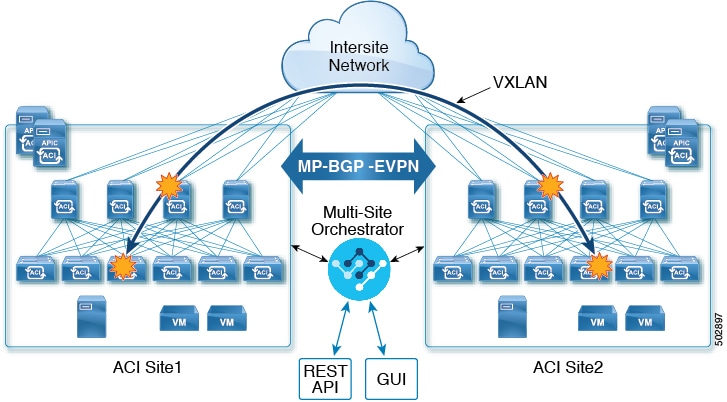
In a typical Multi-Site deployment, traffic between sites is forwarded over an intersite network (ISN) via VXLAN encapsulation:
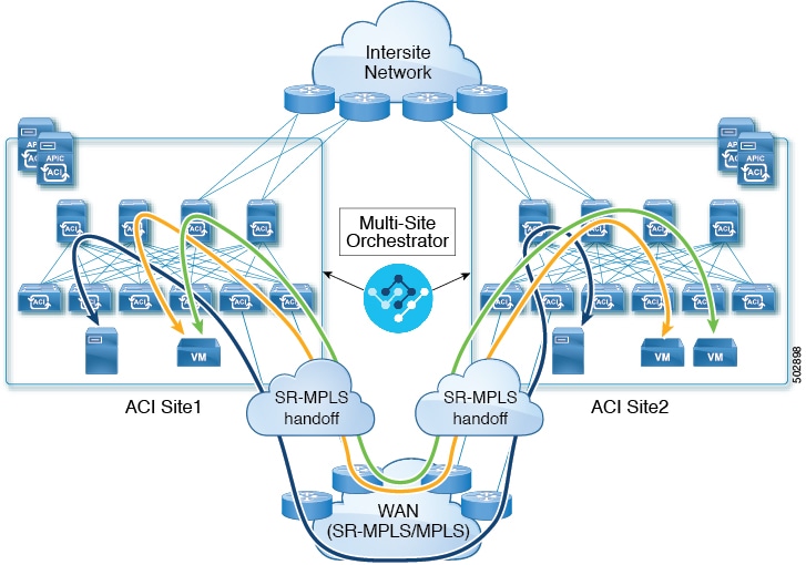
With Release 3.0(1), MPLS network can be used in addition to or instead of the ISN allowing inter-site communication via WAN, as shown in the following figure. In order to force East-West Layer 3 communication to follow the SR-MPLS L3Out data path (instead of the VXLAN data path across the ISN), several restrictions had to be applied to this SR-MPLS hand-off use case:
-
The VRF to which the SR-MPLS L3Out belongs must not be stretched across sites.
-
Because of the above restriction, every site must deploy one (or more) local SR-MPLS L3Outs for each defined site-local VRF.
-
Contracts must not be applied between site-local EPGs belonging to different VRFs.
This forces the communication to follow the SR-MPLS L3Out data path.
Additional Use Cases in NDO Release 4.0(2) and Later
Prior to NDO release 4.0(2), if you wanted to deploy the SR-MPLS use case, you would define a special "SR-MPLS" template that could be associated with only a single site and not stretched across multiple sites. In this case, if you had two sites managed by your Nexus Dashboard Orchestrator and connected via an SR-MPLS network, and you wanted to establish communication between an EPG in site1 and another EPG in site2, you had to deploy two separate SR-MPLS-VRF-L3Outs (one in each site) associated with two separate VRFs and establish contracts between the EPG in each site and that site’s SR-MPLS L3Out (instead of directly between the EPGs). In other words, the EPGs' traffic would always use the SR-MPLS data path even for EPG-to-EPG communication across sites without integrating with the traditional Multi-Site data plane for East-West traffic.
Beginning with release 4.0(2), the SR-MPLS L3Outs can function similar to the traditional IP-based L3Outs which allows you to use the SR-MPLS L3Out hand-offs exclusively for North-South connectivity between a site and an external network, while all East-West traffic can be handled in the traditional Multi-Site manner using VXLAN-encapsulated data plane across the ISN. This means that the SR-MPLS hand-offs can now be treated as traditional IP-based hand-offs and the same VRF can deploy a mix of IP and SR-MPLS L3Outs. These changes add support for the following specific use cases:
-
Deployment of multiple sites each with their own local SR-MPLS-VRF-L3Outs and intra-VRF traffic using the local L3Out if it is available or a remote SR-MPLS-VRF-L3Out from another site (intersite L3Out).
In this case, the remote SR-MPLS-VRF-L3Out can be used as a simple backup or to reach unique external prefixes received on the remote SR-MPLS-VRF-L3Out. Traffic will transit from a local EPG to the local SR-MPLS-VRF-L3Out and if that path is down or the route is unavailable it can take another site’s remote SR-MPLS-VRF-L3Out.
-
Similar use cases are supported for shared services, where application EPG in one VRF can use SR-MPLS-VRF-L3Out in a different VRF, either in the local or remote site.
In this case, the EPGs can be in a different tenant as well. For example, Tenant1 in Site1 can contain the application EPGs which will use an SR-MPLS-VRF-L3Out in Tenant2 in Site2.
-
Ability to combine IP-based and SR-MPLS hand-offs.
Using SR-MPLS L3Outs (instead of traditional IP-based L3Outs) allows for operational simplification at higher scale by removing the need for the VRF-Lite configuration which requires creation of separate BL nodes, BL logical interfaces, and routing peering for each VRF that needs to be connected to the external network. With the SR-MPLS L3Outs, the logical nodes and logical interfaces are defined once in the infra tenant, together with a single MP-BGP EVPN peering with the external devices. This infra L3Out construct can then be used to provide external connectivity to multiple tenant VRFs and all the VRFs' prefixes are exchanged using the common MP-BGP EVPN control plane.
The following sections describe guidelines, limitations, and configurations specific to managing Schemas that are deployed to sites from the Nexus Dashboard Orchestrator. Detailed information about MPLS hand off, supported individual site topologies (such as remote leaf support), and policy model is available in the Cisco APIC Layer 3 Networking Configuration Guide.
Configuration Workflow
Other sections in this document detail the required configurations, but in short you will go through the following workflow:
-
Create an SR-MPLS QoS policy.
SR-MPLS Custom QoS policy defines the priority of the packets coming from an SR-MPLS network while they are inside the ACI fabric based on the incoming MPLS EXP values defined in the MPLS QoS ingress policy. It also marks the CoS and MPLS EXP values of the packets leaving the ACI fabric through an MPLS interface based on IPv4 DSCP values defined in MPLS QoS egress policy.
This is an optional step and if no custom ingress policy is defined, the default QoS Level (
Level3) is assigned to packets inside the fabric. If no custom egress policy is defined, the default EXP value of0will be marked on packets leaving the fabric. -
Create an SR-MPLS Infra L3Out.
This configures an L3Out for traffic leaving a site that is connected to an SR-MPLS network.
The same SR-MPLS Infra L3Out can then be used by multiple SR-MPLS Tenant L3Outs for control and data plane communication with the external network domain.
-
Create SR-MPLS route map policy that matches specific Tenant’s prefixes.
Route maps are sets of
if-thenrules that enable you to specify which routes are advertised out of the Tenant SR-MPLS L3Out. Route maps also enable you to specify which routes received from the DC-PE routers will be injected into the BGP VPNv4 ACI control plane. -
If you want to deploy a use case similar to releases prior to release 4.0(2), create the VRF, SR-MPLS L3Out, and SR-External EPG for each site connected via an SR-MPLS network and establish a contract within each site between that site’s tenant EPG and SR-External EPG.
In this case, all communication from one site will follow the North-South route egressing your Multi-Site domain towards the external SR-MPLS network. If the traffic is destined to an EPG in another site managed by your Orchestrator, it will ingress the other fabric from the external network using that site’s SR-MPLS L3Out.
-
If you want to use the SR-MPLS L3Outs in the same way as the standard IP-based L3Out exclusively for North-South communication, you can create the VRFs, SR-MPLS L3Outs, EPGs, and contracts as you typically would for all existing EPG-to-EPG communication use cases.
SR-MPLS Infra Requirements and Guidelines
If you want to use your Nexus Dashboard Orchestrator to manage SR-MPLS L3Out hand-offs for an ACI fabric connected to an SR-MPLS network:
-
Any changes to the topology, such as node updates, are not reflected in the Orchestrator configuration until site configuration is refreshed, as described in Refreshing Site Connectivity Information.
-
Any Multi-Site traffic across different sites cannot ingress or egress through Remote Leaf switches.
This limitation is not specific to SR-MPLS use cases and applies to all Multi-Site traffic in general.
-
SR-External EPGs that are part of preferred group cannot be the providers of a shared service (inter-VRF) contract.
-
Preferred Group is not supported for Intersite SR-MPLS L3Outs.
-
vzAny is not supported as a shared service provider.
-
VRF that is enabled for Preferred Group cannot be a vzAny consumer.
-
We recommend configuring tenant contract objects under dedicated template to avoid circular dependencies with other configuration objects that use the same contracts
-
When using SR-MPLS L3Out instead of traditional IP-based L3Outs:
-
Host-based routing advertisement is not supported for bridge domains that are stretched across sites.
-
Tenant Routed Multicast (TRM) is not supported with SR-MPLS L3Outs, so they can only be used for establishing Layer 3 unicast communication with the external network domain.
-
Supported Hardware
The SR-MPLS hand-off is supported for the following platforms:
-
Border Leaf switches: The "FX", "FX2", "GX", and "GX2" switch models.
-
Spine switches:
-
Modular spine switch models with "LC-EX", "LC-FX", and "GX" at the end of the linecard names.
-
The Cisco Nexus 9000 series N9K-C9332C, N9K-C9364C, "-GX", and "-GX2" fixed spine switches.
-
-
DC-PE routers:
-
Network Convergence System (NCS) 5500 Series
-
ASR 9000 Series
-
NCS 540 or 560 routers
-
SR-MPLS Infra L3Out
You will need to create an SR-MPLS Infra L3Out for the fabrics connected to SR-MPLS networks as described in the following sections. When creating an SR-MPLS Infra L3Out, the following restrictions apply:
-
Each SR-MPLS Infra L3Out must have a unique name.
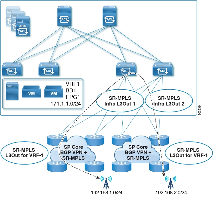
The SR-MPLS Infra L3Out allows you to establish the control plane and data plane connectivity between the ACI border leaf switches and the external Provider Edge (PE) devices. SR-MPLS L3Outs that belong to various tenant VRFs can then leverage that Infra L3Out connectivity to establish communication with the external network domain.
-
You can have multiple SR-MPLS infra L3Outs connecting to different routing domains, where the same border leaf switch can be in more than one L3Out, and you can have different import and export routing policies for the VRFs toward each routing domain.
-
Even though a border leaf switch can be in multiple SR-MPLS infra L3Outs, a border leaf switch/provider edge router combination can only be in one SR-MPLS infra L3Out as there can be only one routing policy for a user VRF/border leaf switch/DC-PE combination.
-
If there is a requirement to have SR-MPLS connectivity from multiple pods and remote locations, ensure that you have a different SR-MPLS infra L3Out in each of those pods and remote leaf locations with SR-MPLS connectivity.
-
If you have a Multi-Pod or Remote Leaf topology where one of the pods is not connected directly to the SR-MPLS network, that pod’s traffic destined for the SR-MPLS network will use standard IPN path to another pod, which has an SR-MPLS L3Out. Then the traffic will use the other pod’s SR-MPLS L3Out to reach its destination across SR-MPLS network.
This also can apply to Multi-Site deployments where North-South communication for the endpoints in
Site 1can be established via an SR-MPLS L3Out connection inSite 2. -
Routes from multiple VRFs can be advertised from one SR-MPLS Infra L3Out to provider edge (PE) routers connected to the nodes in this SR-MPLS Infra L3Out.
PE routers can be connected to the border leaf directly or through other provider (P) routers.
-
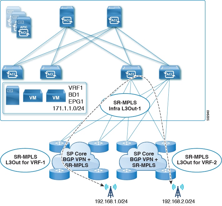
The underlay configuration can be different or can be the same across multiple SR-MPLS Infra L3Outs for one location.
For example, assume the same border leaf switch connects to PE-1 in domain 1 and PE-2 in domain 2, with the underlay connected to another provider router for both. In this case, two SR-MPLS Infra L3Outs will be created: one for PE-1 and one for PE-2. But for the underlay, it’s the same BGP peer to the provider router. Import/export route-maps will be set for EVPN session to PE-1 and PE-2 based on the corresponding route profile configuration in the user VRF.
MPLS Custom QoS Policies
Following is the default MPLS QoS behavior:
-
All incoming MPLS traffic on the border leaf switch is classified into QoS Level 3 (the default QoS level).
-
The border leaf switch will retain the original DSCP values for traffic coming from SR-MPLS without any remarking.
-
The border leaf switch will forward packets with the default MPLS EXP (0) to the SR-MPLS network.
Following are the guidelines and limitations for configuring MPLS Custom QoS policies:
-
Data Plane Policers (DPP) are not supported at the SR-MPLS L3Out.
-
Layer 2 DPP works in the ingress direction on the MPLS interface.
-
Layer 2 DPP works in the egress direction on the MPLS interface in the absence of an egress custom MPLS QoS policy.
-
VRF level policing is not supported.
SR-MPLS Tenant Requirements and Guidelines
While the Infra MPLS configuration and requirements are described in the Day-0 operations chapter, the following restrictions apply for any user Tenants you will deploy to sites that are connected to SR-MPLS networks.
-
In case when traffic between two EPGs in the fabric needs to go through the SR-MPLS network:
-
Contracts must be assigned between each EPG and the SR-External EPG defined on the local Tenant SR-MPLS L3Out.
-
If both EPGs are part of the same ACI fabric but separated by an SR-MPLS network (for example, in Multi-Pod or remote leaf cases), the EPGs must belong to different VRFs and not have a contract between them nor route-leaking configured.
-
If EPGs are in different sites, they can be in the same VRF, but there must not be a contract configured directly between the EPGs and any other remote EPG that is part of the same VRF.
-
-
When configuring a route map policy for the SR-MPLS L3Out:
-
Each L3Out must have a single export route map. Optionally, it can also have a single import route map.
-
Routing maps associated with any SR-MPLS L3Out must explicitly define all the routes, including bridge domain subnets, which must be advertised out of the SR-MPLS L3Out.
-
If you configure a
0.0.0.0/0prefix and choose to not aggregate the routes, it will allow the default route only.However, if you choose to aggregate routes for the
0.0.0.0/0prefix, it will allow all routes. -
You can associate any routing policy with any tenant L3Out.
-
-
Beginning with Nexus Dashboard release 4.0(1), transit routing between SR-MPLS networks is supported using the same or different VRFs for fabrics running Cisco APIC release 5.1(1) or later.
Prior releases supported transit routing using different VRFs only.
Greenfield Deployment
Creating Custom QoS Policy for SR-MPLS
SR-MPLS Custom QoS policy defines the priority of the packets coming from an SR-MPLS network while they are inside the ACI fabric based on the incoming MPLS EXP values defined in the MPLS QoS ingress policy. It also marks the CoS and MPLS EXP values of the packets leaving the ACI fabric through an MPLS interface based on IPv4 DSCP values defined in MPLS QoS egress policy.

Creating custom QoS policy is optional. If no custom ingress policy is defined, the default QoS Level (Level3) is assigned to packets inside the fabric. If no custom egress policy is defined, the default EXP value of 0 will be marked on packets leaving the fabric.
-
Log in to your Cisco Nexus Dashboard and open the Cisco Nexus Dashboard Orchestrator service.
-
Create a new Fabric Policy.
-
From the left navigation pane, choose Configure > Fabric Template > Fabric Policies.
-
On the Fabric Policy Templates page, click Create Fabric Policy Template.
-
From the +Create Object drop-down, select QoS SR-MPLS.
-
In the right properties sidebar, provide the Name for the policy.
-
(Optional) Click Add Description and provide a description for the policy.
-
-
Click Add Ingress Rule to add an ingress QoS translation rule.
These rules are applied for traffic that is ingressing the ACI fabric from an MPLS network and are used to map incoming packet’s experimental bits (EXP) values to ACI QoS levels, and set DSCP or CoS values that the packet should have set when forwarded to an endpoint connected to the fabric.
The values are derived at the border leaf switch using a custom QoS translation policy. If a custom policy is not defined or not matched, default QoS Level (
Level3) is assigned.-
In the Match EXP From and Match EXP To fields, specify the EXP range of the ingressing MPLS packet you want to match.
-
From the Queuing Priority drop-down, select the ACI QoS Level to map.
This is the QoS Level that you want to assign for the traffic within ACI fabric, which ACI uses to prioritize the traffic within the fabric. The options range from Level 1 to Level 6. The default value is
Level3. If you do not make a selection in this field, the traffic will automatically be assigned aLevel3priority. -
From the Set DSCP drop-down, select the DSCP value to be used when sending the unencapsulated packet to an endpoint connected to the fabric.
The DSCP value that is specified is set in the original traffic that is received from the external network, so it will be reexposed only when the traffic is VXLAN decapsulated on the destination ACI leaf node.
If you set the value to
Unspecified, the original DSCP value of the packet will be retained. -
From the Set CoS drop-down, select the CoS value to be used when sending the unencapsulated packet to an endpoint connected to the fabric.
The CoS value that is specified will be reexposed only when the traffic is VXLAN decapsulated on the destination ACI leaf node.
If you set the value to
Unspecified, the original CoS value of the packet will be retained.In both of the above cases, the CoS preservation option must be enabled in the fabric. For more information about CoS preservation, see Cisco APIC and QoS.
-
Click the check mark icon to save the rule.
-
Repeat this step for any additional ingress QoS policy rules.
-
-
Click Add Egress Rule to add an egress QoS translation rule.
These rules are applied for the traffic that is leaving the ACI fabric through an MPLS L3Out and are used to map the packet’s IPv4 DSCP value to the MPLS packet’s EXP value and the internal Ethernet frame’s CoS value.
The setting of the packet’s IPv4 DSCP value is done at the nonborder leaf switch based on existing policies that are used for EPG and L3Out traffic. If a custom policy is not defined or not matched, the default EXP value of
0is marked on all labels. EXP values are marked in both, default and custom policy scenarios, and are done on all MPLS labels in the packet.Custom MPLS egress policy can override existing EPG, L3Out, and Contract QoS policies.
-
Using the Match DSCP From and Match DSCP To dropdowns, specify the DSCP range of the ACI fabric packet you want to match for assigning the egressing MPLS packet’s priority.
-
From the Set MPLS EXP drop-down, select the EXP value that you want to assign to the egressing MPLS packet.
-
From the Set CoS drop-down, select the CoS value that you want to assign to the egressing MPLS packet.
-
Click the check mark icon to save the rule.
-
Repeat this step for any additional egress QoS policy rules.
-
-
From the Actions menu, select Add/Remove Sites and choose the SR-MPLS site with which to associate this template.
-
Click Save to save the template policy.
-
Click Deploy to deploy the fabric policy to the sites.
After you have created the QoS policy, enable MPLS connectivity and configure MPLS L3Out as described in Creating SR-MPLS Infra L3Out.
Creating SR-MPLS Infra L3Out
You must have:
-
Added a site that is connected through SR-MPLS network as described in Adding Cisco ACI Sites.
-
If necessary, created SR-MPLS QoS policy as described in Creating Custom QoS Policy for SR-MPLS.
This section describes how to configure SR-MPLS Infra L3Out settings for a site that is connected to an SR-MPLS network.
-
The SR-MPLS infra L3Out is configured on the border leaf switch, which is used to set up the underlay BGP-LU and overlay MP-BGP EVPN sessions that are needed for the SR-MPLS hand-off.
-
An SR-MPLS infra L3Out will be scoped to a pod or a remote leaf switch site.
-
Border leaf switches or remote leaf switches in one SR-MPLS infra L3Out can connect to one or more provider edge (PE) routers in one or more routing domains.
-
A pod or remote leaf switch site can have one or more SR-MPLS infra L3Outs.
-
Ensure that SR-MPLS Connectivity is enabled for the site.
-
In the main navigation menu, select Configure > Site To Site Connectivity.
-
In the Site To Site Connectivity page, click Configure.
-
In the left pane, under Sites, select the specific site that is connected through SR-MPLS.
-
In the right <Site> Settings pane, enable the SR-MPLS Connectivity and provide the SR-MPLS information.
-
The Segment Routing Global Block (SRGB) Range is the range of label values that are reserved for Segment Routing (SR) in the Label Switching Database (LSD). The Segment ID (SID) is a unique identifier for a specific segment and is configured on each node for the MPLS transport loopback. The SID index, which you configure later as part of the border leaf switch configuration, is advertised using BGP-LU to the peer router, and the peer router uses the SID index to calculate the local label.
The default range is
16000-23999. -
The Domain ID Base enables the BGP Domain-Path feature. For more information, see Cisco APIC Layer 3 Networking Configuration Guide.
If you choose to provide a value in this field to enable the Domain-Path feature, ensure that you use a unique value for each SR-MPLS site in your Multi-Site domain, which will be specific to this ACI fabric.
-
-
-
In the main pane, click +Add SR-MPLS L3Out within a pod.
-
In the right Properties pane, provide a name for the SR-MPLS L3Out.
-
(Optional) From the QoS Policy drop-down, select a QoS Policy that you created for SR-MPLS traffic.
Select the QoS policy that you created in Creating Custom QoS Policy for SR-MPLS.
Otherwise, if you do not assign a custom QoS policy, the following default values are assigned:
-
All incoming MPLS traffic on the border leaf switch is classified into QoS Level 3 (the default QoS level).
-
The border leaf switch does the following:
-
Retains the original DSCP values for traffic coming from SR-MPLS without any remarking.
-
Forwards packets to the MPLS network with the original CoS value of the tenant traffic if the CoS preservation is enabled.
-
Forwards packets with the default MPLS EXP value (
0) to the SR-MPLS network.
-
-
In addition, the border leaf switch does not change the original DSCP values of the tenant traffic coming from the application server while forwarding to the SR network.
-
-
From the L3 Domain drop-down, select the Layer 3 domain.
-
Configure settings for border leaf switches and ports that are connected to the SR-MPLS network.
You must provide information about the border leaf switches and the interface ports which connect to the SR-MPLS network.
-
Click +Add Leaf to add a leaf switch.
-
In the Add Leaf window, select the leaf switch from the Leaf Name drop-down.
-
In the SID Index field, provide a valid segment ID (SID) offset.
When configuring the interface ports later in this section, you are able to choose whether you want to enable segment routing. The SID index is configured on each node for the MPLS transport loopback. The SID index value is advertised using BGP-LU to the peer router, and the peer router uses the SID index to calculate the local label. If you plan to enable segment routing, you must specify the segment ID for this border leaf switch.
If you must update the SID index value, you must first delete it from all SR-MPLS L3Outs in the leaf switch and redeploy the configuration. Then you can update it with the new value, followed by redeploying the new configuration.
-
Provide the local Router ID.
Unique router identifier within the fabric.
-
Provide the BGP EVPN Loopback address.
The BGP EVPN Loopback address must be the same for the selected leaf switch across all SR-MPLS L3Outs in the site.
The BGP-EVPN loopback is used for the BGP-EVPN control plane session. Use this field to configure the MP-BGP EVPN session between the EVPN loopback addresses of the border leaf switch and the DC-PE to advertise the overlay prefixes. The MP-BGP EVPN sessions are established between the BGP-EVPN loopback and the BGP-EVPN remote peer address, which you configure in the "Add Interface" substep below.
While you can use a different IP address for the BGP-EVPN loopback and the MPLS transport loopback, we recommend that you use the same loopback for the BGP-EVPN and the MPLS transport loopback on the ACI border leaf switch.
-
Provide the MPLS Transport Loopback address.
The MPLS transport loopback is used to build the data plane session between the ACI border leaf switch and the DC-PE, where the MPLS transport loopback becomes the next-hop for the prefixes that are advertised from the border leaf switches to the DC-PE routers.
While you can use a different IP address for the BGP-EVPN loopback and the MPLS transport loopback, we recommend that you use the same loopback for the BGP-EVPN and the MPLS transport loopback on the ACI border leaf switch.
-
Click Add Interface to provide switch interface details.
From the Interface Type drop-down, select whether it is a Layer 3 physical interface or a port channel interface. If you choose to use a port channel interface, it must have been already created on the APIC.
Then provide the interface, its IP address, and MTU size. If you want to use a subinterface, provide the VLAN ID for the subinterface, otherwise leave the VLAN ID field blank.
In the BGP-Label Unicast Peer IPv4 Address and BGP-Label Unicast Remote AS Number, specify the BGP-LU peer information of the next hop device, which is the device that is connected directly to the interface. The next hop address must be part of the subnet that is configured for the interface.
Choose whether you want to enable an MPLS or an SR-MPLS hand-off.
(Optional) Choose to enable the additional BGP options based on your deployment.
Finally, click the check mark to the right of the Interface Type drop-down to save interface port information.
-
Repeat the previous substep for all interfaces on the switch that connect to the MPLS network.
-
Click Save to save the leaf switch information.
-
Repeat this step for all leaf switches connected to the MPLS networks.
-
-
Configure BGP-EVPN connectivity.
You must provide BGP connectivity details for the BGP EVPN connection between the site’s border leaf switch (BL) switches and the provider edge (PE) router.
-
Click +Add BGP-EVPN Connectivity.
-
In the Add MPLS BGP-EVPN Connectivity window, provide the details.
For the MPLS BGP-EVPN Peer IPv4 Address field, provide the loopback IP address of the DC-PE router, which is not necessarily the device that is connected directly to the border leaf switch.
For the Remote AS Number, enter a number that uniquely identifies the neighbor autonomous system of the DC-PE. The Autonomous System Number can be in 4 byte as plain format 1-4294967295. Keep in mind, ACI supports only
asplainformat and notasdotorasdot+format AS numbers. For more information on ASN formats, see Explaining 4-Byte Autonomous System (AS) ASPLAIN and ASDOT Notation for Cisco IOS document.For the TTL field, specify a number large enough to account for multiple hops between the border leaf switch and the DC-PE router, for example
10. The allowed range is2-255hops.(Optional) Choose to enable the additional BGP options based on your deployment.
-
Click Save to save BGP settings.
-
Repeat this step to for any additional BGP connections.
Typically, you would be connecting to two DC-PE routers, so provide BGP peer information for both connections.
-
-
Deploy the changes to sites.
-
After you have enabled and configured MPLS connectivity, you can create and manage Tenants, route maps, and schemas as described in the Multi-Site Configuration Guide, Release 3.0(x).
Creating SR-MPLS Route Map Policy
This section describes how to create a route map policy. Route maps are sets of if-then rules that enable you to specify which routes are advertised out of the Tenant SR-MPLS L3Out. Route maps also enable you to specify which routes that are received from the DC-PE routers will be injected into the BGP VPNv4 ACI control plane.
You will use the SR-MPLS route map policy in the next section when defining site-local settings for the Tenant SR-MPLS L3Out.
-
Log in to your Cisco Nexus Dashboard and open the Cisco Nexus Dashboard Orchestrator service.
-
Create a new Tenant Policy.
-
From the left navigation pane, choose Configure > Tenanat Template > Tenant Policies.
-
On the Tenant Policy Templates page, click Create Tenant Policy Template.
-
In the Tenant Policies page’s right properties sidebar, provide the Name for the tenant.
-
From the Select a Tenant drop-down, choose the tenant with which you want to associate this template.
All the policies that you create in this template as described in the following steps will be associated with the selected tenant and deployed to it when you push the template to one or more sites.
By default, the new template is empty, so you must add one or more tenant policies as described in the following steps. You don’t have to create every policy available in the template - you can create a template with just a single route map policy for your SR-MPLS use case.
-
-
Create a Route Map Policy for Route Control.
-
From the +Create Object drop-down, select Route Map Policy for Route Control.
-
In the right properties sidebar, provide the Name for the policy.
-
(Optional) Click Add Description and provide a description for the policy.
-
Click +Add Entry and provide the route map information.
For each route map, you must create one or more context entries. Each entry is a rule that defines an action based on one or more matching criteria based on the following information:
-
Context Order - Context order is used to determine the order in which contexts are evaluated. The value must be in the 0-9 range.
-
Context Action - Context action defines the action to perform (permit or deny) if a match is found. If the same value is used for multiple contexts, they are evaluated one in the order in which they are defined.
When the context order and action are defined, choose how you want to match the context:
-
Click +Create Attribute to specify the action that will be taken should the context match.
You can choose one of the following actions:
-
Set Community -
Set Route Tag -
Set Dampening -
Set Weight -
Set Next Hop -
Set Preference -
Set Metric -
Set Metric Type -
Set AS Path -
Set Additional CommunityAfter you have configured the attribute, click Save.
-
-
If you want to associate the action that you defined with an IP address or prefix, click Add IP Address.
-
In the Prefix field, provide the IP address prefix. Both IPv4 and IPv6 prefixes are supported, for example,
2003:1:1a5:1a5::/64 or 205.205.0.0/16.If you want to aggregate IPs in a specific range, check the Aggregate check box and provide the range. For example, you can specify
0.0.0.0/0prefix to match any IP or you can specify10.0.0.0/8prefix to match any10.x.x.xaddresses. -
If you want to associate the action that you defined with community lists, click Add Community.
In the Community field, provide the community string. For example,
regular:as2-nn2:200:300.Then choose the Scope: Transitive means that the community will be propagated across eBGP peering (across autonomous systems) while Non-Transitive means the community will not be propagated.
You must specify an IP address or a Community string to match a specific prefix (even if you do not provide a Set attribute) because it defines the prefixes that must be announced out of the L3Out. This can be either BDs' subnets or transit routes learned from other L3Outs.
-
-
Repeat the previous substeps to create any additional route map entries for the same policy.
-
Click Save to save the policy and return to the template page.
-
Repeat this step to create any additional Route Map for Route Control policies.
-
-
From the Actions menu, select Add/Remove Sites and choose one or more SR-MPLS sites with which to associate this template.
-
From the Actions menu, select Add/Remove Sites and choose one or more SR-MPLS sites with which to associate this template.
-
Click Deploy to deploy the tenant policy to the sites.
Creating SR-MPLS Tenant L3Outs in L3Out Templates
Beginning with NDO release 4.1(1), L3Out and SR-MPLS L3Out configuration has moved out of application templates and into dedicated L3Out templates. Before you can configure connectivity across an SR-MPLS network, you must create L3Out templates and define the SR-MPLS L3Outs for each site as described in this section.
-
Log in to your Nexus Dashboard and open the Nexus Dashboard Orchestrator service.
-
Create a new L3Out template.
-
From the left navigation pane, choose Configure > Tenanat Template > L3Out.
-
On the L3Out Templates page, click Create L3Out Template.
-
In the Select a Tenant and Site dialog, choose the tenant and site with which you want to associate this template, then click Save and go to template.
Each L3Out template is associated with a specific tenant similar to other NDO templates, however it is also assigned to a single site only as L3Out configuration is typically site-specific.
If you want to define L3Out configuration for multiple sites, you must create at least one L3Out template for each site, but you can deploy multiple L3Outs per site/tenant by defining all of them in the same L3Out template. You may have multiple L3Out templates per site as long as they are assigned to different tenants.
-
In the template view, provide the Name for the template.
-
-
Create SR-MPLS L3Out(s).
-
In the main pane, choose Create ObjectSR-MPLS L3Out.
-
Provide the Name for the L3Out.
We recommend providing unique names for all SR-MPLS L3Outs across sites, even if they belong to the same tenant or allow connectivity to the same external resources.
-
Click Select VRF> and choose a VRF to associate with this SR-MPLS L3Out.
This step assumes you have a VRF already defined for this SR-MPLS L3Out. If you do not, you can close the template page, define the VRF in an application template as you typically would, and then resume SR-MPLS L3Out creation from this step.
-
Click Add SR-MPLS L3Out.
-
In the Add SR-MPLS L3Out dialog that opens, choose the SR-MPLS Infra L3Out that you defined in Creating SR-MPLS Infra L3Out.
-
Click Add Route Map Policy and choose the route map policy that you defined in Creating SR-MPLS Route Map Policy and whether it’s an
ImportorExportpolicy.You can repeat this substep if you want to add multiple route map policies to your SR-MPLS L3Out.
-
Repeat this step for all SR-MPLS L3Outs you want to create for this specific site and tenant.
-
-
In the template view, click Deploy to deploy the template to the site.
-
Repeat this process to create a separate L3Out template for each site with that site’s SR-MPLS L3Out(s).
The next section assumes a use case in which two SR-MPLS L3Outs were created in two different sites, for example
mpls-l3out-1andmpls-l3out-2
Configure EPG-to-External-EPG (North-South) Communication
This section describes how to establish North-South communication between an application EPG and an external SR-MPLS network. You can also use this approach to enable EPG-to-EPG communication across sites through the SR-MPLS L3Out data path (leveraging the external SR-MPLS network).
If instead you want to establish EPG-to-EPG intersite connectivity through the VXLAN data plane across the ISN which is supported starting with release 4.0(2), you can simply establish a contract relationship between those EPGs as you typically would.
-
Choose the template or create a new one.
You can select the template as you typically would for other ACI fabric use cases:
-
In the main navigation menu, select Configure > Tenanat Template > Applications > Schemas.
-
Select an existing schema or create a new one.
-
Select an existing template or click Create New Template and select
ACI Multi-Cloudfor template type. -
Select the tenant for the new template.
-
(Optional) Enable the Autonomous option for the template if you plan to deploy this template only to sites that do not have any intersite connectivity to other sites.
-
-
Create a VRF.
-
From the +Create Object menu, choose VRF.
-
In the right properties sidebar, provide the name for the VRF.
-
-
Create an SR-External EPG.
If you assign the template that contains SR-External EPG to multiple sites, the EPG will be stretched to all those sites. In this case, each site must have a local SR-MPLS L3Out or you will not be allowed to deploy that template to all associated sites.
-
From the +Create Object menu, choose SR-External EPG.
-
In the right properties sidebar, provide the name for the external EPG.
-
From the Virtual Routing & Forwarding drop-down, choose the VRF you created in the previous step.
-
From the L3Out drop-down, choose the SR-MPLS L3Out you created in Creating SR-MPLS Tenant L3Outs in L3Out Templates.
-
Click +Add Subnet and define a subnet and its route control options as you typically would.
If you want to define multiple subnets, repeat this substep.
-
-
Assign the template to a single site or to multiple sites, depending on the specific use case you must configure.
-
Select the site-local settings for the template that you are configuring.
In the following few steps, you configure site local settings for the VRF and SR-External EPG you created in the previous steps.
-
Configure site-local settings for the VRF.
You must provide BGP route information for the VRF used by the SR-MPLS L3Out.
-
In the main pane, scroll down to VRF area and select the VRF you created in the previous step.
-
From the Address Family drop-down, select whether it is IPv4 or IPv6 address.
-
In the Route Target field, provide the route string.
Configuration of the import/export route-target values must be consistent with the configuration that is deployed on the DC-PE device and depends on the specific use case being deployed.
For example,
route-target:ipv4-nn2:1.1.1.1:1901. -
From the Type drop-down, select whether to import or export the route.
-
Click Save to save the route information.
-
(Optional) Repeat this step to add any additional BGP route targets.
-
-
Create and configure an application EPG as you typically would.
The EPG can be in the same or different template and schema.
-
Create a contract between the application EPG and the SR-External EPG.
-
Deploy the configuration.
-
In the main pane of the Schemas view, click Deploy to Sites.
-
In the Deploy to Sites window, verify the changes that will be pushed to the site and click Deploy.
Starting from release 4.0(2), it is possible to use the EPG-to-SR-External-EPG contracts exclusively for North-South traffic (communication with resources external to the ACI fabrics), similar to the traditional IP-based L3Outs. In that case, EPG-to-EPG intersite communication can be enabled through the VXLAN data path across the ISN by simply creating a contract relationship between those EPGs.
However, if you want to establish EPG-to-EPG (East-West) communication between EPGs in different sites across the external SR-MPLS network, you can do that as outlined in the next step.
-
-
If you want to use the SR-MPLS L3Out data path for EPG-to-EPG traffic across sites (leveraging the SR-MPLS external network instead of the VXLAN data path across the ISN), you can establish contracts between each site-local EPG and the SR-External EPG associated to the tenant SR-MPLS L3Out.
The SR-External EPG can be deployed as a site-local object in each site or as a stretched object across sites. Note that using the SR-MPLS L3Out data path for EPG-to-EPG traffic across sites is only possible if there are no direct contract relationships between those EPGs or between each EPG and any other remote EPG.
-
Create two application EPGs as you typically would in templates that are associated to different sites.
For example,
epg1andepg2.These EPGs can be in the same or different VRFs or Tenants.
-
Create two separate site-local SR-External EPGs or a single stretched SR-External EPG.
If you are creating separate SR-External EPGs, they can be in the same or different VRFs or Tenants and the same template or different templates depending on the specific deployment scenario.
In contrast with regular External EPGs where you associate an L3Out explicitly, there is only one SR-MPLS L3Out per VRF so when you create the SR-External EPGs, you associate them with the same VRF as you used for your SR-MPLS Tenant L3Outs that you created in Creating SR-MPLS Tenant L3Outs in L3Out Templates.
For example, the next step assumes you create
mpls-extepg-1andmpls-extepg-2. -
Create a contract that you use to allow traffic between each site local EPG and SR-MPLS L3Out local connection.
You must create and define a filter for the contract as you typically would.
-
Assign the contracts to the appropriate EPGs.
To allow traffic between the two application EPGs you created, you will actually need to assign the contract twice: when between
epg1and itsmpls-extepg-1and then again betweenepg2and itsmpls-extepg-2. It’s possible to have the same SR-External EPG instead of two separate ones if it is stretched across sites.As an example, if you want
epg1to provide a service toepg2, you would:-
Assign the contract to
epg1with typeprovider. -
Assign the contract to
mpls-extepg-1with typeconsumer. -
Assign the contract to
epg2with typeconsumer. -
Assign the contract to
mpls-extepg-2with typeprovider.
-
-
Importing Existing SR-MPLSL3Out Configuration
Overview of Importing SR-MPLS Configuration
Beginning with release 4.1(2), Nexus Dashboard Orchestrator (NDO) supports importing existing SR-MPLS configurations from the APIC sites. The following sections focus on the steps required
If you want to configure and deploy new SR-MPLS configurations (greenfield deployment), see the earlier sections of this chapter.
This release supports importing the following policies.
-
Route Maps - may be referenced in the L3Out template’s Outbound Route Map and Inbound Route Map fields to define route import and export policies.
-
L3Out Node Routing:
-
Nodes configured for an L3Out can be associated to a node group, which in turn can refer to a node routing policy.
-
Node groups can also reference BGP Peer Prefix policy when configuring BGP peers for the nodes.
-
-
L3Out Interface Routing:
-
Interfaces configured for an L3out can be associated to an interface group, which can refer to an interface routing policy and BGP Peer Prefix policy
-
Interface groups can also reference BGP Peer Prefix policy when configuring BGP peers for the interfaces.
-
-
BGP Peer Prefix - can be referenced by the node and interfaces groups for BGP peer configuration on all nodes in the group.
-
IPSLA Monitoring policies and IPSLA Track lists - can be referenced by the static routes defined for a node
Mapping of Sites' MOs to NDO Objects and Groups
Note that in some cases there is no 1:1 mapping between the managed objects (MOs) created in the site and the policy objects as they are seen on and managed by the Orchestrator. In these cases, when you import an L3Out from APIC, NDO creates imports the MOs using NDO-specific logical groups; for example, the following APIC policies are grouped on import:
-
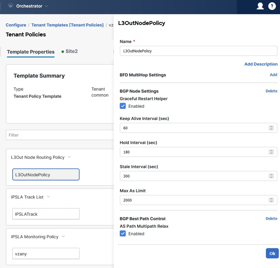
The following MOs are grouped into an L3Out Node Routing policy on NDO:
-
BGP Timer Policy
-
BGP Best Path Policy
-
BFD Multi-Hop Node Policy
The following figure shows the L3Out Node Routing Policy object in NDO that groups together the 3 policies mentioned above:
-
-
The following MOs are grouped into an L3Out Interface Routing policy on NDO:
-
OSPF Interface Policy
-
BFD Policy
-
BFD Multi-Hop Interface Policy
-
Automatic Import of Dependencies
Tenant Policies templates include objects and policies that have local references within the template. For example, an IPSLA track list can contain a list of track members and each track member must refer to a IPSLA monitoring policy. In such cases, importing existing configuration that contains one or more IPSLA track list policies from a site will also automatically import the referenced IPSLA monitoring policy. The import workflow displays additional information about the automatically imported policies when you select an object that has such dependencies:
References to Policies in Tenant "Common"
Some policies that you import from a site may contain references to policies in tenant common. Importing such policies will automatically create a copy of the tenant common policy in the Tenant Policies template where the objects are being imported and as a result of that, in the tenant associated with that Tenant Policies template, for example:
-
If you import an IPSLA track list that contains a track member which refers to an IPSLA monitoring policy from the
commontenant, a copy of the tenant `common’s IPSLA monitoring policy will be created in the Tenant Policies template and the imported track member will reference this newly added IPSLA monitoring policy. -
If you import an L3Out that contains node configuration with a static route which references an IPSLA track list from tenant
common, a copy of the tenant `common’s IPSLA track list will be created in the Tenant Policies template.
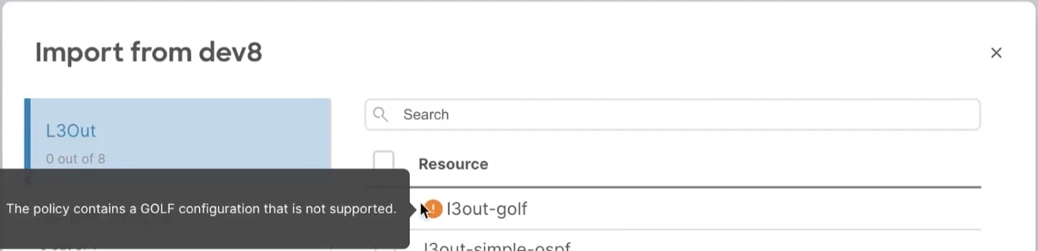
Unsupported Scenarios
If an L3Out contains one or more configuration options that are currently not supported by NDO, you will not be able to import that L3Out. The following configurations are currently not supported by NDO and will prevent you from importing any L3Out that includes them:
-
GOLF
-
EIGRP
In these cases, the import workflow UI will display an orange exclamation point icon with a message explaining the issue and you will not be able to select that L3Out for import:
Importing Tenant Policies Template Objects
-
If you want to configure and deploy new SR-MPLS L3Out configurations (greenfield deployment), see the earlier sections of this chapter instead.
-
You must have the Cisco Nexus Dashboard Orchestrator service that is installed and enabled.
-
You must have the fabrics on board to your Cisco Nexus Dashboard and enabled for management in the Orchestrator service.
-
Ensure you have read and understood the Templates and Policy Objects dependencies that are described in Overview of Importing SR-MPLS Configuration.
This section describes how to import existing SR-MPLS L3Out configuration policies from Cisco APIC into NDO’s Tenant Policies template. For more information about each policy and how it relates to policies and settings in other templates, see Overview of Importing SR-MPLS Configuration.
-
Log in to your Cisco Nexus Dashboard and open the Orchestrator service.
-
In the left navigation pane, choose Configure > Tenanat Template > Tenant Policies.
-
In the main pane, click Add Tenant Policy Template.
If you want to update an existing Tenant Policy template instead, simply click its name. This opens the Tenant Policies page.
-
If you created a brand new template, provide the Name for the template and Select a Tenant from which you plan to import configuration.
-
Associate the template with the site from which you plan to import configuration.
-
In the Tenant Policies template view, choose Actions > Add/Remove Sites.
-
In the Add Sites to <template-name> dialog, select the sites to which you want to deploy the template.
-
-
Click Save to save the template changes.
-
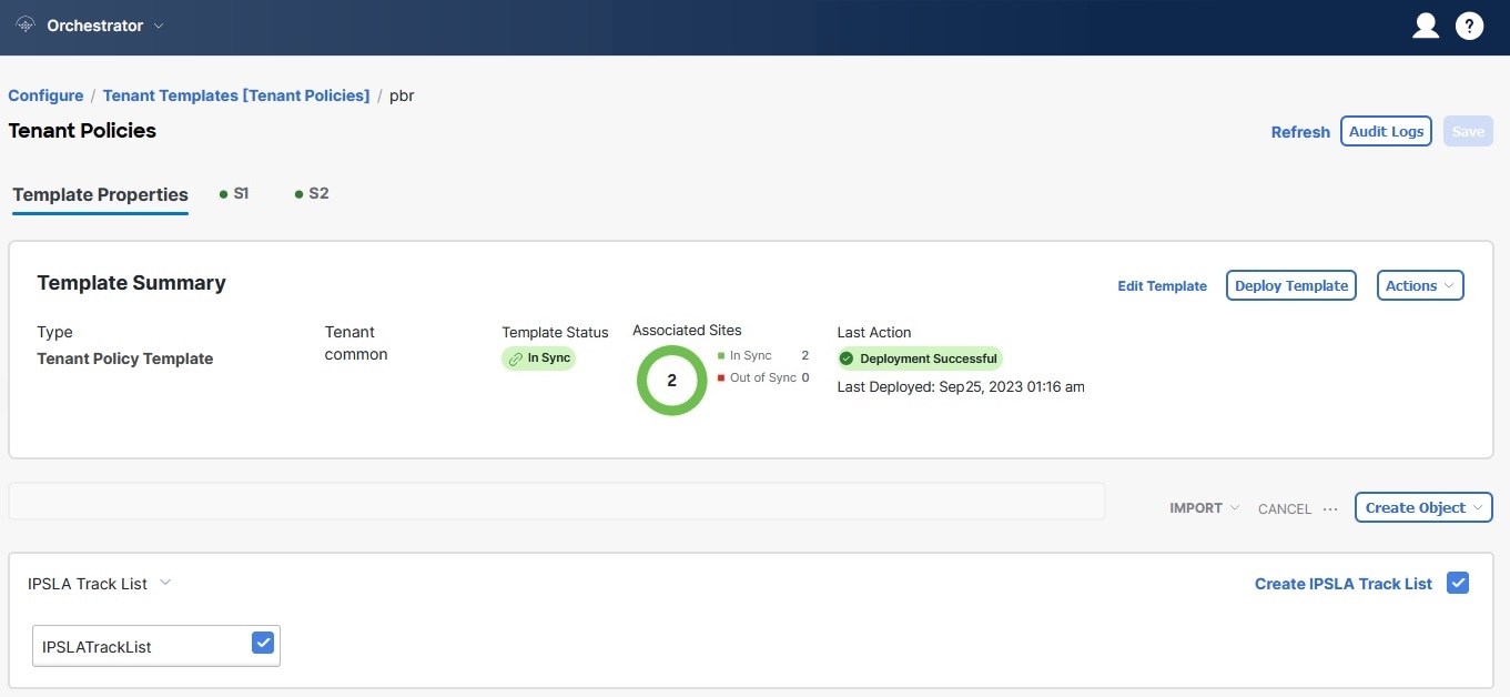
Import one or more policies into the Tenant Policies template.
When you choose to import L3Out configuration from a site, the UI shows the list of L3Out policies that can be imported. You may select one or more L3 out policies and import all the provider policies that are used by the L3 out into this Tenant Policy Template.
-
In the Tenant Policies screen’s Template Properties view, choose Import<site-name>.
-
In the Import from <site-name> dialog, choose one or more L3Outs and click Import.
If there’s an SR-MPLS L3Out already configured in the site, its associated policies are available for import in the L3OutSources category. When you select an L3OutSource to import, all policies that are referenced by that L3Out in the site’s APIC are imported into the Tenant Policies template you are editing.
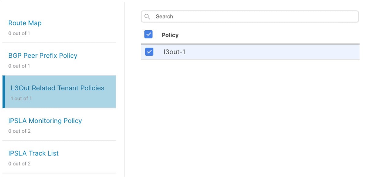 Figure 8. Import Tenant Policies
 -
Verify that all imported policies are shown in the template and click Save to save it.
All policies configured for the L3Out in the site, which you chose to import in the previous step, are added to the Tenant Policies template using the following guidelines:
-
Default import route maps are named as
<l3out-name>_di. -
Default export route maps are named as
<l3out-name>_de. -
Node routing policies are named as
<l3out-name>_<node-profile-name>. -
Interface routing policies are named as
<l3out-name>_<interface-profile-name>.
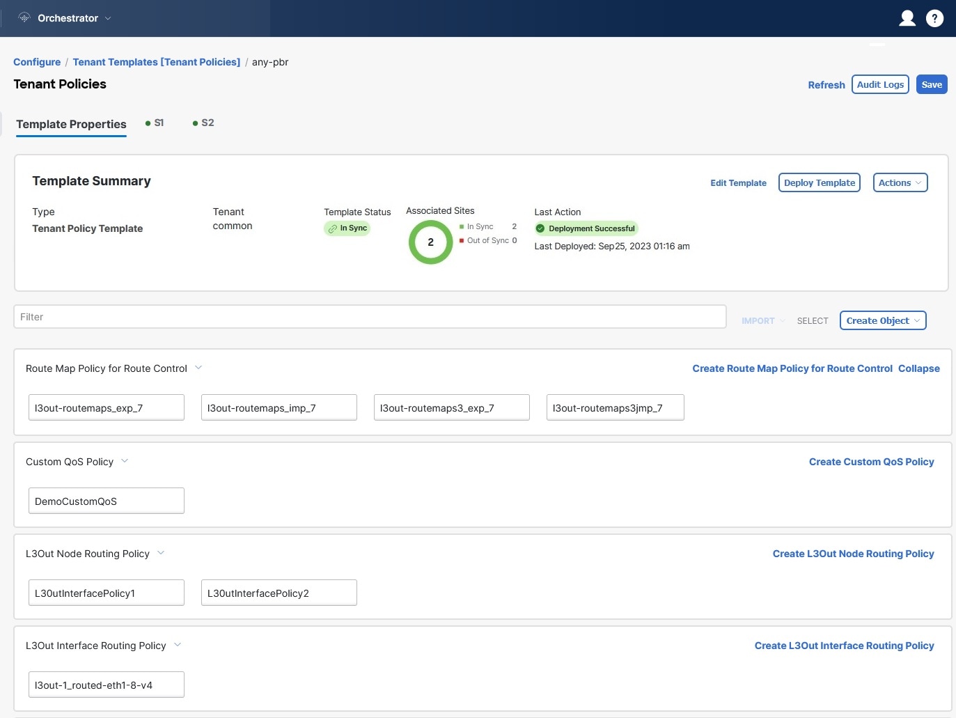 Figure 9. Tenant Policies
 -
-
If necessary, update the policy names and click Save to save the changes.
We recommend keeping the names of the imported policies as they are created. In this case, when you import L3Outs into the L3Out template as described in the next section, the referenced policies will be automatically recognized and configured for the L3Out by NDO.
However, if you have a specific naming convention in your Multi-Site domain, you can update the imported objects' names to follow that convention. In this case, you must manually provide object references during L3Out import in the next section.
For some objects, there is no 1:1 mapping between the managed objects (MOs) created in the site and the policy objects as they are seen on and managed by the Orchestrator. For information about which MOs are combined into logical groups in NDO, see !!!Dita2Adoc_MissingReference:!!!.
-
-
Deploy the template to sites.
After you have imported the policies and saved the template, you must deploy it back to the site.
-
In the Tenant Policies template view, click Deploy.
-
In the Deploy to sites dialog, confirm the policies being deployed and click Deploy.
-
After you’ve defined the policies in the Tenant Policy template, proceed to Importing SR-MPLS Objects.
Importing SR-MPLS Objects
-
If you want to configure and deploy new L3Out configurations (greenfield deployment), see the earlier sections of this chapter instead.
-
You must have created a Template Policy template and imported the policies that are associated with the L3Out you want to import, as described in Importing Tenant Policies Template Objects.
This section describes how to import an L3Out template from an APIC site into Cisco Nexus Dashboard Orchestrator. For more information about each policy and how it related to policies and settings in other templates, see Overview of Importing SR-MPLS Configuration.
-
In the left navigation pane, choose Configure > Tenant TemplateL3Out.
-
In the main pane, click Create L3Out Template.
If you want to update an existing L3Out template instead, simply click its name. This opens the L3Out Template page.
-
If you are creating a brand new template, choose the Tenant and Site from which you import the L3Out configuration, then click Save and go to template.
Each L3Out template is associated with a specific tenant similar to other NDO templates, however it is also assigned to a single site only as L3Out configuration is typically site-specific.
If you want to import SR-MPLS L3Out configuration for multiple sites, you must create at least one L3Out template for each site, but you can import multiple SR-MPLS L3Outs per site/tenant into the same template or you may choose to have multiple SR-MPLS L3Out templates per site as long as they are assigned to different tenants.
-
If you created a brand new template, provide the Name for the template and click Save.
You must save new templates before you can add new or import existing configuration.
-
Import an SR-MPLS L3Out from the site.
-
In the main pane, click Import.
-
In the Import from <site-name> dialog, select the SR-MPLS L3Out you want to import and click Import.
Some SR-MPLS L3Outs may be listed with a warning icon. Typically, this means that the associated tenant policies references are not found in NDO Tenant Policies templates and you must first import those references as described in Importing Tenant Policies Template Objects.
If you choose to import an L3Out before importing the policies it references and then redeploy that SR-MPLS L3Out to the site, the existing configuration will be removed and the SR-MPLS L3Out will be redeployed from NDO resulting in a loss of any policies that are referenced by the SR-MPLS L3Out that were not imported into NDO.
-
-
Click Save to save the template changes.
-
Deploy the template to site.
After you have imported the L3Out and saved the template, you must deploy it back to the site.
-
In the L3Out Template page, click Deploy.
-
In the Deploy to sites dialog, confirm the policies being deployed and click Deploy.
-
First Published: 2024-03-01
Last Modified: 2024-03-01
Americas Headquarters
Cisco Systems, Inc.
170 West Tasman Drive
San Jose, CA 95134-1706
USA
http://www.cisco.com
Tel: 408 526-4000
800 553-NETS (6387)
Fax: 408 527-0883