
Fabric Management Templates
Beginning with release 4.0(1), Cisco Nexus Dashboard Orchestrator allows you to configure several fabric policies, fabric resource policies, and monitoring policies. Similarly to how you create objects and define configuration for VRFs, BDs, or EPGs using Schemas and Application Templates, these new policies are defined in their respective template types. The following sections describe the policies that you can now configure directly from NDO and the steps that are required to do so.
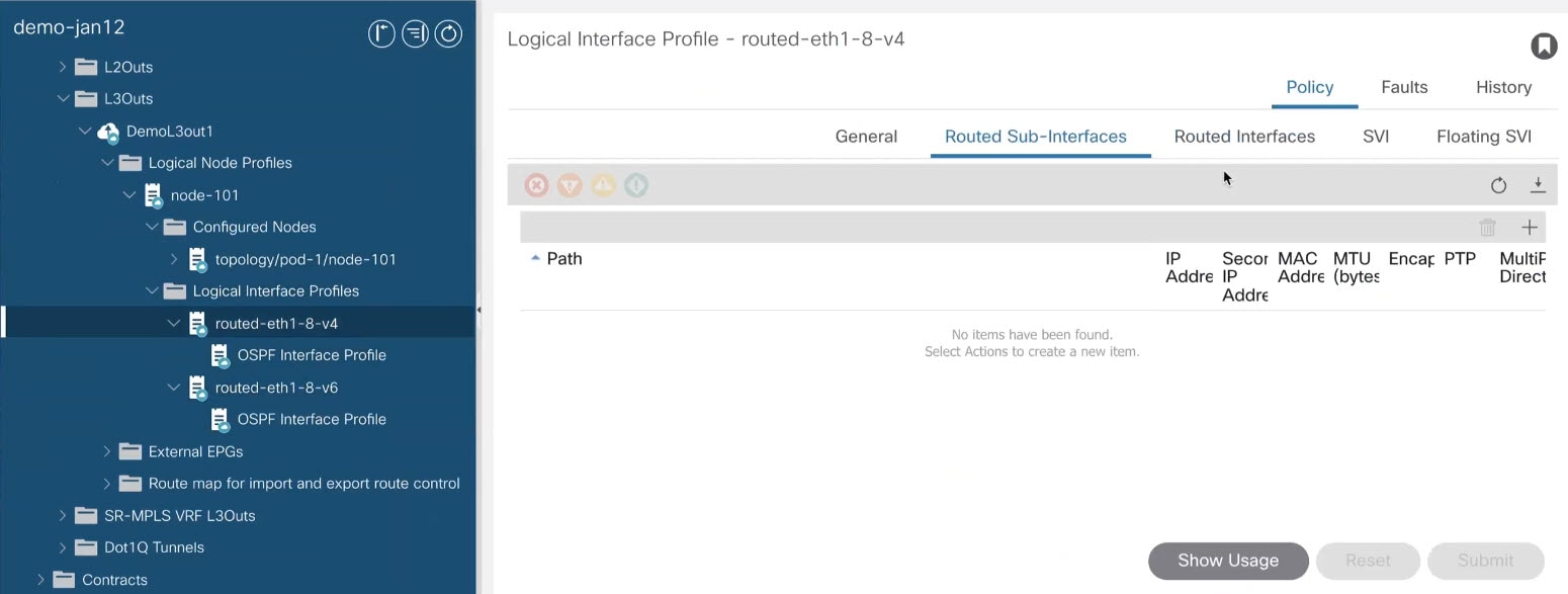
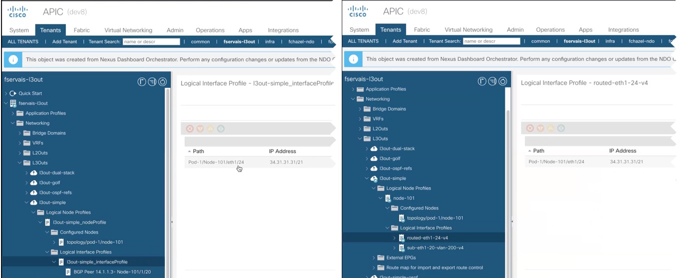
While the objects you define in the Application templates map one-to-one to the same managed objects (MOs) in the site’s APIC, the new template types group some objects and policies into logical containers. In these cases, after you define all the required policies within the same logical container in one of the new template types in NDO, individual policies are still created in the APIC when you deploy that configuration from the Orchestrator. For example, separate policies are created for the nodes, interfaces, and even IP address types, so providing IPv4 and IPv6 IP addresses for a single L3Out interface creates two separate interface profiles in the APIC:

Because of how NDO maintains these logical containers with multiple individual policies, it also enforces specific best practices for the policy model in the APIC during template deployment. This can result in a scenario where if you import some previously existing configuration from the APIC into one of the new templates, edit the configuration, and then redeploy, the old MOs are removed and new ones are created with NDO-specific hierarchy, which may cause a brief (up to 1 second) traffic interruption:
This happens only if the imported objects are modified and redeployed. If you simply import the configuration and immediately redeploy it without any changes, NDO will simply take ownership of the MOs in the APIC but will not remove or recreate them.
Creating Fabric Policies
This section describes how to create one or more fabric policy templates. Fabric policy templates allow you to create and configure the following fabric policies:
-
VLAN Pool
-
Physical Domains
-
L3 Domains
-
SyncE Interface Policies
-
Interface Settings
-
Node Settings
-
Pod Settings
-
MACsec
-
NTP Policies
-
PTP Policies
-
QoS DSCP Policies
-
QoS SR-MPLS Policies
-
QoS Class Policies
-
MCP Global Policies
When creating Fabric Policy templates policies, consider the following:
-
Fabric Policy templates do not need to be associated to any tenant, but must be mapped to at least one site to be deployed.
-
The configuration of those policies is only possible at the template level and not at the specific site level.
-
Undeploying a Fabric Policy template would result in preservation of the associated policies on APIC. In other words, the configuration of those policies on APIC won’t be reverted to the default values or to the values that were configured on the APIC before the Orchestrator began managing them.
-
Log in to your Cisco Nexus Dashboard and open the Cisco Nexus Dashboard Orchestrator service.
-
Create a new Fabric Policy template.
-
From the left navigation pane, choose Configure > Fabric Policies.
-
On the Fabric Policy Templates page, click Create Fabric Policy Template.
-
In the Fabric Policies page’s right properties sidebar, provide the Name for the template.
By default, the new template is empty, so you must add one or more fabric policies as described in the following steps. You don’t have to create every policy available in the template - you can define one or more policies of each type to deploy along with this template. If you don’t want to create a specific policy, simply skip the step that describes it.
-
-
Assign the template to one or more sites.
The process for assigning Tenant Policy templates to sites is identical to how you assign application templates to sites.-
In the Template Properties view, click Actions and choose Add/Remove Sites.
The Associate Sites to <template-name> window opens. -
In the Associate Sites window, check the check box next to the sites where you want to deploy the template.
Only the on-premises ACI sites support tenant policy templates and will be available for assignment. -
Click Ok to save.
-
-
Create a VLAN Pool.
A VLAN pool specifies the VLAN IDs or ranges that are used for VLAN encapsulation that the physical or VMM domains consume.-
From the +Create Object drop-down, select VLAN Pool.
-
In the right properties sidebar, provide the Name for the policy.
-
(Optional) Click Add Description and provide a description for the policy.
-
Click +Add VLAN Range, provide the range, and click the check mark icon to save it.
-
Repeat the previous substep to create any additional VLAN ranges within the same policy.
-
Repeat this step to create any additional VLAN pools.
-
-
Create a Physical Domain.
Physical domain profiles are typically used for bare metal server attachment and management access. A domain is configured to be associated with a VLAN pool. EPGs are then configured to use the VLANs associated with a domain.-
From the +Create Object drop-down, select Physical Domain.
-
In the right properties sidebar, provide the Name for the domain.
-
(Optional) Click Add Description and provide a description for the policy.
-
Click Select a VLAN Pool Policy and choose one of the VLAN pools for this domain.
The VLAN pool must be already created as described in Step 3. -
Repeat this step to create any additional Physical Domains.
-
-
Create an L3 Domain.
An L3 Domain profile is a policy for managing the physical infrastructure, such as ports and VLANs that can be used to connect the ACI fabric to a Layer 3 routed outside network.-
From the +Create Object drop-down, select L3 Domains.
-
In the right properties sidebar, provide the Name for the domain.
-
(Optional) Click Add Description and provide a description for the policy.
-
(Optional) Click Select a VLAN Pool Policy and choose one of the VLAN pools for this domain.
If you plan to use point-to-point routed interfaces, no VLAN Pool is necessary and you can skip this step.
However, if you configure subinterfaces or SVIs, you must provide the required VLANs by adding a VLAN Pool. In this case, the VLAN pool must be already created as described in Step 3. -
Repeat this step to create any additional L3 Domains.
-
-
Create a SyncE Interface Policy.
With Ethernet equipment gradually replacing Synchronous Optical Networking (SONET) and Synchronous Digital Hierarchy (SDH) equipment in service-provider networks, frequency synchronization is required to provide high-quality clock synchronization over Ethernet ports. Frequency or timing synchronization is the ability to distribute precision frequency around a network. Synchronous Ethernet (SyncE) provides the required synchronization at the physical level. In SyncE, Ethernet links are synchronized by timing their bit clocks from high-quality, stratum-1-traceable clock signals in the same manner as SONET/SDH.
For detailed information on SyncE in ACI fabrics, see the Synchronous Ethernet (SyncE) chapter of the Cisco APIC System Management Configuration Guide for your release.-
From the +Create Object drop-down, select SyncE Interface Policy.
-
In the right properties sidebar, provide the Name for the policy.
-
(Optional) Click Add Description and provide a description for the policy.
-
Provide policy details.
-
Admin State - Enables or disables the policy.
Default is
disabled. -
Sync State Msg - If unchecked, disables sending ESMC packets and also ignores any received ESMC packets.
-
Selection Input - Enables configuration of the priority of the frequency source on an interface.
-
Src Priority - The priority of the frequency source on an interface. This value is used in the clock-selection algorithm to choose between two sources that have the same QL.
Values can range from 1 (highest priority) to 254 (lowest priority). The default value is 100.
Can be configured only if Selection Input is enabled.
-
Wait To Restore - The wait-to-restore time, in minutes, is the amount of time after the interface comes up before it is used for frequency synchronization on an interface. Values can range 0-12 minutes. The default value is 5.
Can be configured only if Selection Input is enabled.
-
-
Repeat this step to create any additional SyncE Interface policies.
-
-
Create an Interface Settings policy.
If you want to configure SyncE or MACsec for this interface, you must have those policies that are already created as described in corresponding steps.
An interface settings policy allows you to define a set of common interface settings which you can later deploy to one or more ports on one or more switches for consistent configuration across them.
-
From the +Create Object drop-down, select Interface Settings.
-
Choose the Type of the interface that you are configuring.
-
In the right properties sidebar, provide the Name for the policy.
-
(Optional) Click Add Description and provide a description for the policy.
-
Provide policy details.
-
Speed - The data transfer rate for the port. This should match the destination to which the port is linked. The speed can be changed only for certain ports, and not all speeds are available on all systems. For more information, see the Hardware Installation Guide for your specific switch node.
-
Auto-Negotiation - Enables autonegotiation for port.
-
VLAN Scope - The Layer 2 Interface VLAN scope.
Global scope- Sets the VLAN encapsulation value to map only to a single EPG per leaf switch.Port Local scope- Allows allocation of separate (port, VLAN) translation entries in both ingress and egress directions. This configuration is not valid when the EPGs belong to a single bridge domain. -
CDP Admin State - Enables Cisco Discovery Protocol (CDP) on the interface.
-
LLDP - Enables Link Layer Discovery Protocol (LLDP) on the interface
-
MCP Admin State - Enables mis-cabling protocol (MCP) on the interface.
-
Domains - Choose one or more domains with which you want to associate this interface policy.
Specifying a domain is not mandatory, the interface policy can be created and deployed to sites without an associated domain.
-
Advanced Settings - Click the arrow next to this section to expand.
-
SyncE - If you want to have a SyncE policy that is defined and want to assign it to this interface settings policy, select it from the drop-down.
-
Debounce Interval - The port debounce time is the amount of time that an interface waits to Notify the supervisor of a link going down. During this time, the interface waits to see if the link comes back up.
-
Bring Up Delay - Specifies a time in milliseconds that the decision feedback equalizer (DFE) tuning is delayed when a port is coming up. The delay is used to help avoid CRC errors during link bringup when using some third-party adapters.
You should set the delay only as required; usually, you do not need to set a delay.
-
FEC - Forwarding Error Correction (FEC) is a method of obtaining error control in data transmission over an unreliable or noisy channel in which the source (transmitter) encodes the data in a redundant way using Error Correcting Code and the destination (receiver) recognizes it and corrects the errors without needing a retransmission.
-
QinQ - Enables mapping double-tagged VLAN traffic ingressing on a regular interface, computer, or vPC to an EPG. When this feature is enabled and double-tagged traffic enters the network for an EPG, both tags are processed individually in the fabric and restored to double-tags when egressing the ACI switch. Ingressing single-tagged and untagged traffic is dropped.
-
Reflective Relay - Forwards all traffic to an external switch, which then applies policy and sends the traffic back to the destination or target VM on the server as needed. There is no local switching. For broadcast or multicast traffic, reflective relay provides packet replication to each VM locally on the server.
One benefit of reflective relay is that it leverages the external switch for switching features and management capabilities, freeing server resources to support the VMs. Reflective relay also allows policies that you configure on the Cisco APIC to apply to traffic between the VMs on the same server.
In the Cisco ACI, you can enable reflective relay, which allows traffic to turn back out of the same port it came in on. You can enable reflective relay on individual ports, port channels, or virtual port channels as a Layer 2 interface policy.
The default value is disabled.
-
LLDP Transmit State - Allows Link Layer Discovery Protocol (LLDP) packets to be sent from the interface.
LLDP Receive/Transmit State flags can be configured only if LLDP is globally enabled in the Interface policy.
-
LLDP Receive State - Allows LLDP packets to be received by the interface.
-
BPDU Filter - Bridge Protocol Data Unit (BPDU) filter filters out any BPDUs on the port.
BPDU Filter prevents both inbound and outbound BPDUs - the received BPDUs are dropped and no BPDUs are sent out.
-
BPDU Guard - BPDU guard prevents the port from receiving BPDUs; if any BPDUs are received on the port, the port is put into
errdisablemode. -
LLFC Transmit State - Allows Link Level Flow Control (LLFC) packets to be sent from the interface.
-
LLFC Receive State - Allows LLFC packets to be received by the interface.
-
Access MACsec Policy - If you want to have an access MACsec policy that is defined and want to assign it to this interface settings policy, select it from the drop-down.
-
-
-
Repeat this step to create any additional Interface Settings policies.
-
-
Create a Node Settings policy.
A node settings policy allows you to define a set of common node settings which you can later deploy to one or more switches for consistent configuration across them.
In this release, the Node Settings policy supports enabling SyncE and PTP functionalities.-
From the +Create Object drop-down, select Node Settings.
-
In the right properties sidebar, provide the Name for the policy.
-
(Optional) Click Add Description and provide a description for the policy.
-
If you want to deploy SyncE configuration to the nodes, enable SyncE and provide the settings.
For detailed information about SyncE, see the "Synchronous Ethernet (SyncE)" chapter of the Cisco APIC System Management Configuration Guide for your release.-
Admin State - Enables or disables the policy.
-
Quality Level Option - Specifies the accuracy of the clock. This information is transmitted across the network using SSMs carried by ESMC and is used to determine the best available source to which the devices in the system can synchronize.
-
-
If you want to deploy PTP configuration to the nodes, enable PTP and provide the settings.
For detailed information about PTP, see the "Precision Time Protocol" chapter of the Cisco APIC System Management Configuration Guide for your release.
-
Repeat this step to create any additional Node Settings policies.
-
-
Create a Pod Settings policy.
Before you can create a Pod settings policy, you must have an NTP policy that is already created for it as described in the corresponding step.
If you want to configure a Pod-wide MACsec policy, you must have a MACsec policy already created as described in the corresponding steps.
A Pod settings policy allows you to define a set of common Pod settings which you can later deploy to one or more Pods in your fabric for consistent configuration across them.
-
From the +Create Object drop-down, select Pod Settings.
-
In the right properties sidebar, provide the Name for the policy.
-
(Optional) Click Add Description and provide a description for the policy.
-
Click Select a NTP Policy and choose the NTP policy.
-
From the Fabric MACsec Policy drop-down, select the MACsec policy.
-
Repeat this step to create any additional Pod Settings policies.
-
-
Create a MACsec policy.
MACsec provides MAC-layer encryption over wired networks by using out-of-band methods for encryption keying. The MACsec Key Agreement (MKA) Protocol provides the required session keys and manages the required encryption keys.
For detailed information on MACsec in ACI fabrics, see the "MACsec" chapter of the Cisco APIC System Management Configuration Guide for your release.
-
From the +Create Object drop-down, select MACsec.
-
In the right properties sidebar, provide the Name for the policy.
-
(Optional) Click Add Description and provide a description for the policy.
-
Provide policy details.
-
Type - Defines the type of the interfaces that this policy will be applied to.
All the links on a spine switch are considered to be fabric links. However, if a spine switch link is used for IPN connectivity, then this link will be treated as an access link. This means that a MACsec access policy must be used to deploy MACsec on these links.
-
Admin State - Enables or disables the policy.
-
Cipher Suite - When selecting the cipher suite AES 128 or AES 256 without Extended Packet Numbering (XPN), you must explicitly specify the Security Association Key (SAK) expiry time. Leaving the SAK expiry time value at the default ("disabled") can cause interfaces to go out of service randomly.
-
Window Size - A replay window is necessary to support the use of MACsec over provider networks that reorder frames. Frames within the window can be received out of order, but are not replay that is protected. The default window size is 64. The replay window size can be configured in the range of 0 to 232-1 if you use the Cisco APIC GUI or CLI. If you use an XPN cipher suite, the maximum replay window size is 230-1, and if you configure a higher window size, the window size gets restricted to 230-1. If you change the cipher suite to a non-XPN cipher suite, then there is no restriction and the configured window size is used.
-
Security Policy - APIC MACsec supports two security modes. The MACsec
Must-Secureonly allows encrypted traffic on the link while theShould-Secureallows both clear and encrypted traffic on the link. For example, a port can turn on MACsec inMust-Securemode before its peer has received its keychain resulting in the link going down. To address this issue, the recommendation is to deploy MACsec inShould-Securemode and when all the links are up then change the security mode toMust-Secure.
Before deploying MACsec in
Must-Securemode, the keychain must be deployed on the affected interface or the interface will go down.
-
SAK Expiry Time - When selecting the cipher suite AES 128 or AES 256 without Extended Packet Numbering (XPN), you must explicitly specify the Security Association Key (SAK) expiry time. Leaving the SAK expiry time value at the default can cause interfaces to go out of service randomly.
-
Key Name - Allows you to create a MACsec key. APIC is responsible for the MACsec keychain distribution to all the nodes in a Pod or to particular ports on a node.
-
Click +Add MACsec Key.
-
Provide the Key Name.
-
Provide the pre-shared key in the PSK field.
-
In the Start Time field, provide the date for the key to become valid.
-
In the End Time field, provide the date for the key to expire.
-
Click Ok to save the key.
-
Repeat the steps for any additional keys that you want to provide.
-
-
-
Repeat this step to create any additional MACsec policies.
-
-
Create an NTP Settings Policy.
Within the ACI fabric, time synchronization is a crucial capability upon which many of the monitoring, operational, and troubleshooting tasks depend. Clock synchronization is important for proper analysis of traffic flows and for correlating debug and fault timestamps across multiple fabric nodes.
For detailed information on NTP in ACI fabrics, see the "Provisioning Core ACI Cisco Fabric Services" chapter of the Cisco APIC Basic Configuration Guidefor your release.
-
From the +Create Object drop-down, select NTP Settings.
-
In the right properties sidebar, provide the Name for the policy.
-
(Optional) Click Add Description and provide a description for the policy.
-
Provide policy details.
-
Click +Add Key to provide the NTP client authentication key.
-
Advanced Settings - Click the arrow next to this section to expand.
-
Admin State - Enables or disables the NTP policy.
-
Server State - Enables the ACI leaf switches to act as NTP servers to provide NTP information to downstream clients.
When enabled, the downstream clients can use the in-band/out-of-band management IP address of the leaf switch to which they are connected as the NTP server.
-
Master Mode - Enables the designated NTP server to provide undisciplined local clock time to downstream clients with a configured stratum number. For example, a leaf switch that is acting as the NTP server can provide undisciplined local clock time to leaf switches acting as clients. This is only applicable when the server clock is undisciplined.
-
Stratum - Specifies the stratum level from which NTP clients get their time synchronized.
If the Server State option is enabled and clients that are connected to an ACI leaf switch are configured to use the switch’s management IP address as NTP server, they receive NTP information with stratum+1.
The range is 1-14.
-
Authentication State - Enables certificate-based authentication.
If you enable this option, you must provide the key using the +Add Key option above.
-
-
Click +Add Provider to specify the NTP server information.
In the Add Provider window that opens, you must provide the server’s Host name / IP Address, the name of the Management EPG, and the Management EPG Type.
The management EPG with the specific type that you choose must be already configured in the APICs of the sites with which this template is associated.
If you are creating multiple providers, check the Preferred option for the most reliable NTP source.
-
-
Repeat this step to create any additional NTP Settings policies.
-
-
Create a PTP Settings policy.
The Precision Time Protocol (PTP) is a time synchronization protocol for nodes that are distributed across a network. With PTP, you can synchronize distributed clocks with an accuracy of less than 1 microsecond using Ethernet networks. PTP’s accuracy comes from the hardware support for PTP in the ACI fabric spine and leaf switches.
For detailed information on PTP in ACI fabrics, see the "Precision Time Protocol" chapter of the Cisco APIC System Management Configuration Guide for your release.
-
From the +Create Object drop-down, select PTP Settings.
-
In the right properties sidebar, provide the Name for the policy.
-
(Optional) Click Add Description and provide a description for the policy.
-
Provide policy details.
-
Admin State - Enables or disables the policy.
-
Global Priority 1 - Specifies a value that is used when advertising this clock. Priority 1 overrides the default criteria (such as clock quality and clock class) for best primary clock selection.
Valid values are from 0 to 255. The default is 128. Lower values take precedence.
-
Global Priority 2 - Specifies a value that is used when advertising this clock. Priority 2 is used as a tie-breaker between two devices that are otherwise equally matched in the default criteria.
Valid values are 0-255 . The default is 128. Lower values take precedence.
-
Global Domain - Specifies the PTP domain number. Although multiple PTP domains are not supported in Cisco ACI, you can still change the domain number in use. The same value is used on all leaf switch and spine switches.
Valid values are 0-128. The default is 0.
-
Fabric Profile Template - Specifies the PTP profile that defines the default values for the interval settings below. Profiles are used to define various parameters that are optimized for different use cases of PTP. Some of those parameters include, but not limited to, the appropriate range of PTP message intervals and the PTP transport protocols. A PTP profile is defined by many organizations/standards in different industries.
-
AES67-2015: AES67-2015, which is the standard for audio over Ethernet and audio over IP interoperability.
-
Default: IEEE 1588-2008, which is the default PTP profile for clock synchronization.
-
SMPTE-2059-2: SMTPE ST2059-2015, which is the standard for video over IP.
-
Telecom-8275-1: ITU-T G.8275.1, which is the standard recommendation for telecommunications with Full Timing Support.
Full Timing Support is the term that is defined by ITU to describe a telecommunication network that can provide devices with PTP G.8275.1 profile on every hop. G.8275.2, which is not supported by ACI, is for Partial Timing Support that may have devices in the path that do not support PTP.
-
-
Fabric Announce Interval - Specifies the logarithm of the mean interval in seconds with base 2 for a primary port to send announce messages. The range depends on the chosen profile.
-
Fabric Sync Interval - Specifies the logarithm of the mean interval in seconds with base 2 for a primary port to send synchronization messages. The range and the default depend on the chosen PTP profile.
-
Fabric Delay Interval - Specifies the logarithm of the mean interval in seconds with base 2 for a slave port to send delay request messages. The range depends on the chosen PTP profile.
-
Fabric Announce Timeout - Specifies the number of announce messages that the system waits before the PTP announce that message is considered expired. The range and the default depend on the chosen PTP profile.
-
Advanced Settings - Click the arrow next to this section to expand. how are profiles added here different from the one selected above?
-
Click +Add Profile to add a PTP profile. Profiles are used to define various parameters that are optimized for different use cases of PTP. Some of those parameters include, but not limited to, the appropriate range of PTP message intervals and the PTP transport protocols. A PTP profile is defined by many organizations/standards in different industries.
-
In the Add Profile dialog, provide the Name.
-
From the Profile Template drop-down, select one of the available profiles.
Detailed information about the profiles is available in the Cisco APIC System Management Configuration Guide.
-
Update the default profile values as required by your specific use case.
-
-
-
Repeat this step to create any additional PTP Settings policies.
-
-
Create a QoS DSCP policy.
This policy is part of the overarching QoS preservation across IPN use case. You can use the information in this section as a reference, but we recommend following the full set of steps described in the QoS Preservation Across IPN chapter.
-
From the +Create Object drop-down, select QoS DSCP.
-
In the right properties sidebar, provide the Name for the policy.
-
(Optional) Click Add Description and provide a description for the policy.
-
Provide policy details.
-
Admin State - Enables or disables the policy.
-
Advanced Settings - Click the arrow next to this section to expand.
Choose the DSCP value for each ACI QoS level. Each drop-down contains the default list of available DSCP values. You must choose a unique DSCP value for each level.
-
-
Repeat this step to create any additional QoS DSCP policies.
Typically, we recommend applying this policy consistently across all sites that are part of your Multi-Site domain.
-
-
Create a QoS SR-MPLS policy.
This policy is part of the overarching SR-MPLS use case. You can use the information in this section as a reference, but we recommend following the full set of steps that are described in the Multi-Site and SR-MPLS L3Out Handoff chapter of the Features and Use Cases section of this document.
-
From the +Create Object drop-down, select QoS SR-MPLS.
-
In the right properties sidebar, provide the Name for the policy.
-
(Optional) Click Add Description and provide a description for the policy.
-
Click +Add Ingress Rule to add an ingress QoS translation rule.
These rules are applied for traffic that is ingressing the ACI border leaf switches from an MPLS network and are used to map incoming packet’s experimental bits (EXP) values to ACI QoS levels, as well as to set differentiated services code point (DSCP) or CoS values for the original traffic. To ensure that the specified CoS value is used for traffic egressing an ACI leaf node, you must also configure CoS preservation feature as part of the "QoS Class Policies".
If a custom policy is not defined or not matched, default QoS Level (Level 3) is assigned.-
In the Match EXP From and Match EXP To fields, specify the EXP range of the ingressing MPLS packet you want to match.
-
From the Queuing Priority drop-down, select the ACI QoS Level to map.
This is the QoS Level that you want to assign for the traffic within ACI fabric, which ACI uses to prioritize the traffic within the fabric. The options range from
Level 1toLevel 6. The default value isLevel 3. If you do not make a selection in this field, the traffic will automatically be assigned aLevel 3priority. -
From the Set DSCP drop-down, select the DSCP value to assign to the traffic when it will be sent out of the destination ACI leaf switch.
The DSCP value specified is set in the original traffic that is received from the external network, so it will be reexposed only when the traffic is VXLAN decapsulated on the destination ACI leaf node.
If you set the value to
Unspecified, the original DSCP value of the packet will be retained. -
From the Set CoS drop-down, select the CoS value to assign to the traffic when it will be sent out of the destination ACI leaf switch.
The CoS value that is specified is set for traffic egressing the destination ACI leaf switch. This requires CoS preservation to be enabled.
If you set the value to
Unspecified, the original CoS value of the packet will be retained, but only if the CoS preservation option is enabled in the fabric. For more information about CoS preservation, see Cisco APIC and QoS. -
Click the check mark icon to save the rule.
-
Repeat these steps for any additional ingress QoS policy rules within the same policy.
-
-
Click Add Egress Rule to add an egress QoS translation rule.
These rules are applied on the border leaf switches for the traffic that is leaving the ACI fabric through an MPLS L3Out and are used to match the DSCP value of the packet and, if a match is found, set the MPLS EXP and CoS values based on the configured policy.
If a custom policy is not defined or not matched, the default EXP value of
0is marked on all labels. EXP values are marked in both, default and custom policy scenarios, and are done on all MPLS labels in the packet.Custom MPLS egress policy can override existing EPG, L3Out, and Contract QoS policies.
-
Using the Match DSCP From and Match DSCP To dropdowns, specify the DSCP range that you want to match for assigning the egressing MPLS packet’s priority.
-
From the Set MPLS EXP drop-down, select the EXP value that you want to assign to the egressing MPLS packet.
-
From the Set CoS drop-down, select the CoS value that you want to assign to the egressing MPLS packet.
-
Click the check mark icon to save the rule.
-
Repeat these steps for any additional egress QoS policy rules.
-
-
Repeat this step to create any additional QoS SR-MPLS policies.
-
-
Create a QoS Class Policies policy.
Cisco ACI provides several user-configurable QoS levels. Cisco APIC, Release 4.0(1) and latter supports 6 user-configurable QoS levels, while earlier releases supported 3. This step describes how to configure specific settings for each of these levels using the Cisco Nexus Dashboard Orchestrator.
For detailed information about QoS functionality in ACI fabrics, see Cisco APIC and QoS.
The most common use case for these policies is to enable CoS preservation for traffic coming into your ACI fabric.
-
From the +Create Object drop-down, select QoS Class Policies.
-
In the right properties sidebar, provide the Name for the policy.
-
(Optional) Click Add Description and provide a description for the policy.
-
If necessary, enable Preserve CoS.
When traffic enters the ACI fabric, based on the configured QoS policy, each packet can be mapped to an ACI QoS level. These QoS levels are then stored in the CoS field and DE bit of the packet’s outer header while the original headers are discarded. If you want to preserve the original CoS values of the ingressing packets and restore it when the packet leaf switches the fabric, you can use this setting to enable the 802.1p Class of Service (CoS) preservation.
-
Click +Add Level to define configuration details for a specific QoS class.
The Add QoS Level Configuration windows opens.
-
In the Add QoS Level Configuration window, choose the QoS Level you want to configure and provide the configuration details.
-
MTU - The maximum transmission unit to be used for packets of this QoS class.
-
Minimum Buffer - The minimum number of reserved buffers. The number can be from 0 through 3.
The default value is 0.
-
Congestion Algorithm - The congestion algorithm used for this QoS Level.
-
Scheduling Algorithm - The scheduling algorithm used for this QoS Level.
-
Bandwidth Allocated - The percentage of total bandwidth allocated to this QoS Level. The value can be from 0 through 100.
The default value is 20.
-
PFC Admin State - The administrative state of the Priority Flow Control policy that is applied to FCoE traffic.
-
Admin State - Enables or disables the policy.
-
No Drop Cos - The CoS level to impose no drop FCoE packet handling even in case of FCoE traffic congestion.
-
PFC Scope - The Priority Flow Control (PFC) scope.
Fabric-wide PFCfor the entire fabric orIntraTor PFCfor the spine switches only.
-
-
Repeat this step to create any additional QoS Class policies.
-
-
Create an MCP Global Policy.
The mis-cabling protocol (MCP) is designed to handle misconfiguration that Link Layer Discovery Protocol (LLDP) and Spanning Tree Protocol (STP) are unable to detect. MCP uses a Layer 2 packet to detect and disable ports that form loops in the external infrastructure. You can use MCP packets to detect loops that involve the leaf switches and raise faults and events in the fabric when that occurs. MCP can be enabled globally or per-interface. By default, MCP is disabled globally and is enabled on each port, however you must enable MCP globally for it to function.
If you configure and deploy an MCP global policy to one or more fabrics and then undeploy the template, the policy remains in the sites.
-
From the +Create Object drop-down, select MCP Global Policy.
Only a single MCP Global policy can be created.
-
In the right properties sidebar, provide the Name for the policy.
-
(Optional) Click Add Description and provide a description for the policy.
-
Enable Admin State to enable the policy.
-
Enable MCP PDU per VLAN.
This enables MCP to send packets on a per-EPG basis. If this option is disabled, the packets will only be sent on untagged EPGs which allows detecting loops in the native VLAN only.
-
If you have enabled the Admin State, provide a Key to uniquely identify the MCP packets within the fabric.
-
If necessary, update the Loop Detect Multiplication Factor value.
This specifies the number of MCP packets that will be received by the ACI fabric before the Loop Protection Action occurs.
-
(Optional) Modify the additional MCP settings.
-
Initial Delay Time - the time before MCP starts taking action. From the system start until the Initial Delay Timer timeout, MCP will only create a syslog entry if a loop is detected.
-
Transmission Frequency - the transmission frequency of the MCP packets.
-
-
-
Click Save to save the changes you’ve made to the template.
-
Click Deploy to deploy the template to the associated sites.
The process for deploying tenant policy templates is identical to how you deploy application templates.
If you have previously deployed this template but made no changes to it since, the Deploy summary indicates that there are no changes, and you can choose to redeploy the entire template. In this case, you can skip this step.
Otherwise, the Deploy to sites window shows you a summary of the configuration differences that will be deployed to sites. Note that in this case only the difference in configuration is deployed to the sites. If you want to redeploy the entire template, you must deploy once to sync the differences, and then redeploy again to push the entire configuration as described in the previous paragraph.
-
Creating Fabric Resources Policies
-
Most of the fabric resource policies require one or more fabric policies, so you must have those fabric policies that are already defined as described in Creating Fabric Policies.
For example, when creating an interface policy (physical, port channel, or virtual port channel), you must have an interface settings policy already created.
-
The templates that contain the fabric policies that are required for the fabric resources policies must be deployed before any of the fabric resource policy templates.
-
The Fabric Resource Policies templates do not need to be associated to any tenant, but must be mapped to at least one site to be deployed.
-
In a typical deployment, we recommend that a separate Fabric Resource Policies template is associated to each site that is part of the Multi-Site domain.
In this case, we also recommend provisioning the configuration of the associated policies always at the global template level and not at the site level.
This section describes how to create one or more fabric resources templates. Fabric resources templates allow you to create and configure the following:
-
Physical Interfaces
-
Port Channel Interfaces
-
Virtual Port Channel Interfaces
-
Node Profiles
-
Pod Profiles
-
FEX Device
Importing policies for Fabric Resource Templates on Physical Interfaces, Port Channels (PCs), and Virtual Port Channels (VPCs) policies created through the Interface Configuration is not supported. This restriction also applies to FEX and node configurations. Only manually configured policies can be imported.
To create fabric resource policies:
-
Log in to your Cisco Nexus Dashboard and open the Cisco Nexus Dashboard Orchestrator service.
-
Create a new Fabric Resources Policy template.
-
From the left navigation pane, choose Configure > Fabric Template.
-
On the Fabric Resources Policies page, click Create Fabric Resource Template.
-
In the Resource Policies page’s right properties sidebar, provide the Name for the template.
By default, the new template is empty, so you must add one or more fabric policies as described in the following steps. You don’t have to create every policy available in the template - you can define one or more policies of each type to deploy along with this template. If you don’t want to create a specific policy, simply skip the step that describes it.
-
-
Assign the template to one or more sites.
The process for assigning Tenant Policy templates to sites is identical to how you assign application templates to sites.
-
In the Template Properties view, click Actions and choose Add/Remove Sites.
The Associate Sites to <template-name> window opens.
-
In the Associate Sites window, check the check box next to the sites where you want to deploy the template.
Only the on-premises ACI sites support tenant policy templates and will be available for assignment.
-
Click Ok to save.
-
-
Create a Physical Interfaces policy.
Before you can create a physical interfaces policy, you must have an Interface Settings (
Physical) policy that is already created for it as described in Creating Fabric Policies.-
From the +Create Object drop-down, select Physical Interface.
-
(Optional) Add Description, a short description of the policy.
-
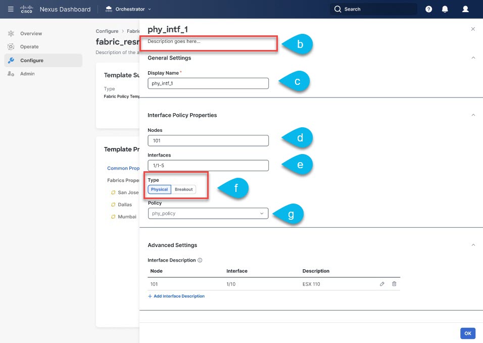
In the right properties sidebar, provide the Name for the policy.
-
In the Nodes field, provide one or more node IDs where this physical interface policy will be deployed.
The configuration of the nodes policy can be also done at the site-local view of the template. In that case, the site level configuration would override the global template level configuration. As previously mentioned, in the specific scenario where a different template is created and associated to each site that is part of the Multi-Site domain, we recommend that you configure the nodes policy only at the global template level.
For example,
101,102,103. -
In the Interfaces field, provide the interface names where the policy will be deployed.
For example,
1/1,1/2-4,1/5. -
Choose whether the interface is a Physical or a Breakout interface.
-
If you are configuring a Physical interface, click Select Physical Policy and choose the interface settings policy that you created for this.
The interface settings that are defined in the interface settings policy will be applied to the interfaces (
1/1,1/2-4,1/5) on the nodes (101,102,103) you provided in the previous substeps. -
If you are configuring a Breakout interface, choose the Breakout Mode for it.
This release supports
4x10G,4x25G, and4x100Gmodes. -
Repeat this step to create any additional Physical Interfaces policies.
A different policy could be needed, for example, when a unique set of physical interfaces should be configured on each node. In that case, you would define a unique Physical Interfaces policy for each specific node.
-
-
Create a Port Channel Interfaces policy.
Before you can create a Port Channel interfaces policy, you must have an Interface Settings (
PC/VPC) policy that is already created for it as described in Creating Fabric Policies.-
From the +Create Object drop-down, select Port Channel Interface.
-
In the right properties sidebar, provide the Name for the policy.
-
(Optional) Click Add Description and provide a description for the policy.
-
In the Node field, provide the node ID of the switch where this physical interface policy will be deployed.
The configuration of the nodes policy can be also done at the site-local view of the template. In that case, the site level configuration would override the global template level configuration. As previously mentioned, in the specific scenario where a different template is created and associated to each site that is part of the Multi-Site domain, we recommend that you configure the nodes policy only at the global template level.
For example,
104. -
In the Interfaces field, provide the interface names of the interfaces that are part of the port channel.
For example,
1/6,1/7. -
Click No selected PC/VPC Policy and choose the interface settings policy that you created for this.
The Port Channel settings that are defined in the interface settings policy will be applied to the interfaces (
1/6,1/7) on the node (104) you provided in the previous substeps. -
Repeat this step to create any additional Port Channel Interfaces policies.
A different policy could be needed, for example, when a unique set of Port Channel interfaces should be configured on each node. In that case, you would define a unique Port Channel Interfaces policy for each specific node.
-
-
Create a Virtual Port Channel Interfaces policy.
Before you can create a Virtual Port Channel interfaces policy, you must have an Interface Settings (
PC/VPC) policy that is already created for it as described in Creating Fabric Policies.-
From the +Create Object drop-down, select Virtual Port Channel Interface.
-
In the right properties sidebar, provide the Name for the policy.
-
(Optional) Click Add Description and provide a description for the policy.
-
In the Node 1 field, provide the node ID of the first switch that contains the interfaces that are part of the virtual port channel.
For example,
105. -
In the Interfaces on Node 1 field, provide the interfaces on the first switch.
For example,
1/8,1/9. -
In the Node 2 field, provide the node ID of the second switch that contains the interfaces that are part of the virtual port channel.
The configuration of the nodes policy can be also done at the site-local view of the template. In that case, the site level configuration would override the global template level configuration. As previously mentioned, in the specific scenario where a different template is created and associated to each site that is part of the Multi-Site domain, we recommend that you configure the nodes policy only at the global template level.
For example,
106. -
In the Interfaces on Node 2 field, provide the interfaces on the second switch.
For example,
1/8,1/9. -
Click No selected PC/VPC Policy and choose the interface settings policy that you created for this.
The Port Channel settings that are defined in the interface settings policy will be applied to the interfaces on the nodes you provided in the previous substeps.
-
Repeat this step to create any additional Virtual Port Channel Interfaces policies.
-
-
Create a Node Profiles policy.
Before you can create a node profile policy, you must have a node settings policy that is already created for it as described in Creating Fabric Policies.
In this release, a node settings policy can be used to enable SyncE or PTP functionalities.
-
From the +Create Object drop-down, select Node Profile.
-
In the right properties sidebar, provide the Name for the policy.
-
(Optional) Click Add Description and provide a description for the policy.
-
In the Nodes field, provide the node IDs of the switches where you want to deploy this node profile policy.
The configuration of the nodes policy can be also done at the site-local view of the template. In that case, the site level configuration would override the global template level configuration. As previously mentioned, in the specific scenario where a different template is created and associated to each site that is part of the Multi-Site domain, we recommend that you configure the nodes policy only at the global template level.
-
Click No selected Node Policy and choose the node settings policy that you created for this.
The node settings that are defined in the node settings policy will be applied to all nodes you provided in the previous substep.
Only a single node settings policy can be referenced in a given node profile. This means that if you want to enable both SyncE and PTP policies for a given node (or set of nodes), the corresponding node settings policy with both functionalities concurrently enabled must be created (as part of a Fabric Policies template) and referenced in the node profile.
-
Repeat this step to create any additional Node Profile policies.
Only a single Node Profile policy can be associated to a given node (or set of nodes).
-
-
Create a Pod Profiles policy.
Before you can create a Pod profile policy, you must have a Pod settings policy that is already created for it as described in Creating Fabric Policies. In this release, a Pod settings policy can be used to enable the NTP functionality.
-
From the +Create Object drop-down, select Pod Profile.
-
In the right properties sidebar, provide the Name for the policy.
-
(Optional) Click Add Description and provide a description for the policy.
-
From the Type drop-down, select whether you want the policy to apply to
Allpods or aRangeof pods. -
If you chose
Rangefor the Type, provide the range of Pods to which to apply this policy. -
Click No selected Pod Policy and choose the Pod settings policy that you created for this.
The Pod settings that are defined in the Pod settings policy will be applied to all nodes you provided in the previous substep.
-
Repeat this step to create any additional Pod Profile policies.
Only a single Pod Profile policy can be associated to a given Pod (or set of Pods).
-
-
Create a FEX Device policy.
-
From the +Create Object drop-down, select FEX Device.
-
In the right properties sidebar, provide the Name for the policy.
-
(Optional) Click Add Description and provide a description for the policy.
-
Provide one or more Nodes (switches) that connect to the FEX device.
Currently, only straight-through connections between a FEX and a parent leaf switch are supported, so each FEX should be associated only to a single parent switch.
However, the FEX device policy allows you to specify multiple nodes, for example:
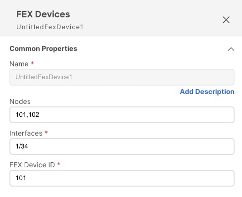
The above configuration means that there are two FEX devices, one connected to leaf switch
101and another connected to leaf switch102with both devices having FEX ID101. Since FEX ID is limited to the leaf switch scope, FEX devices that are connected to different leaf switches can have the same IDs. -
Provide one or more Interfaces that connect to the FEX device.
-
Provide the FEX Device ID.
-
Repeat this step to create any additional FEX Device policies.
-
-
Click Save to save the changes you’ve made to the template.
When you save (or deploy) the template to one or more sites, the Orchestrator will verify that the specified nodes or interfaces are valid for the sites and will return an error if that is not the case.
-
Click Deploy to deploy the template to the associated sites.
The process for deploying tenant policy templates is identical to how you deploy application templates.
If you have previously deployed this template but made no changes to it since, the Deploy summary indicates that there are no changes, and you can choose to redeploy the entire template. In this case, you can skip this step.
Otherwise, the Deploy to sites window shows you a summary of the configuration differences that will be deployed to sites. In this case only the difference in configuration is deployed to the sites. If you want to redeploy the entire template, you must deploy when to sync the differences, and then redeploy again to push the entire configuration as described in the previous paragraph.
Creating Monitoring Policies
This section describes how to create one or more SPAN session policies using the Monitoring Policy templates.
-
Log in to your Cisco Nexus Dashboard and open the Cisco Nexus Dashboard Orchestrator service.
-
Create a new Tenant Policy.
-
From the left navigation pane, choose Configure > Policy Templates.
-
On the Monitoring Policy Templates tab, click Create Monitoring Policy Template.
-
Select the SPAN session type for this template.
You can choose one of the following:
-
Tenant - this type of SPAN sessions are referred to as ERSPAN sessions and allows you to configure an EPG belonging to the specified Tenant anywhere in the fabric as the SPAN session
sourceand another EPG belonging to the same or to a different tenant as thedestination. -
Access - allows you to configure one of the following two scenarios:
-
Access ports, port-channels, and vPC as source and destination as physical/port-channel interface, in which case the
sourceanddestinationinterfaces must be on the same switch. -
Access ports, port-channels, and vPC as source and destination as EPG, in which case it is an ERSPAN session allowing the SPAN destination to be connected anywhere in the fabric.
-
-
-
If you chose
Tenantas the session type, choose a Tenant with which to associate the monitoring policy. -
Choose the Site with which to associate the monitoring policy.
You can associate only one site to the monitoring template. Only the on-premises ACI sites support tenant policy templates and will be available for assignment.
-
In the Monitoring Policy page’s right properties sidebar, provide the Name for the template.
By default, the new template is empty, so you must add one or more fabric policies as described in the following steps.
-
Click Ok to save.
-
-
Create a SPAN Session policy for a
Tenanttype template.If you picked
Accessfor the template type, use the next step instead.-
From the +Create Object drop-down, select SPAN Session.
-
In the right properties sidebar, provide the Name for the policy.
-
(Optional) Click Add Description and provide a description for the policy.
-
Enable the Admin State check box.
If admin state is set to
disabled, no data is sent to the configured monitor. -
Click +Add Source and provide the SPAN source information.
For the source information, provide the following:
-
Name
-
Direction - the SPAN source packet direction, which can be one of the following:
-
Both- Replicate and forward packets that are incoming to the source and outgoing from the source. -
Incoming- Replicate and forward packets that are incoming to the source. -
Outgoing- Replicate and forward packets that are outgoing from the source.
-
-
Source EPG - The source of the SPAN traffic.
For
Tenanttype templates, the source is always an EPG.
Click OK to save the source. You can then click +Add Source to provide extra sources if necessary.
-
-
From the Destination Group section, provide the Tenant, Destination EPG, and Destination IP Address to which the replicated packets will be forwarded.
IPv4 and IPv6 IP addresses are supported in this field. However, you must not mix IPv4 for the Destination IP and IPv6 for the Source IP Prefix or conversely.
-
Provide the Source IP Prefix.
If a specific IP address is configured, all ERSPAN traffic will be sourced from that IP (for example, for all the ACI leaf switches sourcing the ERSPAN traffic). If instead a prefix is configured, each ACI leaf switch will be assigned a unique IP that is part of that prefix to source ERSPAN traffic. This could be useful on the destination switch to distinguish the origin of the ERSPAN traffic.
-
Choose the SPAN Version.
-
(Optional) If necessary, configure the Advanced Settings.
-
Enforce SPAN Version - When enabled, enforces the chosen SPAN Version.
If
Enabled, the SPAN session uses the specified SPAN version if the hardware supports it. Otherwise, the session will fail.If
Disabledand Version 2 is specified but is not supported by the hardware, then Version 1 is used. -
Flow ID - The identifier of the ERSPAN packet.
When packets are copied and sent through ERSPAN, the packets are encapsulated with ERSPAN header. The flow ID is the number in the ERSPAN header to identify by which ERSPAN session these packets were copied.
The range is from 1 to 1023. The default is 1.
-
TTL - The Time to Live (TTL) or hop limit in the
1-255hops range; if set to zero, then no TTL is specified. The default is 64 hops. -
DSCP - DSCP value set in the IP header of the ERSPAN packet.
-
MTU - The maximum transmission unit of the ERSPAN-generated packets.
The range is from 64 to 9216. The default is
1518.For ERSPAN, the real MTU received by the destination device will be larger than the configured MTU because the ERSPAN encapsulation is added. For ERSPAN version 2, an extra 46 bytes are added. For ERSPAN version 1, an extra 34 bytes are added. As a result, with the default MTU of 1518, the end device would actually need to support 1564 (1518 + 36) for version 2 or 1552 (1518 + 34) for version 1.
If the captured frame is larger than the configured MTU, then the frame is truncated to the MTU length when the frame is replicated. The packet/frame payload would be incomplete, but the headers should still be intact for analysis.
-
-
Repeat this step to create any additional Tenant SPAN Session policies.
-
-
Create a SPAN Session policy for an
Accesstype template.If you picked
Tenantfor the template type, use the previous step instead.-
From the +Create Object drop-down, select SPAN Session.
-
In the right properties sidebar, provide the Name for the policy.
-
(Optional) Click Add Description and provide a description for the policy.
-
Enable the Admin State checkbox.
If admin state is set to
disabled, no data is sent to the configured monitor. -
Click +Create Source and provide the SPAN source information.
For the source information, provide the following:
-
Name
-
Click +Create Access Path to add one or more paths on the leaf switch. The following paths are supported:
-
Port -
Port Channel -
Virtual Port Channel -
VPC Component PC
You can use theVPC Component PCoption if you want to configure a vPC as a source and a physical/port-channel interface as destination. Since for this use case all the interfaces must be on the same switch, you must not choose the vPC as a source and must select theVPC Component PCoption representing the interfaces of that vPC on the same switch where the destination is connected. In other words, you need to create a second SPAN session for the second switch that is part of the vPC domain so that the traffic can be spanned for the source interfaces which are part of the vPC on that switch towards a local destination.
-
-
Direction - the SPAN source packet direction, which can be one of the following:
-
Both- Replicate and forward packets that are incoming to the source and outgoing from the source. -
Incoming- Replicate and forward packets that are incoming to the source. -
Outgoing- Replicate and forward packets that are outgoing from the source.
-
-
Click +Create Filter to provide SPAN traffic filtering information.
Traffic filtering is optional and if no filters are specified then all traffic will be spanned.
You can enable filtering based on the following attributes:
-
Src IP Prefix
-
Src Port From
-
Src Port To
-
Dst IP Prefix
-
Dst Port From
-
Dst Port To
-
IP Protocol
-
SPAN Drop Packets - Allows SPAN to capture some of dropped packets that are not captured by the regular SPAN, but its limited to packets dropped as "forward drops".
If
Enabled, allows for spanning of only dropped packets and not any traffic that was not dropped.If
Disabled, SPAN captures only the traffic that was not dropped.The default value is
Disabled. -
Filter - If SPAN Drop Packets is disabled, you can filter the source packets based on the EPGs or L3Out they are coming from. To enable the filter, choose either the EPG tab or the L3Out tab, and select the Tenant. Based on your selection specific EPG from the Source EPG drop-down or specific L3Out and VLAN ID from the drop-down list.
Only those VLAN IDs are listed in the drop-down that is associated the interface in the L3Out, matching the interface as Source Path in the SPAN.
The traffic sent and received on the previously configured source interfaces will be spanned only if it belongs to the specified EPG or the L3Out node.
-
Click OK to save the source. You can then click +Add Source to provide extra sources if necessary.
-
-
Choose the Destination Type.
The replicated packets can be forwarded to either an EPG or a specific access interface. In the first case, an ERSPAN session is created to send the spanned traffic to a destination connected anywhere in the fabric; in the second case, the destination must be connected to physical/port-channel interfaces on the same switch as the source interfaces.
-
If you chose
EPGfor the Destination Type, provide the following information:-
Tenant, Destination EPG, and Destination IP Address to which the replicated packets will be forwarded.
IPv4 or IPv6 IP addresses are supported in this field. However, you must not mix IPv4 for the Destination IP and IPv6 for the Source IP Prefix or conversely.
-
Source IP Prefix - the base IP address of the IP subnet of the source packets.
-
SPAN Version
-
(Optional) Advanced Settings
-
Enforce SPAN Version - When enabled, enforces the chosen SPAN Version.
If
Enabled, the SPAN session will use the specified SPAN version if the hardware supports it. Otherwise, the session fails.If
Disabledand Version 2 is specified but is not supported by the hardware, then Version 1 is used. -
Flow ID - The identifier of the ERSPAN packet.
When packets are copied and sent through ERSPAN, the packets are encapsulated with ERSPAN header. The flow ID is the number in the ERSPAN header to identify by which ERSPAN session these packets were copied.
The range is 1-1023. The default is 1.
-
TTL - The Time to Live (TTL) or hop limit in the
1-255hops range; if set to zero, then no TTL is specified. The default is 64 hops. -
DSCP - DSCP value set in the IP header of the ERSPAN packet.
-
MTU - The MTU of the ERSPAN-generated packets.
The range is 64-9216. The default is
1518.For ERSPAN, the real MTU received by the destination device will be larger than the configured MTU because the ERSPAN encapsulation is added. For ERSPAN version 2, an extra 46 bytes are added. For ERSPAN version 1, an extra 34 bytes are added. As a result, with the default MTU of 1518, the end device would actually need to support 1564 (1518 + 36) for version 2 or 1552 (1518 + 34) for version 1.
If the captured frame is larger than the configured MTU, then the frame is truncated to the MTU length when the frame is replicated. The packet/frame payload would be incomplete, but the headers should still be intact for analysis.
-
-
-
Otherwise, if you chose
Access Interfacefor the Destination Type, provide the following information instead:-
Path Type - type of the interface, can be
PortorPort Channel. -
For
Portinterfaces, select the Node and Path. -
For
Port Channelinterfaces, select the name of the port channel. -
MTU - The MTU of the ERSPAN-generated packets.
The range is 64-9216. The default is
1518.For ERSPAN, the real MTU received by the destination device will be larger than the configured MTU because the ERSPAN encapsulation is added. For ERSPAN version 2, an extra 46 bytes are added. For ERSPAN version 1, an extra 34 bytes are added. As a result, with the default MTU of 1518, the end device would actually need to support 1564 (1518 + 36) for version 2 or 1552 (1518 + 34) for version 1.
If the captured frame is larger than the configured MTU, then the frame is truncated to the MTU length when the frame is replicated. The packet/frame payload would be incomplete, but the headers should still be intact for analysis.
-
-
Repeat this step to create any additional Access SPAN Session policies.
-
-
Click Save to save the changes you’ve made to the template.
-
Click Deploy to deploy the template to the associated sites.
The process for deploying tenant policy templates is identical to how you deploy application templates.
If you have previously deployed this template but made no changes to it since, the Deploy summary indicates that there are no changes, and you can choose to redeploy the entire template. In this case, you can skip this step.
Otherwise, the Deploy to sites window shows you a summary of the configuration differences that will be deployed to sites. Note that in this case only the difference in configuration is deployed to the sites. If you want to redeploy the entire template, you must deploy when to sync the differences, and then redeploy again to push the entire configuration as described in the previous paragraph.
First Published: 2024-03-01
Last Modified: 2024-03-01
Americas Headquarters
Cisco Systems, Inc.
170 West Tasman Drive
San Jose, CA 95134-1706
USA
http://www.cisco.com
Tel: 408 526-4000
800 553-NETS (6387)
Fax: 408 527-0883