New and Changed Information

The following table provides an overview of the significant changes up to this current release. The table does not provide an exhaustive list of all changes or of the new features up to this release.

Cisco ACI CNI plug-in Release Version

Feature

6.0(4)

Cisco Application Centric Infrastructure (ACI) supports Red Hat Agent-based OpenShift on a bare metal server.

Agent-based Openshift 4.14 on Bare Metal

This document pertains to installing OCP with the ACI CNI. However, to identify and resolve issues in your infrastructure not related to the ACI CNI, see the relevant installation guide to first install OCP on your bare metal nodes using the default OVN Kubernetes. You can check the OpenShift 4.14 container platform documentation.


Note


This document can not be used standalone. This document should be used along with the Red Hat OpenShift 4.14 Installing an on-premise cluster with the agent-based installer document to perform the OpenShift cluster installation.


Requirements for supporting OpenShift 4.14 on a Bare Metal Server

At least two network interfaces are required for bare metal nodes, one for the node network, and the second for the pod network. The design separates OpenShift node traffic from the pod traffic. There are two options available to achieve separation, resulting in control and compute machines each having two network interfaces:

  • Separate physical interface for node and infra networks

  • Single Sub interface for both node and infra networks

Separate physical interface for node and infra networks

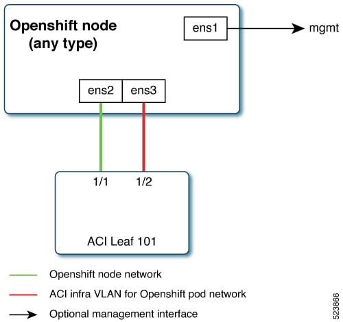
The first interface is used for the node network and the second one is used for the pod network. The second interface also carries Cisco ACI control plane traffic. A VLAN tagged subinterface can be configured on the second interface to carry the cluster's pod traffic and also the Cisco ACI control plane traffic.

Single Sub interface for both node and infra networks

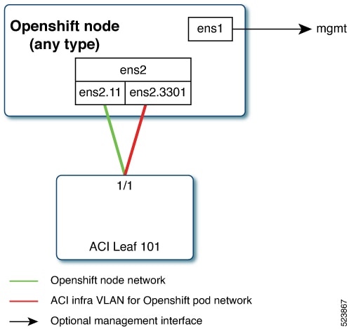
The node network and pod network are configured as VLAN subinterface of either bond0 or physical NIC. You can configure the server with additional VLAN(s) for management purpose or use the node network for management network. The design might be dependent on the server provisioning method (PXE or manual ISO boot).

Installation Process

The following sections detail the steps required to install the OpenShift cluster using the ACI CNI.

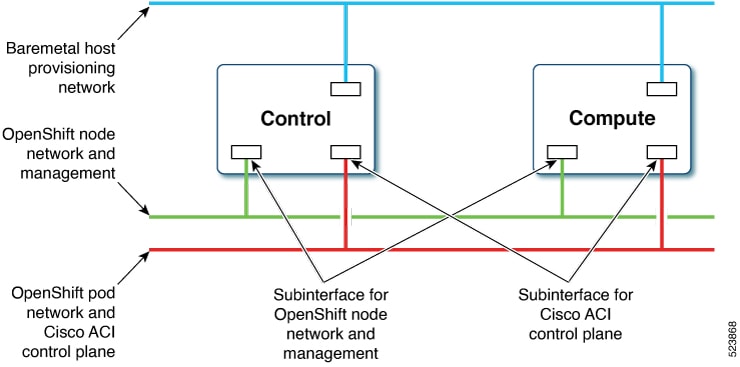
The image below illustrates the various types of networks utilized in the installation process.

At least two network interfaces are necessary for bare metal nodes: one for the node network and the other for the pod network. This design segregates OpenShift node traffic from pod traffic. A third interface is configured for the private network, essential for provisioning bare metal hosts.

Configuring the OpenShift Installer

Use this procedure to configure the OpenShift installer. The installation will use a 3 node-cluster (control will have scheduling enabled). For scaling nodes post installation, see the section, Scaling Agent-Based Installation with the Bare Metal Operator.

Before you begin

Download the OpenShift installer and OC client.

For details of the location from where you can download the installer , see the OpenShift 4.14 document titled, Installing an on-premise cluster with the Agent-based Installer.

Procedure


Step 1

Create the install-config.yaml file.


 apiVersion: v1
 baseDomain: noiro.local 
 proxy:
   httpsProxy: <http-proxy> 
   httpProxy: <https-proxy> 
   noProxy: <no-proxy>
 compute:
 - name: worker
   replicas: 0
 controlPlane:
   name: master
   replicas: 3 
 metadata:
   name: ocpbm1
 networking:
   machineNetwork:
   - cidr: 192.168.1.0/24
   clusterNetwork:
   - cidr: 10.2.0.0/16
     hostPrefix: 23
   networkType: CiscoACI
   serviceNetwork:
   - 172.30.0.0/16
 platform:
   baremetal:
     apiVIPs:
     - 192.168.1.30
     ingressVIPs:
     - 192.168.1.29
 fips: false
pullSecret: <RH-account-pull-secret> 
sshKey: <host-ssh-key>

Step 2

Create the agent-config.yaml file.


apiVersion: v1alpha1
kind: AgentConfig
metadata:
  name: ocpbm1
rendezvousIP: 192.168.1.3
AdditionalNTPSources:
  - time.cisco.com
hosts:
  - hostname: ocpbm1-master1
    role: master
    interfaces:
    - name: ens160
      macAddress: 00:50:56:97:16:db
    networkConfig:
      interfaces:
        - name: ens160
          mtu: 9000
          ipv4:
            enabled: false
          ipv6:
            enabled: false
        - name: node
          type: vlan
          mtu: 9000
          state: up
          vlan:
            base-iface: ens160
            id: 11
          ipv4:
            enabled: true
            address:
              - ip: 192.168.1.3
                prefix-length: 24
            dhcp: false
          ipv6:
            enabled: false
        - name: infra
          type: vlan
          mtu: 9000
          state: up
          vlan:
            base-iface: ens160
            id: 3301
          ipv4:
            enabled: true
            dhcp: true
          ipv6:
            enabled: false
      dns-resolver:
        config:
          server:
            - 192.168.1.2
      routes:
        config:
          - destination: 0.0.0.0/0
            next-hop-address: 192.168.1.1
            next-hop-interface: node
          - destination: 224.0.0.0/4
            next-hop-interface: infra
  - hostname: ocpbm1-master2
    role: master
    interfaces:
    - name: ens160
      macAddress: 00:50:56:97:63:de
    networkConfig:
      interfaces:
        - name: ens160
          mtu: 9000
          ipv4:
            enabled: false
          ipv6:
            enabled: false
        - name: node
          type: vlan
          mtu: 9000
          state: up
          vlan:
            base-iface: ens160
            id: 11
          ipv4:
            enabled: true
            address:
              - ip: 192.168.1.4
                prefix-length: 24
            dhcp: false
          ipv6:
            enabled: false
        - name: infra
          type: vlan
          mtu: 9000
          state: up
          vlan:
            base-iface: ens160
            id: 3301
          ipv4:
            enabled: true
            dhcp: true
          ipv6:
            enabled: false
      dns-resolver:
        config:
          server:
            - 192.168.1.2
      routes:
        config:
          - destination: 0.0.0.0/0
            next-hop-address: 192.168.1.1
            next-hop-interface: node
          - destination: 224.0.0.0/4
            next-hop-interface: infra
  - hostname: ocpbm1-master3
    role: master
    interfaces:
    - name: ens160
      macAddress: 00:50:56:97:00:e5
    networkConfig:
      interfaces:
        - name: ens160
          mtu: 9000
          ipv4:
            enabled: false
          ipv6:
            enabled: false
        - name: node
          type: vlan
          mtu: 9000
          state: up
          vlan:
            base-iface: ens160
            id: 11
          ipv4:
            enabled: true
            address:
              - ip: 192.168.1.5
                prefix-length: 24
            dhcp: false
          ipv6:
            enabled: false
        - name: infra
          type: vlan
          mtu: 9000
          state: up
          vlan:
            base-iface: ens160
            id: 3301
          ipv4:
            enabled: true
            dhcp: true
          ipv6:
            enabled: false
      dns-resolver:
        config:
          server:
            - 192.168.1.2
      routes:
        config:
          - destination: 0.0.0.0/0
            next-hop-address: 192.168.1.1
            next-hop-interface: node
          - destination: 224.0.0.0/4
            next-hop-interface: infra

Configuring ACI Infra and CNI

Use this procedure for configuring ACI infra and CNI using acc-provision.

Procedure


Sample ACI configuration:


# Configuration for ACI Fabric
#
aci_config:
  system_id: openupi                    # Every opflex cluster on the same fabric must have a distict ID
  apic_hosts:                           # List of APIC hosts to connect to for APIC API access
    - <APIC-IP>
  apic_login:
    username: <username>
    password: <password>
  vmm_domain:                     # Kubernetes VMM domain configuration
    encap_type: vxlan             # Encap mode: vxlan or vlan
    mcast_range:                  # Every vxlan VMM on the same fabric must use a distinct range
        start: 225.115.1.1
        end: 225.115.255.255
  # The following resources must already exist on the APIC,
  # this is a reference to use them
  aep: <AAEP_NAME>            # The attachment profile for ports/VPCs connected to this cluster
  vrf:                         # VRF used to create all subnets used by this Kubernetes cluster
    name: <VRF_NAME>           # This should exist, the provisioning tool does not create it
    tenant: <TENANT_WITH_VRF_DEFINITION>            # This can be tenant for this cluster (system-id) or common
  l3out:                       # L3out to use for this kubernetes cluster (in the VRF above)
    name:<L3OUT_NAME>        # This is used to provision external service IPs/LB
    external_networks:
        <EXTERNAL_EPG_NAME>    # This should also exist, the provisioning tool does not create it
agent based installer:
  enable: true
# Networks used by Kubernetes
#
net_config:
  node_subnet: 192.168.1.1/24         # Subnet to use for nodes
  pod_subnet: 10.2.0.1/16           # Subnet to use for Kubernetes Pods
  extern_dynamic: 10.3.0.1/16       # Subnet to use for dynamically allocated external services
  extern_static: 10.4.0.1/16        # Subnet to use for statically allocated external services
  node_svc_subnet: 10.5.0.1/16      # Subnet to use for service graph
  kubeapi_vlan: 11                  # The VLAN used by the internal physdom for nodes
  service_vlan: 21                  # The VLAN used for external LoadBalancer services
  infra_vlan: 3301

Note

 
The *.apps.<cluster_name>.<base_domain> records in the user-provisioned DNS should refer to the same IP address used in the ingressVIPs in the install-config.yaml file.

Customize the sample acc-provision input file shown above as per your requirements. Then install the latest acc-provision package from here, and run pip install acc-provision. Run the acc-provision as follows:


$ ~/openupi$ pwd
/home/<user>/openupi

$ ~/openupi$ acc-provision -a -c acc_provision_input.yaml -f openshift-4.14-agent-based-baremetal -u <user> -p <password> -o aci_deployment.yaml -z aci deployment.yaml.tar.gz

This generates a new aci_deployment.yaml.tar.gz file which contains the ACI CNI manifests, and is used later during the OpenShift installation.


Preparing Custom Network Configuration for OpenShift Nodes

ACI CNI requires additional VLANs to be extended towards each OpenShift node. Additional VLANS are required for all master and worker nodes.

You can configure additional VLANs on the interface that will be configured with the node network subnet or can be configured on an additional physical interface on the hosts.

The available option to configure a network interface of a host is to provide the configuration in agent-config.yaml in NMState format. For details about creating agent-config.yaml , see the Configuring the OpenShift Installer section.

Modifying the agent-config file

Use this procedure to modify the agent-config.yaml file.

Before you begin

The agent-config file, with additional NIC configuration, needs to extend the Cisco ACI internal network (Infra VLAN) up to the server level. This interface is used to carry VxLAN traffic from OVS towards the ACI leaf switch with an appropriate tag for the pod network. To achieve the separation between the OpenShift node traffic and pod traffic, use the Single Sub interface for both node and infra networks approach. The relevant details have been discussed in the Requirements section.

The following YAML snippet outlines an AgentConfig. It includes essential details like rendezvous IP, host configurations, and network interface settings for streamlined deployment.


apiVersion: v1alpha1
kind: AgentConfig
metadata:
  name: ocpbm1
rendezvousIP: 192.168.1.3. -> A
AdditionalNTPSources:
  - time.cisco.com
hosts: -> B
  - hostname: ocpbm1-master1 -> C
    role: master
    interfaces:
    - name: ens160
      macAddress: 00:50:56:97:16:db
    networkConfig: -> D
      interfaces:
        - name: ens160
          mtu: 9000
          ipv4:
            enabled: false
          ipv6:
            enabled: false
        - name: node
          type: vlan
          mtu: 9000
          state: up
          vlan:
            base-iface: ens160
            id: 11
          ipv4:
            enabled: true
            address:
              - ip: 192.168.1.3
                prefix-length: 24
            dhcp: false
          ipv6:
            enabled: false
        - name: infra
          type: vlan
          mtu: 9000
          state: up
          vlan:
            base-iface: ens160
            id: 3301
          ipv4:
            enabled: true
            dhcp: true
          ipv6:
            enabled: false
      dns-resolver:
        config:
          server:
            - 192.168.1.2
      routes:
        config:
          - destination: 0.0.0.0/0
            next-hop-address: 192.168.1.1
            next-hop-interface: node
          - destination: 224.0.0.0/4
            next-hop-interface: infra
  

In the above sample, sections have been marked as A, B, C, D. Here are the details for better understanding.

  • A: This IP address is used to determine which node performs the bootstrapping process as well as running the assisted-service component. You must provide the rendezvous IP address when you do not specify at least one host’s IP address in the networkConfig parameter. If this address is not provided, one IP address is selected from the provided hosts' networkConfig.

  • B: Host configuration. The number of hosts defined must not exceed the total number of hosts defined in the install-config.yaml file, which is the sum of the values of the compute.replicas and controlPlane.replicas parameters.

  • C: Overrides the hostname obtained from either the Dynamic Host Configuration Protocol (DHCP) or a reverse DNS lookup. Each host must have a unique hostname supplied by one of these methods.

  • D: Configures the network interface of a host in NMState format.

Procedure


Step 1

Create a root folder for your cluster.


cd /home/<user>/openupi 
mkdir upi

Step 2

Copy the install-config.yaml, agent-config.yaml in the newly created upi folder.

Step 3

Create the openshift directory.

mkdir -p /home/<user>/openupi/upi/openshift

Step 4

Extract all the ACI manifest files in upi/openshift/.

tar -xvf aci_deployment.yaml.tar.gz -C upi/openshift/

Step 5

Create the iso image.

openshift-install agent create image --dir=upi --log-level debug 

Step 6

Boot the agent.x86_64.iso image on the bare metal machines.

The agent.x86_64.iso is now ready and can be copied to your HTTP server, so they can be served to your nodes. The agent.x86_64.iso file will be consumed by every node and the network configuration for each node will be recognized based on the mac-address mentioned in the NMState configuration for each node.


Updating the Default Ingress Controller

For updating the default Ingress Controller publish strategy to use the ACI Loadbalancer, log in as a user with cluster-admin privileges and run the following:


oc replace --force --wait --filename - <<EOF 
apiVersion: operator.openshift.io/v1 kind: 
IngressController metadata:
  namespace: openshift-ingress-operator 
name: default spec:
 endpointPublishingStrategy: 
   type: LoadBalancerService 
   loadBalancer:
     scope: External 
EOF

For more details, see the Configuring the Default Ingress Controller for your Cluster to be Internal section in the Ingress Operator in OpenShift Container Platform Red Hat guide.

Scaling Agent-based Installation with Bare Metal Operator

Use this procedure to add workers or scale nodes in a cluster.

Procedure


Step 1

Power off the bare metal node by using the baseboard management controller (BMC), and ensure it is off.

Step 2

Apply configuration file for the bare metal node, use one of the following example bmh.yaml files, replacing values in the YAML to match your environment:


apiVersion: metal3.io/v1alpha1
kind: Provisioning
metadata:
  finalizers:
  - provisioning.metal3.io
  name: provisioning-configuration
spec:
  preProvisioningOSDownloadURLs: {}
  provisioningMacAddresses:
  - <control-node01 mac address>
  - <control-node02 mac address>
  - <control-node03 mac address>
  provisioningNetwork: Managed
  provisioningIP: 192.168.254.30
  provisioningNetworkCIDR: 192.168.254.0/24
  provisioningDHCPRange: 192.168.254.3,192.168.254.10
  provisioningInterface: ens70s0f1
---
apiVersion: v1
kind: Secret
metadata:
  name: bmc-credentials
  namespace: openshift-machine-api
data:
  username: <base64_of_uid>
  password: <base64_of_pwd>
---
apiVersion: v1
kind: Secret
metadata:
 name: bm-compute-0-netconfig
 namespace: openshift-machine-api
type: Opaque
stringData:
 nmstate: |
  interfaces:
    - name: ens160
      mtu: 9000
      ipv4:
        enabled: false
      ipv6:
        enabled: false
    - name: node
      type: vlan
      mtu: 9000
      state: up
      vlan:
        base-iface: ens160
        id: 11
      ipv4:
        enabled: true
        address:
          - ip: 192.168.1.6
            prefix-length: 24
        dhcp: false
      ipv6:
        enabled: false
    - name: infra
      type: vlan
      mtu: 9000
      state: up
      vlan:
        base-iface: ens160
        id: 3301
      ipv4:
        enabled: true
        dhcp: true
      ipv6:
        enabled: false
  dns-resolver:
    config:
      server:
        - 192.168.1.2
  routes:
    config:
      - destination: 0.0.0.0/0
        next-hop-address: 192.168.1.1
        next-hop-interface: node
      - destination: 224.0.0.0/4
        next-hop-interface: infra
---
apiVersion: metal3.io/v1alpha1
kind: BareMetalHost
metadata:
  name: compute-0
  namespace: openshift-machine-api
spec:
  automatedCleaningMode: metadata
  online: true
  bootMACAddress: <nic1_mac_address>
  bmc:
    address: <protocol>://<bmc_url>
    credentialsName: bmc-credentials
    disableCertificateVerification: True
  preprovisioningNetworkDataName: bm-compute-0-netconfig

Note


To enable multiple worker nodes, you must generate distinct netconfig secrets for each node. Additionally, it's crucial to note that deleting a BaremetalHost object will also remove the associated secrets. Therefore, when utilizing multiple BaremetalHost objects, ensure that the credential secret is retained for the non-deleted BaremetalHost instances to maintain proper functionality

Step 3

Check the respective objects created (the required command has been indicated for each object):

  • Provisioning Network: Private network used for PXE booting.

    . oc describe provisioning provisioning-configuration
  • Secret bmc-credentials: Credentials for the bmc access.

     . oc describe secret - n openshift-machine-api bmc-credentials 
  • Secret bm-compute-0-netconfig: Custom Network configuration for worker node.

    . oc describe secret - n openshift-machine-api bm-compute-0-netconfig
  • BareMetalHost compute-0: Configuration to manage the baremetal node.

     . oc describe baremetalhost compute-0 -n openshift-machine-api

Step 4

Scale up the number of replicas to match the number of available bare metal hosts:

oc scale machineset -n openshift-machine-api <worker-machineset> --replicas=1

What to do next

Proceed with the tracking and verifying installation progress of the cluster; see the Redhat OpenShift 4.14 document (mentioned earlier in the chapter).