New and Changed Information
The following table provides an overview of the significant changes to the organization and features in this guide from the release the guide was first published to the current release. The table does not provide an exhaustive list of all changes made to the guide.
|
Release |
New Feature or Update |
Where Documented |
|---|---|---|
|
4.2(2e) |
First release of this document. |
-- |
Summary
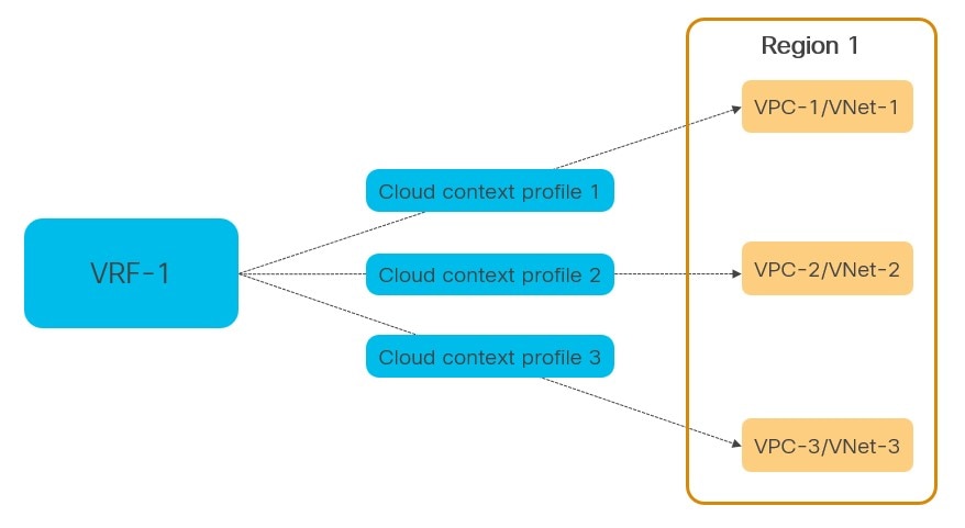
The definition of a specific object on Cisco Cloud Network Controller (CCNC), named Cloud Context Profile (cloudCtxProfile), allows you to deploy a Virtual Private Cloud (VPC) on AWS Cloud that is also known as Virtual Network (VNet) on Azure Cloud.
Before CCNC release 26.0(2), the creation of a Cloud Context Profile was done automatically, because of the association between a VRF instance and a specific Cloud region. This had two main implications:
-
The name of the
cloudCtxProfileobject was hardcoded asVRFName-RegionName. -
It was only possible to deploy a single VPC (or VNet) mapped to a VRF instance in a single region.
CCNC release 26.0(2) introduces the capability of defining one or more cloud context profiles objects mapped to the same VRF instance, with the result of being able to deploy multiple VPCs (or VNet) for a given VRF instance in the same Cloud Region.
 Note |
A unique name for each tenant must now be explicitly assigned to every Cloud Context Profile defined. |
This new functionality can be configured directly on CCNC or, as discussed in this document, it is also offered on Cisco Nexus Dashboard Orchestrator (NDO) starting from release 4.2(2) for all the Multi-Cloud deployments where NDO interacts with multiple CCNC instances.
Prerequisites
Before you follow the procedures described in this document, you must complete the following basic configuration tasks:
-
Deploy and have ready a Cisco Nexus Dashboard cluster.
This is described in detail in the Cisco Nexus Dashboard Deployment Guide for your release.
-
Onboard one or more cloud sites in the Cisco Nexus Dashboard.
This is described in detail in the Cisco Nexus Dashboard User Guide for your release.
-
Install and enable Cisco Nexus Dashboard Orchestrator, Release 4.2(2) or later.
This is described in detail in the Cisco Nexus Dashboard Orchestrator Deployment Guide for your release.
-
Enable the cloud sites for management in the orchestrator service and complete the basic infra configuration.
This is described in detail in the Cisco Nexus Dashboard Orchestrator Configuration Guide for ACI Fabrics for your release.
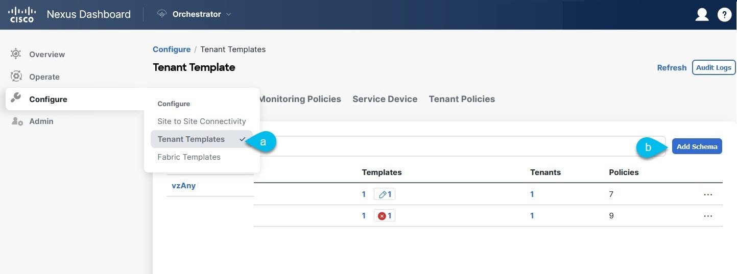
Creating Schema and Templates
Before you begin
The following guidelines apply when creating the schemas and templates using the Cisco Nexus Dashboard Orchestrator:
-
You must have a user with either
Power UserorSite Managerread/write role to create and manage tenants. -
You must have at least one available tenant that you want to incorporate into your site.
For more information, see Cisco Nexus Dashboard Orchestrator Configuration Guide for ACI Fabrics.
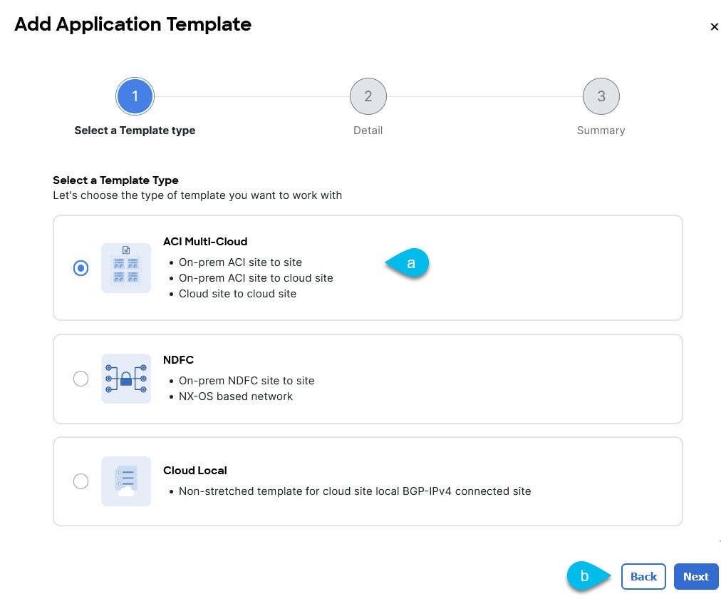
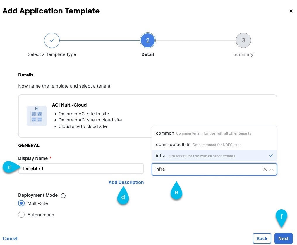
Procedure
|
Step 1 |
Log in to your Cisco Nexus Dashboard and open the Cisco Nexus Dashboard Orchestrator service. |
||
|
Step 2 |
Create a new schema:
|
||
|
Step 3 |
In the schema page, click Create New Template.
|
||
|
Step 4 |
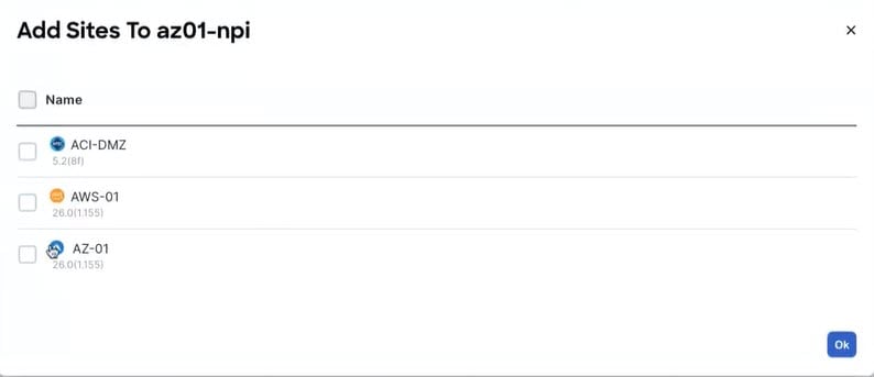
The next step is to assign the template to sites. Deploy fabric configuration by deploying one template at a time to one or more sites. You must associate the template with at least one site where you want to deploy the configuration.
|
Configuring multiple VPCs/VNets in the same VRF Instance
Before you begin
You must have the schema and template that is created and a tenant that is assigned to the template, as described in Creating Schema and Templates.
This section describes how to create a VRF instance, associate the VRF instance to a specific Cloud region and then define multiple VPC/VNets mapped to that VRF instance.
Procedure
|
Step 1 |
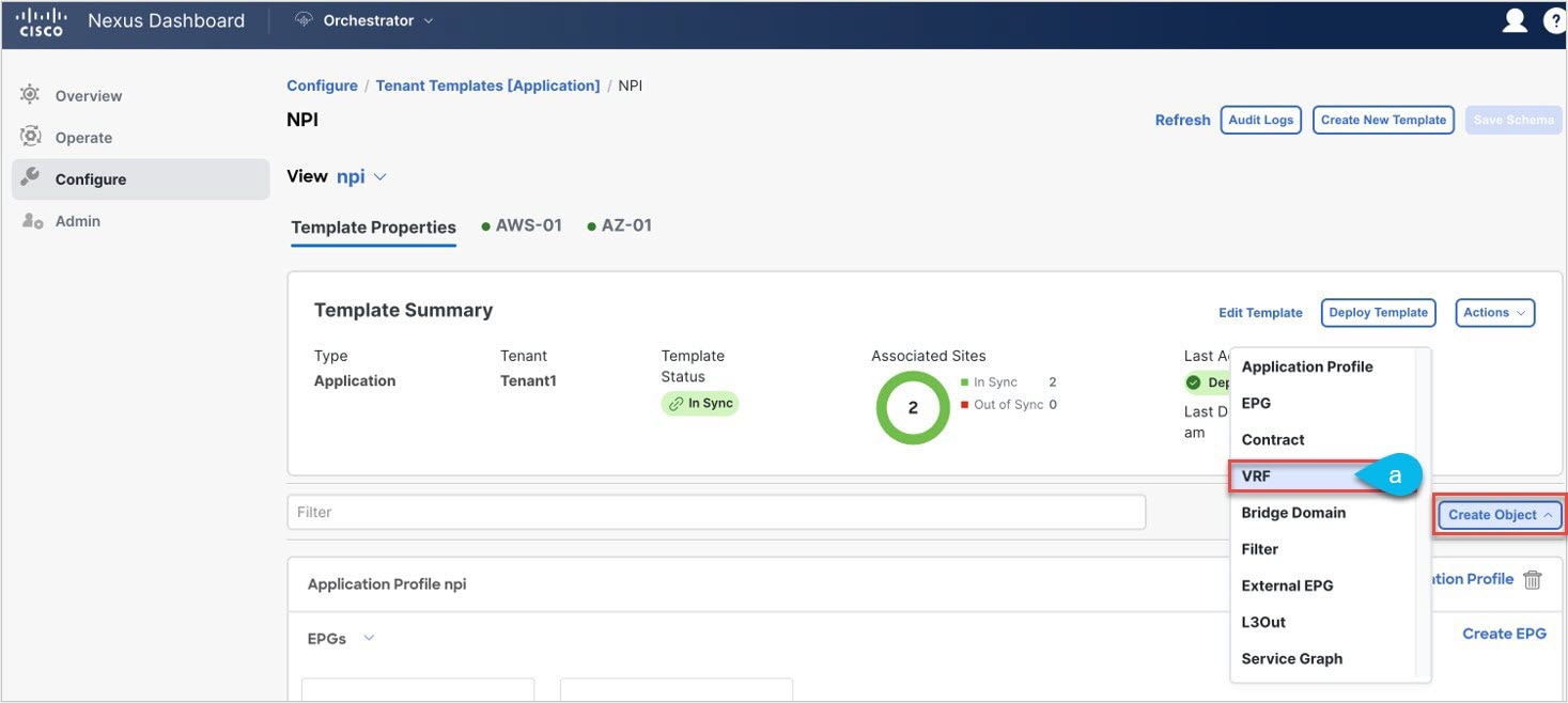
Choose the schema and template where you want to create the VRF instance. |
||
|
Step 2 |
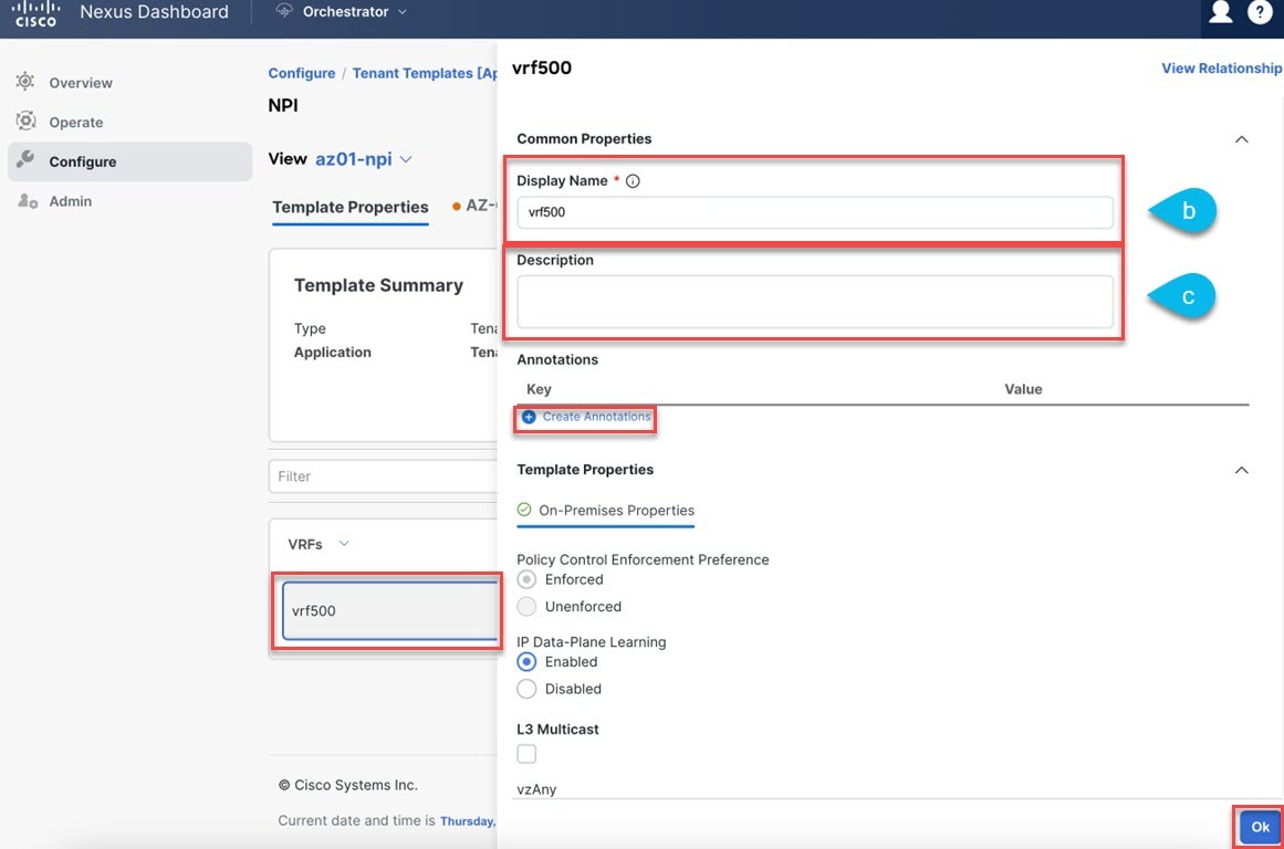
Create the VRF instance.
|
||
|
Step 3 |
(Optional) Add one or more Annotations. This allows you to add arbitrary |
||
|
Step 4 |
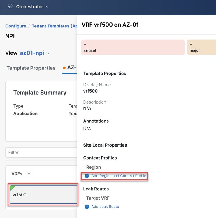
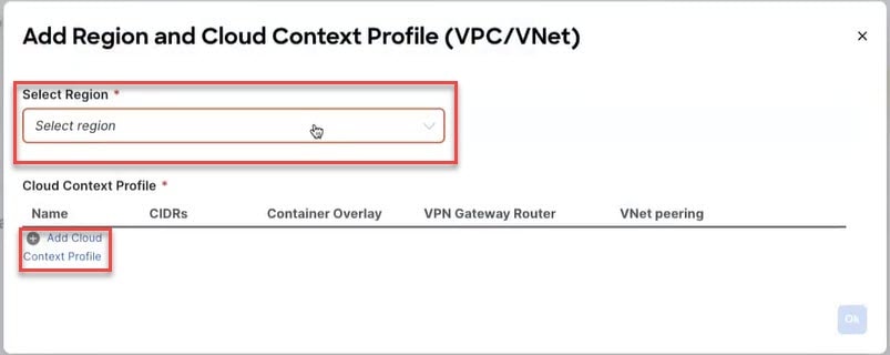
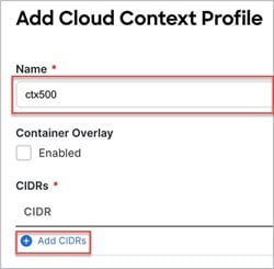
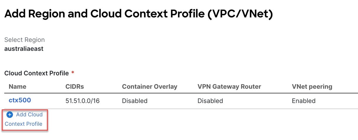
Select the site local template for the Azure/AWS site choose the VRF instance from the list of objects.
|
||
|
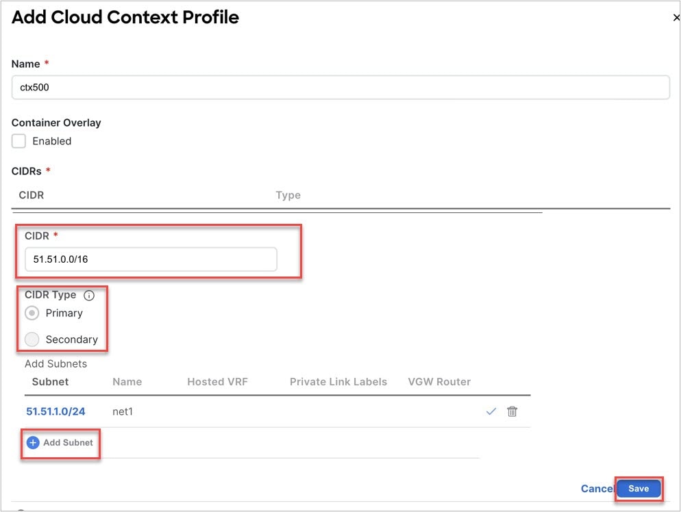
Step 5 |
Click Ok to finish adding the cloud context profile to the VRF instance. 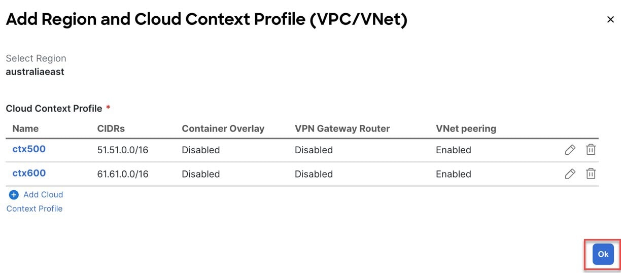 |
||
|
Step 6 |
Click on the Deploy Template button at the top-right corner of the screen to deploy the schema to the sites. 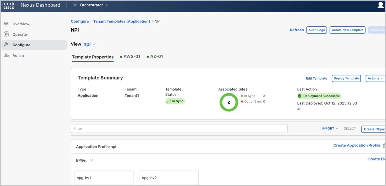
|
What to do next
You should see a message saying Deployment Sucessful at this point.
 Feedback