New and Changed Information
The following table provides an overview of the significant changes up to this current release. The table does not provide an exhaustive list of all changes or of the new features up to this release.
|
Cisco APIC Release |
Feature |
|---|---|
|
6.0(2) |
Support for deploying virtual APIC using AWS. |
Overview
Beginning with Cisco APIC release 6.0(2), you can deploy a cluster wherein all the APICs in the cluster are virtual APICs. You can deploy virtual APIC(s) on an ESXi using the VMware vCenter, or you can deploy virtual APICs on a public cloud. The public cloud supported for this release is, Amazon Web Services (AWS).
This document provides details about deploying a virtual APIC using AWS; for details about deploying virtual APIC on an ESXi host using VMware vCenter, see the Deploying Virtual APIC Using VMware vCenter document.
In this deployment, the virtual APIC cluster is running on the AWS public cloud and the fabric switches are deployed on the customer premises (on-prem). The APICs are remotely connected to the fabric through a layer 3 network. A three-node cluster is recommended. To ensure high availability and redundancy, the three APICs are deployed under three different availability zones (AZ) in AWS. Each AZ requires a different subnet.
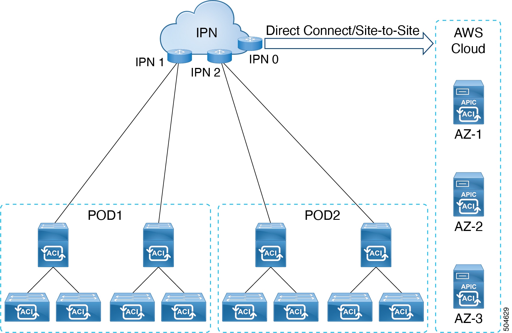
The IPN can be connected to the AWS cloud using direct connect or site-to-site VPN. Ensure to have a minimum bandwidth of 10 Gbps between the on-prem device(s) connected via the IPN and the APIC cluster on the AWS cloud .
For more information about direct connect and site-to-site VPN, refer the relevant AWS documentation.
Guidelines and Limitations
Following are the guidelines and limitations for deploying virtual APIC using AWS:
-
Fabric switches must be running Cisco APIC release 6.0(2) or later. Fabric switches running versions earlier than release 6.0(2) can be automatically upgraded to release 6.0(2) release during fabric discovery using Auto Firmware Update.
-
No support for mixed mode, that is, all the APICs of a cluster must be of the same type.
-
Virtual APIC on AWS cannot form a cluster with a virtual APIC on an ESXi host.
-
Virtual APIC on AWS cannot form a cluster with a physical APIC.
-
-
Virtual APICs deployed using ESXi cannot be migrated to AWS, and vice-versa (deployed on AWS to ESXi). Migrating from a virtual APIC deployed using AWS to a physical APIC is also not supported. For the supported migration scenario, see the Migrating from a Physical APIC to a Virtual APIC section.
-
After you have deployed a virtual APIC (with release 6.0(2)) using AWS, you cannot downgrade it to a release prior to Cisco APIC release 6.0(2).
-
No standby APIC support (no redundancy).
In the case of a physical APIC cluster, the standby APIC is automatically updated with firmware updates to ensure it is the same firmware version as the active cluster. This enables APIC replacement in the event of a failure. However, in the case of a virtual APIC cluster, the user can create an instance of the APIC with the same version as needed, so a standby APIC is not necessary.
-
Cluster and fabric security is provided using self-signed certificates.
-
IPv6 is not supported on virtual APIC deployed using AWS.
IPv6 is not supported for inband and out-of-band management with contracts.
-
No apps or app-infra supported on a virtual APIC on AWS, that is, no external ACI apps can be downloaded and installed on a virtual APIC (deployed using AWS) from the DC AppCenter. Only pre-packaged apps are supported.
-
Virtual APIC cluster is supported in all Multi-Pod, Remote Leaf, and Multi-Site topologies. Refer the Verified Scalability Guide for Cisco APIC for scalability limitations.
Deploying Virtual APIC Using AWS
Use this procedure to deploy Cisco virtual APIC using AWS.
Before you begin
Prerequisites:
-
Log in to your Amazon account and verify that you have the administrator access on AWS.
-
Ensure that your AWS account has an allowed limit to deploy the instances. You can check your account instance limits in the AWS Management Console, here: Services > EC2 > Limits.
At least three EC instances are required for an APIC cluster in production, which means your AWS account needs to be able to launch three additional r6i.4xlarge EC2 instances.
The table below displays the cloud instance types supported by virtual APIC on AWS:
AWS EC2 Instance
vCPU
Memory (in GB RAM)
r6i.4xlarge (recommended)
16
128
r6i.8xlarge
32
256
-
Create network resources which will be used for stack creation. Create the following resources:
-
VPC ID—Virtual Private Cloud (VPC) ID on which the virtual APIC will be deployed. Ensure that the VPC IP prefix is not conflicting with the IP prefixes of the on-prem devices.
If you already have a VPC ID, that can be used. Creation of a new VPC is not mandatory.
-
Subnet ID—Subnet range for your VPC.
For high availability, create three subnet IDs for each availability zone; one for out-of-band management, infra and inband management. In a 3-node cluster, we have three availability zones, and nine subnet IDs are required. Keep them handy as they will be used in the deployment procedure. Clearly indicate the subnet ids for each availability zone.
AZ1
APIC 1
Subnet ids for OOB, infra, inband management.
AZ2
APIC 2
Subnet ids for OOB, infra, inband management.
AZ3
APIC 3
Subnet ids for OOB, infra, inband management.

Note
All the three subnets must belong to one availability zone for one APIC.
You can refer to the relevant AWS documentation for details about creating VPC and subnets.
Example:
Vpc : vpc-062429c055a4a7416
Subnets:
VPC: vapic-example1-vpc, AZ: AZ1
vapic-oob-az1-subnet:   10.1.0.0/28    GW: 10.1.0.1
vapic-infra-az1-subnet: 10.1.0.16/28   GW: 10.1.0.17
vapic-inb-az1-subnet:   10.1.0.128/28  GW: 10.1.0.129
See the Additional References section for an example of the cloud formation template that automates the creation pre-requisite configurations.
-
-
Create an Amazon EC2 SSH key pair:
-
Click the Services link at the top left area of the screen, then click the EC2 link.
The EC2 Dashboard screen appears.
-
In the EC2 Dashboard screen, click the Key Pairs link.
-
In the Create Key Pair screen, enter the following details:
-
Enter a unique name for this key pair; click Create.
-
A screen is displayed that shows the public key that is stored in AWS. In addition, a Privacy Enhanced Mail (PEM) file is downloaded locally to your system with the private key.
-
Move the private key PEM file to a safe location on your system and note the location.
If you already have a key pair created, that can be used. Creation of a new key pair is not mandatory.
-
-
-
Bandwidth of 10 Gbps is mandatory between the AWS cloud and the fabric (on-prem device(s)).
-
Latency tolerance is up to 50 ms.
Procedure
|
Step 1 |
Log in to your AWS MarketPlace account. Search for Cisco APIC 6.0(2h). You are directed to the Cisco APIC page which has the 6.0(2h) software details. You can see all the relevant details under the following tabs— Overview, Pricing, Usage, Support, Reviews. For Pricing details based on the instance type, click the Pricing tab. See the Prerequisites section above for the supported instance types.
|
||
|
Step 2 |
Click the Continue to Subscribe button. |
||
|
Step 3 |
Click the Continue to Configuration button. |
||
|
Step 4 |
On the Configure this software page, enter the following details: |
||
|
Step 5 |
Click the Continue to Launch button. |
||
|
Step 6 |
On the Launch this software page, for the Choose Action field, select the Launch CloudFormation option from the drop-down list. |
||
|
Step 7 |
Click Launch. |
||
|
Step 8 |
In the Create Stack screen that is displayed, enter the following details: |
||
|
Step 9 |
Click Next. |
||
|
Step 10 |
In the Specify stack details screen, enter the following details:
|
||
|
Step 11 |
Click Next. The Configure Stack Options page is displayed. |
||
|
Step 12 |
Click Next. The Review virtual APIC page is displayed. Ensure that the information displayed in the Parameters pane is accurate. |
||
|
Step 13 |
Click Submit. This initiates the stack creation. You can check the progress of stack creation in the Events tab. Check the Status column which displays the current status, CREATE_IN_PROGRESS. The stack creation takes about 8-10 minutes. After the stack is successfully created, the Status column displays the status as, CREATE_COMPLETE. |
||
|
Step 14 |
Check the Outputs tab. Note down the parameters displayed here. The OOBMgmt IP address displayed here (as seen below) is required while configuring the nodes using the APIC Cluster Bringup GUI. |
||
|
Step 15 |
On the AWS home screen, in the search box, next to Services, search for EC2. |
||
|
Step 16 |
Navigate to Resources > Instances. |
||
|
Step 17 |
Check the Status Check column for the newly created stack. Ensure that checks passed is displayed. |
||
|
Step 18 |
Repeat the steps detailed above to create each node in a cluster. For example, if you are building a 3-node cluster, perform the above procedure three times. Ensure that the admin password is the same for all the APIC nodes. Also ensure to verify that the Status Check column for each node displays checks passed for all the newly created instances (stacks) before proceeding to the APIC Cluster Bringup GUI. |
What to do next
For initial bootup and cluster bring up, see the Bringing Up the Cisco APIC Cluster Using the GUI procedure in the Cisco APIC Getting Started Guide. Use the OOB management IP address to reach the cluster bringup GUI.
Note |
To expand a virtual APIC AWS cluster, after the initial cluster bringup, you can use the Add Node option in the Cisco APIC GUI. Navigate to System > Controllers. In the Navigation pane, expand Controllers > apic_controller_name > Cluster as Seen by Node > Actions > Add Node. Cluster expansion by increasing the cluster size and commissioning the node is not supported. |
Creating an ACI Network with a Layer 3 Connected APIC Cluster
The procedures in this section establish the connectivity between the created virtual APIC cluster (on the cloud), and the remote ACI fabric. The APIC cluster on the cloud, is able to discover the fabric nodes using DHCP relay and an OSPF or BGP underlay provided by the IPN.
The following list outlines the steps to deploy an ACI network with an APIC cluster on the cloud:
Procedure
|
Step 1 |
Configure the IPN as described is these procedures —Provisioning the Fabric-Facing IPN Device and Provisioning the APIC Cluster-Facing IPN Device. |
|
Step 2 |
Bring up the APIC cluster as detailed above. See Deploying Virtual APIC Using AWS. |
|
Step 3 |
Configure a layer 3 connection for the APIC cluster to communicate over the IPN with the fabric pod. See Preparing Connectivity to the Fabric Pod. |
|
Step 4 |
Bring up the fabric pod. The fabric will be discovered by the APIC cluster over the layer 3 connection as described in Summary of Fabric Discovery and Registration. |
What to do next
You can connect additional fabric pods and remote leaf sites to the layer 3 connected APIC cluster in a similar manner.
Guidelines and Restrictions for Deploying APIC Cluster Connectivity to the Fabric Over a Layer 3 Network
When deploying a virtual layer 3-connected APIC cluster, follow these guidelines and limitations.
-
All APIC cluster sizes are supported in a layer 3 connected APIC pod.
-
APICs in a layer 3 connected APIC pod cannot form a cluster with APICs within the fabric pod. In this topology, there should be no APICs in the fabric pod.
-
The layer 3 connected APICs can be in the same subnet or in different subnets.
-
The layer 3 connected APICs can be geographically distributed from each other provided that the latency between APICs and with the fabric pod does not exceed 50 milliseconds round-trip time (RTT), which translates approximately to a geographical distance of up to 2,500 miles.
-
Although any device that can meet the IPN network requirements can be used as an IPN device, we recommend to deploy, when possible, switches of the Cisco Nexus 9300 Cloud Scale family. These are the devices most commonly found in production and also the devices more frequently validated in Cisco internal testing. For further information about IPN device requirements, see "Inter-Pod Connectivity Deployment Considerations" in the ACI Multi-Pod White Paper.
-
The APIC subnets must be advertised to the spines as either OSPF or BGP routes. An OSPF/ BGP underlay is supported.
-
As all control plane traffic between the APIC cluster and the fabric pod traverses the IPN, we recommend configuring QoS for this traffic. See the Configuring QoS section in this guide.
-
APIC Cluster Connectivity to the Fabric Over a Layer 3 Network does not support the following:
-
ACI CNI for Kubernetes (Redhat Openshift, SUSE/Rancher RKE, Upstream Kubernetes on Ubuntu)
-
ACI ML2 for Openstack (Redhat Openstack, Canonical Openstack)
-
-
Virtual APIC AWS cluster connectivity to the fabric over a layer 3 network supports permissive mode by default.
Provisioning the APIC Cluster-Facing IPN Device
This section describes the configuration of the IPN device connected to Pod 0, the APIC cluster pod. With reference to the topology in the Overview section, the cluster-facing IPN device is shown as IPN0. As a recommended practice, the IPN0 comprises two devices for redundancy. The fabric interface of each APIC is dual-homed to the two devices.
In the following configuration example, two Cisco Nexus 9000 series switches (IPN0a and IPN0b) are configured with the following choices:
-
VLAN 1500 is used as interface VLAN for the APICs.
-
The switch interfaces are configured as layer 2 trunk ports. As an alternative, the interfaces could be access ports if the APIC fabric interface is configured to use VLAN 0 during APIC setup.
-
Both switches are configured using HSRP to share a single IP address that serves as the APIC subnet default gateway address.
-
APIC subnets are advertised to the spines using OSPF as the underlay protocol. As an alternative, a BGP underlay could be deployed.
# Example configuration of IPN0a:

interface Vlan1500
  no shutdown
  vrf member IPN
  ip address 172.16.0.252/24
  ip ospf passive-interface
  ip router ospf 1 area 0.0.0.0
  hsrp version 2
  hsrp 1500
    ip 172.16.0.1

interface Ethernet1/1
  switchport mode trunk
  switchport trunk vlan 1500
  spanning-tree port type edge trunk


# Example configuration of IPN0b:

interface Vlan1500
  no shutdown
  vrf member IPN
  ip address 172.16.0.253/24
  ip ospf passive-interface
  ip router ospf 1 area 0.0.0.0
  hsrp version 2
  hsrp 1500
    ip 172.16.0.1

interface Ethernet1/1
  switchport mode trunk
  switchport trunk vlan 1500
  spanning-tree port type edge trunk
Provisioning the Fabric-Facing IPN Device
This section describes the configuration of the MPod IPN, which is the IPN device connected to a fabric pod. The IPN is not managed by the APIC. It must be preconfigured with the following information:
-
Configure the interfaces connected to the spines of the fabric pod.
-
Enable OSPF (or BGP) on the sub-interface specifying the OSPF process and area ID.
-
Enable DHCP Relay on the IPN interfaces connected to spines.
-
Enable PIM.
-
Add bridge domain GIPo range as PIM Bidirectional (bidir) group range (default is 225.0.0.0/15).
A group in bidir mode has only shared tree forwarding capabilities.
-
Add 239.255.255.240/28 as PIM bidir group range.
-
Enable PIM on the interfaces connected to all spines.
Note |
Multicast is not required for a single pod fabric with a layer 3-connected APIC cluster, but it is required between pods in a multi-pod fabric. |
Note |
When deploying PIM bidir, at any given time it is only possible to have a single active RP (Rendezvous Point) for a given multicast group range. RP redundancy is hence achieved by leveraging a Phantom RP configuration. Because multicast source information is no longer available in Bidir, the Anycast or MSDP mechanism used to provide redundancy in sparse-mode is not an option for bidir. |
The following switch configuration example is for a switch deployed as the MPod IPN. The DHCP relay configuration allows the fabric to be discovered by the APIC cluster. The deployment of a dedicated VRF in the IPN for inter-pod connectivity is optional, but is a best practice recommendation. As an alternative, you can use a global routing domain.
Example: OSPF as the underlay protocol
feature dhcp
feature pim
service dhcp
ip dhcp relay

# Create a new VRF.
vrf context overlay-1
  ip pim rp-address 12.1.1.1 group-list 225.0.0.0/15 bidir
  ip pim rp-address 12.1.1.1 group-list 239.255.255.240/28 bidir

interface Ethernet1/54.4    #spine connected interface
  mtu 9150
  encapsulation dot1q 4
  vrf member overlay-1
  ip address 192.168.0.1/30
  ip ospf network point-to-point
  ip router ospf infra area 0.0.0.0
  ip dhcp relay address 172.16.0.2  #infra address of APIC 1
  ip dhcp relay address 172.16.0.3  #infra address of APIC 2
  ip dhcp relay address 172.16.0.4  #infra address of APIC 3
  no shutdown

interface loopback29
  vrf member overlay-1
  ip address 12.1.1.2/30

router ospf infra
  vrf overlay-1
    router-id 29.29.29.29
Example: BGP as the underlay protocol
router bgp 65010
  vrf IPN
    neighbor 192.168.0.2 remote-as 65001
      address-family ipv4 unicast
        disable-peer-as-check
In the BGP configuration, the disable-peer-as-check command is needed for multi-pod because each pod uses the same ASN.
Preparing Connectivity to the Fabric Pod
Before bringing up the fabric pod (Pod 1), you first must pre-configure the layer 3-connected APIC cluster (Pod 0) for connectivity through the IPN to a spine in the fabric pod. This is necessary for automatic fabric discovery.
Before you begin
-
If the layer 3 conncted virtual APIC cluster is deployed in a separate security zone from the fabric, configure the firewall to allow any necessary protocols and ports.
-
Configure the inter-pod network (IPN) device that is connected to the fabric pod spines.
-
Configure a fabric external routing profile.
-
Configure an OSPF interface policy if you are using OSPF as the underlay protocol.
Procedure
|
Step 1 |
Log in to one of the APICs in the layer 3 connected cluster. |
|
Step 2 |
Choose . |
|
Step 3 |
In the work pane, click the + symbol. The Set Up Pod TEP Pool dialog box opens. |
|
Step 4 |
In the Set Up Pod TEP Pool dialog box, complete the following steps:
|
|
Step 5 |
In the navigation pane, expand Quick Start and click Add Pod. |
|
Step 6 |
In the work pane, click Add Pod. |
|
Step 7 |
In the Configure Interpod Connectivity STEP 1 > Overview panel, review the tasks that are required to configure interpod network (IPN) connectivity, and then click Get Started. |
|
Step 8 |
In the Configure Interpod Connectivity STEP 2 > IP Connectivity dialog box, complete the following steps: |
|
Step 9 |
In the Configure Interpod Connectivity STEP 3 > Routing Protocols dialog box, in the OSPF area, complete the following steps to configure OSPF for the spine to IPN interface: |
|
Step 10 |
In the Configure Interpod Connectivity STEP 3 > Routing Protocols dialog box, in the BGP area, leave the Use Defaults checked or uncheck it. The Use Defaults check box is checked by default. When the check box is checked, the GUI conceals the fields for configuring Border Gateway Protocol (BGP). When it is unchecked, it displays all the fields. If you uncheck the box, configure the following steps: |
|
Step 11 |
Click Next. |
|
Step 12 |
In the Configure Interpod Connectivity STEP 4 > External TEP dialog box, complete the following steps: |
|
Step 13 |
Click Next. The Summary panel appears, displaying a list of policies created by this wizard. You can change the names of these policies here.
|
|
Step 14 |
Click Finish. |
What to do next
Monitor the discovery and registration of the fabric nodes by APIC, as summarized in the following section.
Summary of Fabric Discovery and Registration
The following is a summary of the switch registration and discovery process.
-
The IPN, acting as a DHCP relay agent, forwards DHCP requests from the spine to the APIC.
-
Spine switch is now visible to the APIC and appears the under Nodes Pending Registration in the Fabric Membership screen. Navigate to Fabric > Inventory > Fabric Membership.
-
Register the spine switch on the APIC .
-
The APIC allocates an IP address for the spine interface to the IPN and a TEP IP from the TEP pool configured for the fabric pod containing the spine. At this point, the spine joins the ACI fabric.
-
The spine advertises the TEP subnet to the IPN through OSPF or BGP so that the IPN learns this subnet.
-
The spine acts as a DHCP relay agent for its connected leaf switches, and forwards the requests to the APIC.
-
The leaf switches are then visible to the APIC and appear in the section of Nodes Pending Registration in Fabric > Inventory > Fabric Membership.
-
You must manually register these leaf switches on the APIC.
-
After a leaf switch is registered, the APIC forwards the TEP IP address and DHCP configuration information to the leaf, which then joins the ACI fabric. Through this discovery process, the layer 3-connected APIC cluster discovers all switches in the fabric pod.
Password-based SSH Login
By default, password authentication for SSH is disabled on the virtual APIC on AWS. You can login via SSH using public key authentication.
After the virtual APIC cluster is up and fully-fit, you can enable the Password Authentication using the standard Cisco APIC GUI. Navigate to Fabric > Fabric Policies > Policies > Pod > Management Access. On the Management Access-default page, in the SSH pane, for the Password Auth State field, select Enabled from the drop-down list (which was earlier set to Disabled.
For enabling password authentication using CLI, see below:
aws-vapic# config
aws-vapic(config)# comm-policy default
aws-vapic(config-comm-policy)# ssh-service
aws-vapic(config-ssh-service)# passwd-auth-enable
aws-vapic(config-ssh-service)# exit
Configuring Inband Management
Use this procedure to configure in-band management for the layer 3 connected APIC cluster.
Before you begin
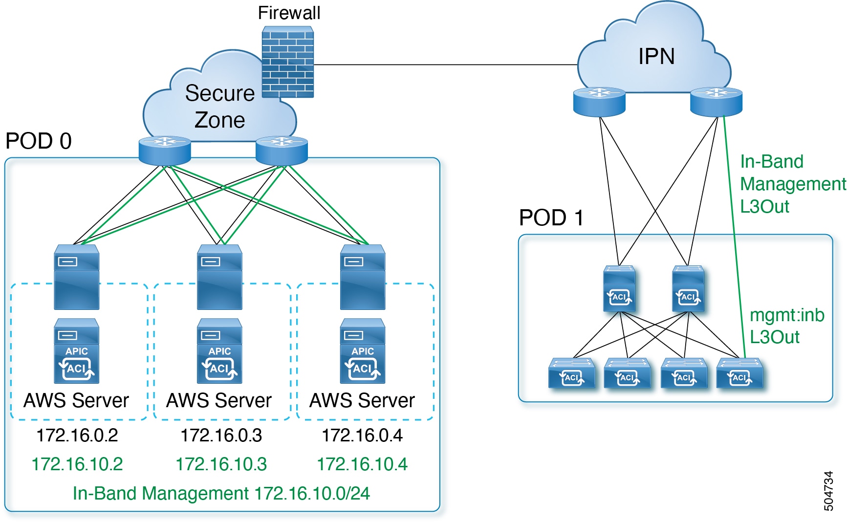
When you deploy in-band management with a layer 3 connected APIC cluster, the in-band management VRF (mgmt:inb) is not routed through the spines to the IPN. Connectivity to the in-band management interfaces on the APIC must be routed from an L3Out configured from the leaf switches. This L3Out should be configured in the mgmt tenant for the in-band management VRF.
Guidelines and Limitations for inband management for virtual APIC on AWS
-
During deployment, each APIC comes up with the inband management interfaces and IP addresses as allocated by AWS. Inband management interface is in disabled state. Inband management interface is enabled when inband policies are made available.
-
Inband IP address configuration cannot be changed by a user.
Procedure
|
Step 1 |
Configure the APIC upstream switches. Example: |
||
|
Step 2 |
Configure the APICs for in-band management using the normal in-band management configuration procedure.
For additional information about configuring in-band management, see the "Static In-band Management" chapter of the Cisco APIC and Static Management Access tech note. |
||
|
Step 3 |
Configure the APIC interfaces on the upstream switches. The APIC-connected interface must be a trunk interface. If the APICs were initialized with an infra VLAN other than 0, you can configure the interface as in the following example.
|
Migrating from a Physical APIC Cluster to a Virtual APIC Cluster on AWS
Use this procedure to migrate a physical APIC cluster to a virtual APIC cluster on AWS. Migration is only supported if both the APICs (physical and virtual) are remotely attached to the ACI fabric through a layer 3 network.
Procedure
|
Step 1 |
Export the config from a physical layer 3 cluster. On the Cisco APIC GUI, navigate to Admin > Import/ Export. For the detailed procedure, see Configuring an Export Policy Using the GUI. |
|
Step 2 |
Use the deployment procedure as explained earlier (Deploying Virtual APIC Using AWS), and create a virtual APIC cluster using AWS. Ensure the infra VLAN used in the physical APIC and the virtual APIC are the same. |
|
Step 3 |
Check if the physical cluster is healthy. |
|
Step 4 |
Import the configuration (from the physical to the virtual APIC) using the standard Cisco APIC GUI procedure. See Configuring an Import Policy Using the GUI.
|
|
Step 5 |
All the fabric nodes must be clean reloaded to join the new layer 3 virtual APIC cluster on AWS. |
|
Step 6 |
IPN must be manually updated with the infra IP addresses of the virtual APIC, so that virtual cluster is reachable from the ACI fabric nodes. |
Additional References
This cloud formation template automates the creation of pre-requisite configuration required to launch Cisco virtual APIC (vAPIC).
Metadata:
  "AWS::CloudFormation::Interface":
    ParameterGroups:
      - Label:
          default: VAPIC Network configuration
        Parameters:
          - VPCCidrBlock
          - AvailabilityZones
          - NumberOfAZs

    ParameterLabels:
      VPCCidrBlock:
        default: VPC CIDR
      AvailabilityZones:
        default: Availability Zones
      NumberOfAZs:
        default: Number of Availability Zones

Parameters:
  VPCCidrBlock:
    Description: VPC Cidr block used to launch VAPIC cluster
    Type: String
    AllowedPattern: "^(([0-9]|[1-9][0-9]|1[0-9]{2}|2[0-4][0-9]|25[0-5])\\.){3}([0])(\\/(24))$"
    Default: 10.1.0.0/24
    ConstraintDescription: "must be a valid IP unused VPC CIDR - x.x.x.x/24"

  AvailabilityZones:
    Description: >-
      List of Availability Zones used to launch vAPIC nodes. Choose 3 AZs for high
      availability. For regions that only supports 2 AZs, choose 2 AZs (2nd &
      3rd vAPIC will be launched in the second AZ). Make sure that the value of the
      NumberOfAZs parameter matches the number of selections
    Type: "List<AWS::EC2::AvailabilityZone::Name>"
  NumberOfAZs:
    AllowedValues:
      - "2"
      - "3"
    Default: "3"
    Description: >-
      Number of Availability Zones used to launch vAPIC cluster. This count must
      match the number of AZ selections you make from the AvailabilityZones
      parameter; otherwise, deployment will fail.
    Type: String

Conditions:
  IsAZ3Available: !Equals
    - !Ref NumberOfAZs
    - "3"
Resources:
  VPC:
    Type: AWS::EC2::VPC
    Properties:
      CidrBlock: !Ref VPCCidrBlock
      EnableDnsSupport: true
      EnableDnsHostnames: true
      Tags:
        - Key: Name
          Value: !Sub ${AWS::StackName}-vapic-vpc

  InternetGateway:
    Type: AWS::EC2::InternetGateway
    DependsOn: VPC
  AttachGateway:
    Type: AWS::EC2::VPCGatewayAttachment
    Properties:
      VpcId: !Ref VPC
      InternetGatewayId: !Ref InternetGateway

  #  subnets
  MgmtSubnet1:
    Type: AWS::EC2::Subnet
    Properties:
      VpcId: !Ref VPC
      AvailabilityZone: !Select
        - "0"
        - !Ref AvailabilityZones
      CidrBlock: !Select [0, !Cidr [!Ref VPCCidrBlock, 9, 4]]
      Tags:
        - Key: Name
          Value: !Sub ${AWS::StackName}-oob-mgmt-subnet-1

  InfraSubnet1:
    Type: AWS::EC2::Subnet
    Properties:
      VpcId: !Ref VPC
      AvailabilityZone: !Select
        - "0"
        - !Ref AvailabilityZones
      CidrBlock: !Select [3, !Cidr [!Ref VPCCidrBlock, 9, 4]]
      Tags:
        - Key: Name
          Value: !Sub ${AWS::StackName}-infra-subnet-1

  InbandSubnet1:
    Type: AWS::EC2::Subnet
    Properties:
      VpcId: !Ref VPC
      AvailabilityZone: !Select
        - "0"
        - !Ref AvailabilityZones
      CidrBlock: !Select [6, !Cidr [!Ref VPCCidrBlock, 9, 4]]
      Tags:
        - Key: Name
          Value: !Sub ${AWS::StackName}-inband-subnet-1

  MgmtSubnet2:
    Type: AWS::EC2::Subnet
    Properties:
      VpcId: !Ref VPC
      AvailabilityZone: !Select
        - "1"
        - !Ref AvailabilityZones
      CidrBlock: !Select [1, !Cidr [!Ref VPCCidrBlock, 9, 4]]
      Tags:
        - Key: Name
          Value: !Sub ${AWS::StackName}-oob-mgmt-subnet-2

  InfraSubnet2:
    Type: AWS::EC2::Subnet
    Properties:
      VpcId: !Ref VPC
      AvailabilityZone: !Select
        - "1"
        - !Ref AvailabilityZones
      CidrBlock: !Select [4, !Cidr [!Ref VPCCidrBlock, 9, 4]]
      Tags:
        - Key: Name
          Value: !Sub ${AWS::StackName}-infra-subnet-2

  InbandSubnet2:
    Type: AWS::EC2::Subnet
    Properties:
      VpcId: !Ref VPC
      AvailabilityZone: !Select
        - "1"
        - !Ref AvailabilityZones
      CidrBlock: !Select [7, !Cidr [!Ref VPCCidrBlock, 9, 4]]
      Tags:
        - Key: Name
          Value: !Sub ${AWS::StackName}-inband-subnet-2

  MgmtSubnet3:
    Condition: IsAZ3Available
    Type: AWS::EC2::Subnet
    Properties:
      VpcId: !Ref VPC
      AvailabilityZone: !Select
        - "2"
        - !Ref AvailabilityZones
      CidrBlock: !Select [2, !Cidr [!Ref VPCCidrBlock, 9, 4]]
      Tags:
        - Key: Name
          Value: !Sub ${AWS::StackName}-oob-mgmt-subnet-3

  InfraSubnet3:
    Condition: IsAZ3Available
    Type: AWS::EC2::Subnet
    Properties:
      VpcId: !Ref VPC
      AvailabilityZone: !Select
        - "2"
        - !Ref AvailabilityZones
      CidrBlock: !Select [5, !Cidr [!Ref VPCCidrBlock, 9, 4]]
      Tags:
        - Key: Name
          Value: !Sub ${AWS::StackName}-infra-subnet-3

  InbandSubnet3:
    Condition: IsAZ3Available
    Type: AWS::EC2::Subnet
    Properties:
      VpcId: !Ref VPC
      AvailabilityZone: !Select
        - "2"
        - !Ref AvailabilityZones
      CidrBlock: !Select [8, !Cidr [!Ref VPCCidrBlock, 9, 4]]
      Tags:
        - Key: Name
          Value: !Sub ${AWS::StackName}-inband-subnet-3

Outputs:
  VAPICVPC:
    Description: VPC ID.
Value: !Ref VPC Feedback