New and Changed Information
The following table provides an overview of the significant changes up to this current release. The table does not provide an exhaustive list of all changes or of the new features up to this release.
|
Cisco APIC Release Version |
Feature |
Description |
|---|---|---|
|
5.2(4) |
First release of this document |
-- |
Overview
This feature provides fast convergence for a destination that is reachable using a primary route and fallback route. You can group multiple next-hops of a route into one fallback route group so that if next-hop of the primary route fails, a Cisco ACI leaf switch can replace the failed primary next-hop with all the next-hops of the group in the hardware table before the control plane convergence with the routing protocol happens. This hardware-based convergence can happen within a second compared to multiple seconds or minutes for convergence through the control plane. In addition, next-hop failures can be detected faster through BFD.
This feature is useful in the Telco packet core deployment and described in detail in the following sections.
Typical Deployment
 Note |
This document assumes that you are adding fallback route configuration to an already deployed and configured fabric, so configuration for L3Outs, VRFs, and other fabric elements are outside the scope of this guide. |
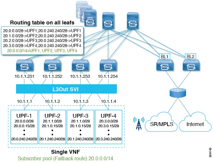
The following diagram illustrates the typical existing deployment, where UPF-1 through UPF-4 are all advertising the same subnet subscriber pool 20.0.0.0/14. Since all of them are advertising the same subnet, the traffic can come to any UPF (for example, UPF-3) and then it would have to go through the fabric if that UPF is not the UPF which has the session information (in this case,
UPF-1).

In order to mitigate this additional traffic, each UPF is typically configured to advertise a /28 subnet along with the fallback route (20.0.0.0/14), which is the subscriber pool. In other words, there's a common subnet and a smaller subnet to allow the border leaf (BL)
to be able to determine the primary subnet and direct the traffic to the correct UPF, as shown in the following figure. Fallback
route is used only when the primary route (/28 subnet) is down.
The downside of this approach is the high prefix scale and high convergence times due to the control plane having to remove primary route and install fallback route into hardware.
To mitigate these issues, you can update your existing deployment to configure fallback route groups at the VRF level and associate them with an L3Out. Each group will have a fallback route and all the associated next-hops of the UPFs. Each next-hop can be a directly connect interface IPs or a loopback IPs of the UPFs depending on whether eBGP is configured with directly connected interfaces or loopback interfaces.
Benefits of Using Fallback Route Groups
Beginning with Release 5.2(4), you can configure fallback route groups as an alternative to the typical deployment described above to eliminate unnecessary traffic forwarded between UPFs and reduce convergence times in case of a UPF failure.
In this case, multiple UPFs are combined into a fallback route group, so if any one UPF fails, the convergence will occur within the hardware itself significantly reducing the convergence times.
Fallback Routes Functionality, Failure Recovery, and Configuration Workflow
This section describes fallback route groups configuration workflow and failover mechanism.
-
Initial configuration and route deployment in Cisco ACI hardware:
-
You configure fallback route group at the VRF level and associate it with the L3Out in your APIC GUI.
-
The group will have the fallback route and all the associated next-hops of the UPFs
-
Each next-hop can be a directly connect interface IPs or a loopback IPs of the UPFs depending on whether eBGP is configured with directly connected interfaces or loopback interfaces
-
Fallback route is pointing to all the UPFs in the group as it is advertised by all the UPFs.
-
Primary routes are pointing to only one of the UPFs based on the distribution.
-
-
UPF Failure Handling:
-
If a UPF failure is detected by BFD (for example,
UPF-1in the below illustration), the fabric will automatically replace the failed next-hop with remaining next-hops of the UPFs from fallback route in hardware. -
All hardware tables are updated with remaining UPF next-hops before control plane convergence by BGP.
At this point, route table still has all primary prefixes advertised by BGP.
Figure 3. Hardware-based Convergence 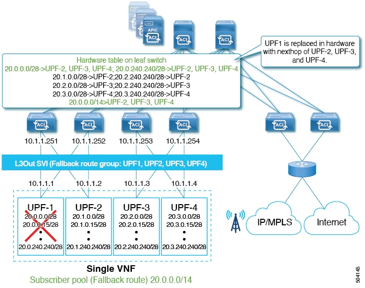
-
After Control Plane convergence, BGP removes all the primary prefixes advertised from
UPF-1.Figure 4. Control Plane Convergence 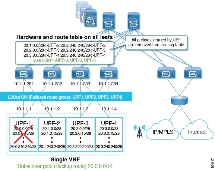
-
Guidelines and Limitations
When configuring fallback routes, the following guidelines apply:
-
This feature is supported starting with Cisco APIC, Release 5.2(4).
-
This feature is supported with the following switches:
-
-FXand later leaf switches -
-EXand later spine switches as well as theN9332CandN9364Cfixed spine switches.
-
-
The same fallback route is used by all UPFs in the cluster.
In other words, there is no traffic impact if the fabric forwards traffic to all remaining next-hops (UPFs) in the event of the UPF failure.
-
Fallback routes are not supported over floating L3Out.
-
Fallback routes are not supported for Multi-Site traffic.
-
Fallback routes are supported on L3Out SVI only.
-
Stretching SVIs is not supported across local leaf (LL) and remote leaf (RL).
Note that this is an existing limitation and not a limitation specific to the fallback route group feature.
-
If BGP route next-hop is reachable via OSPFv3 route, the OSPFv3 route next-hops must be global IPv6 addresses and not Link Local addresses.
Creating Fallback Route Groups
This section explains how to create a fallback route group.
Procedure
| Step 1 |
From the top navigation bar, choose . |
| Step 2 |
Add a new fallback route group. 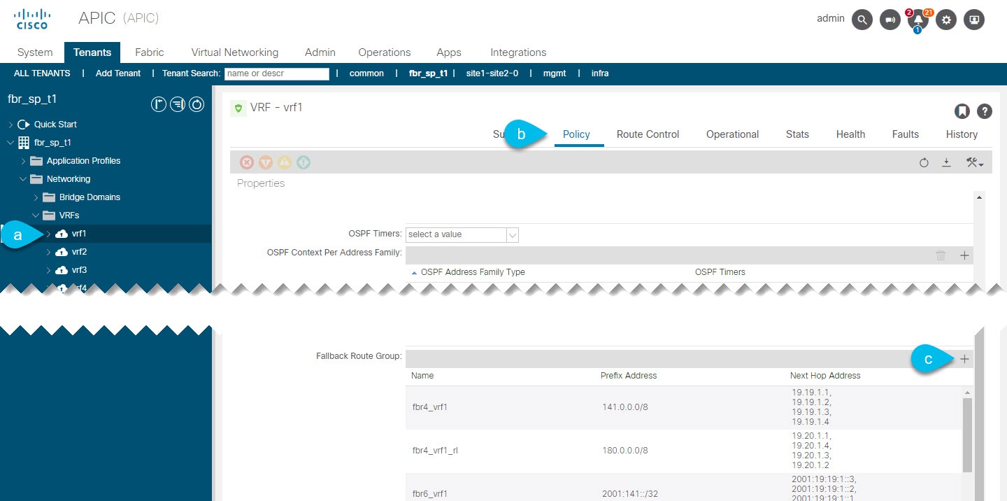 |
| Step 3 |
In the Create Fallback Route Group window, provide the required details. |
What to do next
Attaching Fallback Route Policy to L3Out
This section describes how to attach a fallback route policy to an L3Out.
Note |
When you configure fallback route policy on an L3out, all nodes in the L3Out are configured with the same fallback route policy. |
Before you begin
-
An L3Out already created and configured.
The L3Out must be in a physical domain, not in a VMM domain.
-
A fallback route policy created, as described in Creating Fallback Route Groups.
Procedure
| Step 1 |
From the top navigation bar, choose . |
| Step 2 |
Associate the fallback route group with the L3Out. 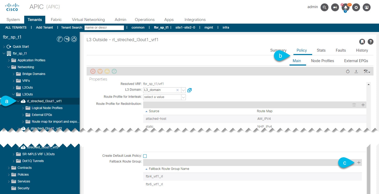 |
What to do next
Enabling Next Hop Propagation and Multipath
This section explains to enable next-hop propagation which is required for fallback routes to work as well as multipath if multiple next-hops are present.
Procedure
| Step 1 |
From the top navigation bar, choose . |
| Step 2 |
Associate the fallback route group with the L3Out. 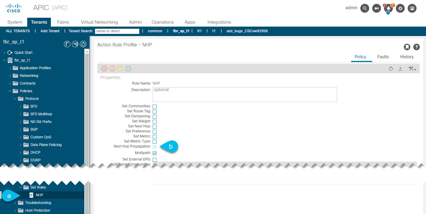 |
What to do next
Configuring Attached-Host Route Redistribution
In this procedure, you will specify the attached-host routes or subnets connected to the SVIs that need to be redistributed into the MP-BGP fabric.
If you plan to configure static route redistribution, skip this section and follow the steps described in Configuring Static Route Redistribution instead.
Procedure
| Step 1 |
Create a match rule for the route map for route control for the attached-host redistribution policy. |
| Step 2 |
Create a route map for route control for the attached-host redistribution policy. |
| Step 3 |
Attach the policy to the L3Out.
|
Configuring Static Route Redistribution
In this procedure, you will be configuring the route map for static routes that need to have the next hop propagated into the MP-BGP fabric.
If you plan to configure static route redistribution, skip this section and follow the steps described in Configuring Attached-Host Route Redistribution instead.
Procedure
| Step 1 |
Configure the maximum number of paths for the redistribution of routes in the ACI fabric. This is a necessary step before you can configure the Multipath field. |
| Step 2 |
Create a match rule for the route map for route control for static redistribution on the L3Out. |
| Step 3 |
Create a route map for route control for static redistribution on the L3Out. |
| Step 4 |
Attach the policy to the L3Out.
|
Verifying Configuration
This section describes how to verify that the configuration was deployed correctly using the APIC's managed object (MO) browser.
Procedure
| Step 1 |
Open the Object Store browser. You can verify the MOs using the Object Store browser, which you can open by clicking the Help and Tools icon in the top right of your UI and selecting Object Store browser or by navigating directly to |
| Step 2 |
Verify that the fallback route group concrete MOs were created. |
| Step 3 |
Verify that the fallback route group resolved MOs were created. There are two types of resolved MOs—one under In the case where one FBR group is associated with multiple L3Outs, a reference count MO |
| Step 4 |
Check for any fallback route faults. You can check any faults raised for the fallback route group in the APIC UI by navigating to the L3Out where the group is attached and selecting the Faults tab. There is a single fault that may be raised for the fallback route feature if a route is not present in the fallback route group. |
 Feedback