Maintaining the Cisco uBR-MC3GX60V-RPHY Line Card
Available Languages
Contents
- Maintaining the Cisco uBR-MC3GX60V-RPHY Line Card
- Removing and Replacing the SFP Module from the Cisco uBR-MC3GX60V-RPHY Line Card
- Removing an SFP Module from the Existing Line Card
- Installing an SFP Module on the Cisco uBR-MC3GX60V-RPHY Line Card
- Removing and Replacing the Cisco uBR-MC3GX60V-RPHY Line Card
- Removing the Existing Line Card from the Card Slot
- Installing the Cisco uBR-MC3GX60V-RPHY Line Card in the Card Slot
- Online Insertion and Removal of the Cisco uBR-MC3GX60V-RPHY Line Card
Maintaining the Cisco uBR-MC3GX60V-RPHY Line Card
Removing and Replacing the SFP Module from the Cisco uBR-MC3GX60V-RPHY Line Card
Removing an SFP Module from the Existing Line Card
Before You BeginProcedureHave the following tools and supplies ready before performing this task:
Caution
Removing and inserting an SFP module frequently can damage the SFP module. Do not remove and insert the SFP modules unless absolutely necessary.
What to Do Next
- To remove the existing line card, see Removing the Existing Line Card from the Card Slot.
- To install an SFP module on the Cisco uBR-MC3GX60V-RPHY line card, see Installing an SFP Module on the Cisco uBR-MC3GX60V-RPHY Line Card
Installing an SFP Module on the Cisco uBR-MC3GX60V-RPHY Line Card
Before You BeginProcedureEnsure that the Cisco uBR-MC3GX60V-RPHY line card is installed in the Cisco CMTS chassis. See Installing the Cisco uBR-MC3GX60V-RPHY Line Card in the Card Slot.
Have the following tools and supplies ready before performing this task:
For more information on SFP modules that are supported on the Cisco uBR-MC3GX60V-RPHY line card, see SFP Modules for the Cisco uBR-MC3GX60V-RPHY Line Card.
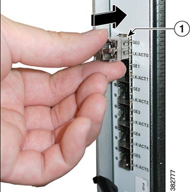
Step 1 Attach an ESD-preventive wrist strap to your wrist. Step 2 Remove the SFP module from its protective packaging. Step 3 Locate the transmit (Tx) and receive (Rx) markings on the top side of the SFP module.
Note On some SFP modules, the Tx and Rx markings might be replaced by arrowheads pointing from the SFP connector (transmit direction or Tx) and towards the connector (receive direction or Rx). Step 4 Align the SFP module in front of the socket opening. Step 5 Insert the SFP module into the socket until you feel the SFP module connector snap into the socket connector and then close the SFP latch.
Note For optical SFP modules, following are the guidelines to remove the dust plugs and make any optical connections:
- Do not remove the protective dust plugs on the unplugged fiber-optic cable connectors and the transceiver optical bores until you are ready to make a connection.
- inspect and clean the LC connector end-faces just before you make any connections.
- Grasp the LC connector housing to plug or unplug a fiber-optic cable.
Step 6 Remove the dust plug from the SFP module and keep it safe for future use.
Note Leave the dust plug in the SFP module port if a cable is not being installed.
What to Do Next
To connect the network cable to an SFP module, see Connecting a Network Cable to an SFP Module.
Removing and Replacing the Cisco uBR-MC3GX60V-RPHY Line Card
Removing the Existing Line Card from the Card Slot
Before You BeginProcedure
- Remove the SFP module from the line card. See Removing an SFP Module from the Existing Line Card.
- Delete the existing configurations on the PRE using the no card command.
Have the following tools and supplies ready before performing this task:
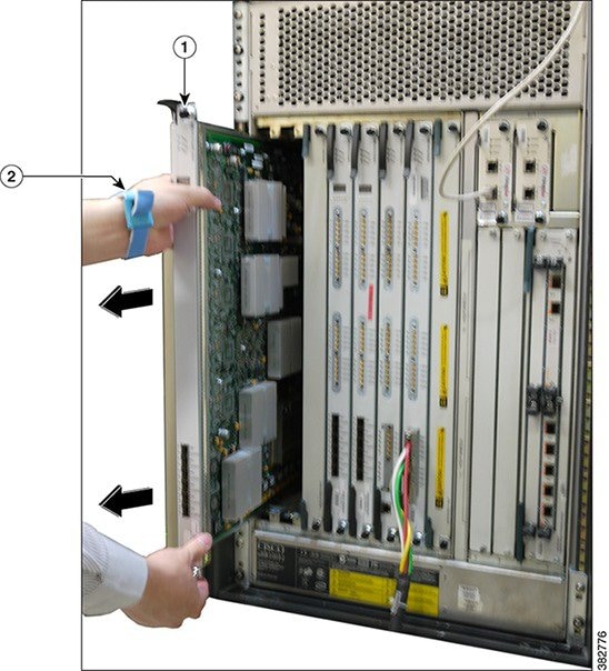
Step 1 Attach an ESD-preventive wrist strap to your wrist. Step 2 Unscrew the top and bottom captive screws on the line card using a T-10 Torx driver tool or flathead screwdriver. Step 3 Simultaneously pivot both ejector levers away from the line card to disengage the line card from the chassis. Step 4 Slide the line card out of the slot in the chassis. Place it on an antistatic surface or in a static shielding bag with the component side up.
Caution Do not drop the line card. Dropping the line card can damage the carrier rails and card guides and prevent the reinstallation.
What to Do Next
Perform one of the following:
- Install a new or replacement Cisco uBR-MC3GX60V-RPHY line card, see installing the line card.
- Install a Blank card slot cover over the slot and tighten the captive screws, if you are not installing any line card in the slot. This ensures to keep dust out of the chassis and maintain proper airflow through the line card compartment.
Installing the Cisco uBR-MC3GX60V-RPHY Line Card in the Card Slot
Before You BeginProcedure
- Ensure that the existing line card or the Blank card slot cover is removed. See Removing the Existing Line Card from the Card Slot.
- Ensure that you attach an ESD-preventive wrist strap to your wrist.
- For Class B emission compliance requirements, the two ferrites available in the CMTS accessory kit must be installed on the input DC power harness of the chassis. These ferrite beads are clamp-on type and should be placed as close to the input DC power connector (DC input terminal connector) as possible.
Have the following tools and supplies ready before performing this task:
Step 1 Attach an ESD-preventive wrist strap to your wrist. Step 2 Choose an available slot (5/0 to 8/0) for the line card and carefully align the upper and lower edges of the Cisco uBR-MC3GX60V-RPHY line card with the upper and lower guides in the chassis.
Caution The Cisco uBR-MC3GX60V-RPHY line card weighs 13 lbs. Use both hands when handling the Cisco uBR-MC3GX60V-RPHY line card. Do not drop the line card to avoid damaging the carrier rails. Bent or damaged rails can damage the line card guides and prevent line card installation. When installing line cards for the first time, or when all the captive screws of the line card are loose, insert cards first in slot 5/1 and work towards slot 8/0 to prevent uneven gasket pressure.
Step 3 Slide the Cisco uBR-MC3GX60V-RPHY line card into the slot until it is firmly seated in the chassis. Step 4 Close the ejector levers to secure the Cisco uBR-MC3GX60V-RPHY line card. Step 5 Engage and tighten the captive screws with your fingers. Then, use either a T-10 Torx driver tool or a common flathead screwdriver to tighten the captive screws from 5 to 7 in-lbs.
What to Do Next
To install the SFP module, see Installing an SFP Module on the Cisco uBR-MC3GX60V-RPHY Line Card.
Online Insertion and Removal of the Cisco uBR-MC3GX60V-RPHY Line Card
Before You BeginProcedure
- Save the Cisco uBR-MC3GX60V-RPHY line card configurations before starting the OIR.
- Change the standby card (if available) to HOT state.
- Save the startup configuration file before any reload of the system (if there is a need to reload), after a successful OIR.
- Perform OIR when the Cisco CMTS is up and running.
Step 1 Enter the cr10k card oir-compatibility command for the existing Cisco uBR-MC3GX60V-RPHY line card.
Example:Router(config)# cr10k card 8/0 oir-compatibilityThis command preserves the configuration and performs internal synchronization to ensure that the OIR runs successfully.
Step 2 Save the configuration to ensure the transition.
Example:Router# copy running-config startup-configStep 3 Power down the existing Cisco uBR-MC3GX60V-RPHY line card using cable power off command.
Example:Router# cable power off 8/0 Line Card 8/0 is POWERED OFFThis powers off the Cisco uBR-MC3GX60V-RPHY line card gracefully.
Step 4 Before removing the existing Cisco uBR-MC3GX60V-RPHY line card, verify that the proper grounding instructions have been followed. Step 5 Remove the existing Cisco uBR-MC3GX60V-RPHY line card from the slot. Step 6 Install the new Cisco uBR-MC3GX60V-RPHY line card in the slot. See Installing the Cisco uBR-MC3GX60V-RPHY Line Card in the Card Slot.
Step 7 Power up the new Cisco uBR-MC3GX60V-RPHY line card using the cable power on command.
Example:Router# cable power on 8/0Step 8 Verify that the new Cisco uBR-MC3GX60V-RPHY line card and line protocol is up using the show interface cable command.
Example:Router# show interface cable 8/0/0 Cable8/0/0 is up, line protocol is up Hardware is BCM3210 ASIC, address is 010a.13e8.1ca8 (bia 010a.13e8.1a60) Internet address is 192.1.1.3/24 MTU 1500 bytes, BW 27000 Kbit, DLY 1000 usec, rely 255/255, load 1/255 Encapsulation, loopback not set, keepalive not set ARP type: ARPA, ARP Timeout 04:00:00 Last input 4d07h, output 00:00:00, output hang never Last clearing of "show interface" counters never Queuing strategy: fifo Output queue 0/40, 0 drops; input queue 0/75, 0 drops 5 minute input rate 1834000 bits/sec, 2385 packets/sec 5 minute output rate 1982000 bits/sec, 2431 packets/sec 24461542 packets input, 2348214388 bytes, 0 no buffer Received 1979 broadcasts, 0 runts, 0 giants, 0 throttles 0 input errors, 0 CRC, 0 frame, 0 overrun, 0 ignored, 0 abort 24854257 packets output, 2536222931 bytes, 0 underruns 0 output errors, 0 collisions, 0 interface resets 0 output buffer failures, 0 output buffers swapped outStep 9 Verify the hardware status using the show controllers cable command.
Example:Router# show controllers cable 8/0/0 Cable8/0/0 JIB hardware status: JIB Downstream port Enabled JIB Upstream port 0 Enabled JIB Upstream port 1 Enabled JIB Upstream port 2 Enabled JIB Upstream port 3 Enabled Cable8/0/0 Upconverter is Enabled Output is EnabledStep 10 Verify the configuration with the show running-configuration command.
Notices
Copyright © 2014, Cisco Systems, Inc. All rights reserved.


 Feedback