-
null
- ACE Appliance Device Manager Overview
- Information About the ACE No Payload Encryption Software Version
- Finding Information on CLI Tasks
- Logging into ACE Appliance Device Manager
- Changing Your Account Password
- ACE Appliance Device Manager Interface Overview
- Configuration Overview
- Understanding ACE Features
- IPv6 Considerations
- Understanding ACE Appliance Device Manager Terminology
Overview
This chapter contains the following sections:
- ACE Appliance Device Manager Overview
- Information About the ACE No Payload Encryption Software Version
- Finding Information on CLI Tasks
- Logging into ACE Appliance Device Manager
- Changing Your Account Password
- ACE Appliance Device Manager Interface Overview
- Configuration Overview
- Understanding ACE Features
- IPv6 Considerations
- Understanding ACE Appliance Device Manager Terminology
For more information on how to get started quickly, see the Quick Start Guide, Cisco ACE 4700 Series Application Control Engine Appliance .
ACE Appliance Device Manager Overview
The ACE Appliance Device Manager, which resides in flash memory on the ACE appliance, provides a browser-based interface for configuring and managing the ACE appliance. Its intuitive interface combines easy navigation with point-and-click provisioning of services, reducing the complexity of configuring virtual services and multiple feature sets.
ACE Appliance Device Manager menus and options:
- Supports end-to-end service provisioning of the ACE appliance and any associated virtual contexts, including network access, port management, application acceleration and optimization, load-balancing, SSL management, resource management, and fault tolerance.

Note Device Manager uses SSH and XML over HTTPS to communicate with the ACE appliance and applying exec mode configuration changes (such as, checkpoint, SSL certificate, license, copy, and backup and restore configurations) to the appliance. By default, SSH is enabled on the appliance. However, ensure that the ssh key rsa 1024 force command is applied on the appliance.
- Helps you manage ACE appliance licenses and role-based access control (RBAC).
- Provides a monitoring interface with a flexible choice of statistics and graphs.
- Enables you report any problem with the ACE appliance using the Lifeline feature, which allows you to forward critical information about the problem to Cisco Technical Support.
- Offers task-based context-sensitive help from each screen, providing information about fields on the screen and related procedures.
For more information on how to get started quickly, see the Getting Started Guide, Cisco ACE 4700 Series Application Control Engine Appliance .
Information About the ACE No Payload Encryption Software Version
Beginning with ACE software Version A5(2.0), Cisco makes available the following two ACE software versions:
- ACE Payload Encryption (PE)—CLI commands related to payload encryption protocols are enabled. The ACE uses the payload encryption protocols to encrypt through-the-box traffic, such as IPsec, SSL VPN, and other secure voice protocols. The ACE PE software version contains the same payload encryption functionality found in previous ACE software versions.
- ACE No Payload Encryption (NPE)—CLI commands related to payload encryption protocols are either removed or do not function because the key encryption configuration commands have been removed. The new ACE NPE software version supports customers located in countries where the United States has imposed export restrictions on crypto functions. Without the use of payload encryption protocol commands, you cannot configure the ACE to perform data encryption tasks, such as configuring it as a virtual Secure Sockets Layer (SSL) server for SSL initiation or termination.
Modifications made to the ACE NPE software version do not affect management protocols, such as SSH, which is required to access the Device Manager GUI. For more information, see the “Using the Setup Script to Enable Connectivity to the Device Manager” section in the Cisco 4700 Series Application Control Engine Appliance Administration Guide .
When using the ACE NPE software version, Device Manager includes the following modifications:
- The SSL configuration tab (Config > Virtual Contexts > SSL) is removed to prevent access to the main SSL configuration windows.
- In GUI sections that typically contain encryption-related configuration attributes, the attributes are either removed or you are not permitted to configure them. If you attempt to configure an encryption-related attribute, Device Manager does not allow you to deploy the configuration.
- In GUI sections that display monitored attributes that include encryption-related attributes (such as SSL connection rate), the encryption-related attributes may be listed but do not show any values associated with them.
This guide and the Device Manager online help contain notes where information about encryption-related attributes is affected when using the ACE NPE software version.
Finding Information on CLI Tasks
ACE Appliance Device Manager does not include a one-to-one mapping of all the possible command line interface (CLI) tasks for the ACE appliance. Table 1-1 identifies some of the individual tasks to be performed from the CLI and provides a reference to the applicable configuration guide. For tasks not found in this table, see the Getting Started Guide, Cisco ACE 4700 Series Application Control Engine Appliance .
|
|
|
|---|---|
Routing and Bridging Guide, Cisco ACE Application Control Engine |
|
Security Guide, Cisco ACE Application Control Engine Chapter 2, Configuring Authentication and Accounting Services |
|
Date and time (time zone, daylight savings time, clock settings, and NTP) |
|
Security Guide, Cisco ACE Application Control Engine Chapter 2, Configuring Authentication and Accounting Services |
|
Security Guide, Cisco ACE Application Control Engine Chapter 2, Configuring Authentication and Accounting Services |
|
script file 1 |
|
Security Guide, Cisco ACE Application Control Engine Chapter 2, Configuring Authentication and Accounting Services |
|
Routing and Bridging Guide, Cisco ACE Application Control Engine |
Note When you use the ACE CLI to configure named objects (such as a real server, virtual server, parameter map, class map, health probe, and so on), consider that the Device Manager (DM) supports object names with an alphanumeric string of 1 to 64 characters, which can include the following special characters: underscore (_), hyphen (-), dot (.), and asterisk (*). Spaces are not allowed.
If you use the ACE CLI to configure a named object with special characters that the DM does not support, you may not be able to configure the ACE using DM.
Logging into ACE Appliance Device Manager
You access ACE Appliance Device Manager features and functions through a Web-based interface. The following sections describe logging in, the interface, and terms used in ACE Appliance Device Manager.
By default, your ACE provides an Admin context and five user contexts, which allow you to use multiple contexts if you choose to configure them. ACE Appliance Device Manager uses Hypertext Transfer Protocol Secure (HTTPS) to securely encrypt HTTP requests and responses.
The ACE Appliance Device Manager login screen allows you to do the following:
- Log into the ACE Appliance Device Manager interface (First Time Login or Logging In as a User)
- Change the password for your account (See Changing Your Account Password.)
- Obtain online help by clicking Help
We recommend that before you log into the ACE Appliance Device Manager that you log in to the ACE appliance CLI and initially configure basic settings on the ACE. See the Administration Guide, Cisco ACE Application Control Engine , Chapter 1, Setting Up the ACE, for details.
Note![]() The DM does not support duplicate management IP addresses in different contexts.
The DM does not support duplicate management IP addresses in different contexts.
First Time Login
After you perform the initial setup of the ACE appliance using the CLI, use the following procedure to log in the first time.
Step 1![]() Use a Web browser and navigate to the ACE Appliance Device Manager login screen by typing the IP address of the management interface configured during initial setup, such as https://192.168.11.1. A security alert screen appears.
Use a Web browser and navigate to the ACE Appliance Device Manager login screen by typing the IP address of the management interface configured during initial setup, such as https://192.168.11.1. A security alert screen appears.
Note The DM does not support duplicate management IP addresses in different contexts.
Step 2![]() We recommend that you view the certificate to confirm it is from Cisco Systems, and then click OK or Yes to accept the certificate and proceed to the login screen. The keys you select may be different based on your browser.
We recommend that you view the certificate to confirm it is from Cisco Systems, and then click OK or Yes to accept the certificate and proceed to the login screen. The keys you select may be different based on your browser.
Step 3![]() In the User Name field, type admin .
In the User Name field, type admin .
The admin account was created when the system was installed. Once you are logged in using this account, you can create additional user accounts and manage virtual contexts, roles, and domains. For information on changing account passwords, see Changing User Passwords.
Step 4![]() In the Password field, type the password for the admin user account, admin. The password for the admin user account was configured when the system was installed. Change the default admin login password as outlined in Changing Your Account Password.
In the Password field, type the password for the admin user account, admin. The password for the admin user account was configured when the system was installed. Change the default admin login password as outlined in Changing Your Account Password.
Note All ACE appliances shipped from Cisco Systems are configured with the same administrative username and password. If you do not change the default Admin password, you will only be able to log in to the ACE through the console port.
When you log in, the default page that appears is the DM Homepage (see Chapter 2, “Using Homepage”).
Step 6![]() We recommend you change your admin password. See Changing Your Account Password.
We recommend you change your admin password. See Changing Your Account Password.
Logging In as a User
Step 1![]() Use a web browser and navigate to the ACE Appliance Device Manager login screen by typing the IP address of the management interface of a virtual context you wish to login into, such as https://192.168.11.1. The login screen appears.
Use a web browser and navigate to the ACE Appliance Device Manager login screen by typing the IP address of the management interface of a virtual context you wish to login into, such as https://192.168.11.1. The login screen appears.
Note The DM does not support duplicate management IP addresses in different contexts.
Step 2![]() To login as a user, enter userid in the User Name field (where userid is the login name provided by your admin).
To login as a user, enter userid in the User Name field (where userid is the login name provided by your admin).
Step 3![]() Enter your password and click Login .
Enter your password and click Login .
Changing Your Account Password
All ACE appliances are shipped from Cisco Systems with the same administrative username and password. If you do not change the default Admin password, you will only be able to log in to the ACE through the console port.
Use this procedure to change your account password.
Step 1![]() Using a Web browser, navigate to the ACE Appliance Device Manager login screen by typing the IP address of the management interface configured during initial setup, such as https://192.168.11.1. The login screen appears.
Using a Web browser, navigate to the ACE Appliance Device Manager login screen by typing the IP address of the management interface configured during initial setup, such as https://192.168.11.1. The login screen appears.
Note The DM does not support duplicate management IP addresses in different contexts.
Step 2![]() In the User Name field, enter your account user name.
In the User Name field, enter your account user name.
Step 3![]() Click Change Password . The Change Password configuration screen appears.
Click Change Password . The Change Password configuration screen appears.
Step 4![]() In the User Name field, enter the user name of the account you want to modify.
In the User Name field, enter the user name of the account you want to modify.
For a user name in a context other than the Admin context, you must include the context name after the user name in the following format: username @ context_name
For example, for the test_1 user name in the C1 context, enter test_1@C1.
Step 5![]() In the Old Password field, enter the current password for this account.
In the Old Password field, enter the current password for this account.
Step 6![]() In the New Password field, enter the new password for this account.
In the New Password field, enter the new password for this account.
Password attributes such as minimum and maximum length or accepted characters are defined at the appliance level. Valid passwords are unquoted text strings with a maximum of 64 characters.
Step 7![]() In the Confirm New Password field, reenter the new password for this account.
In the Confirm New Password field, reenter the new password for this account.
ACE Appliance Device Manager Interface Overview
When you log into the ACE Appliance Device Manager, the default window that appears is the Homepage from which you can access the operational and monitoring features of DM. For details about using Homepage, see Chapter 2, “Using Homepage”).
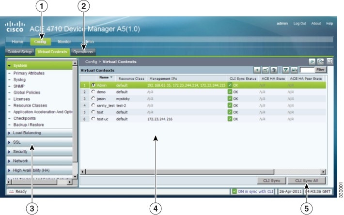
Figure 1-1 is the All Virtual Contexts table ( Config > Virtual Contexts) as an example of the DM interface components. Table 1-2 describes the numbered fields. A description of the buttons in the ACE Appliance Device Manager window are in Table 1-4.
Features that are not accessible from your user login or context due to permission settings will not display or may display grayed out. For more details on roles and features, see Managing User Roles.
Figure 1-1 ACE Appliance Device Manager Interface Components
|
|
|
|---|---|
Navigation pane, which contains:
|
|
A second-level navigation path, which contains another level of navigation. Clicking an option in this submenu displays its associated menus in the navigation pane. |
|
Third-level navigation pane, which contains additional levels of navigation. Clicking on the menu bar in this pane toggles the task menu display options. |
|
Content area, which contains the display and input area of the window. It can include tables, graphical maps, configuration screens, graphs, buttons, or combinations of these items. For a description of buttons, see Table 1-4. |
|
Status bar, which displays Device Manager and CLI synchronization information, polling status for a context, and the current date and time of the ACE appliance. Note Time values are displayed using a fixed time zone (GMT). The Device Manager automatically converts the timezone setting of the ACE appliance to GMT and displays the GMT string adjacent to the current time. |
Understanding ACE Appliance Device Manager Screens and Menus
Figure 1-2 contains many common screen elements as described in Table 1-3 .
Figure 1-2 Example ACE Appliance Device Manager Screen

|
|
|
|---|---|
The high-level navigation path within the ACE Appliance Device Manager interface, which includes Config, Monitor, and Admin functions. You can click a tab in the navigation path to view the next level of menus below the tabs. |
|
Content area. Contains the display and input area of the window. It can include tables, graphical maps, configuration screens, graphs, buttons, or combinations of these items. |
|
Content buttons, which are described in Table 1-4 . |
|
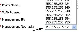
Input fields. Use these fields to make selections and provide information. Fields with 2 or 3 options use radio buttons. Fields with more than 3 options use dropdown lists. |
|
Synchronization and configuration section of the status bar. One indicator displays DM GUI and CLI synchronization and summary count information and the other indicator displays CLI synchronization information and polling status for a context. See Viewing Virtual Context Synchronization Status for CLI Config Status message descriptions or Error Monitoring for polling state message descriptions. |
Understanding ACE Appliance Device Manager Buttons
Table 1-4 describes the buttons that appear in some of the Config, Monitor, and Admin screens.
Note![]() ACE Appliance Device Manager documentation, including online help, uses the names of buttons in all procedures. For example, “ClickBack to return to the previous screen.”
ACE Appliance Device Manager documentation, including online help, uses the names of buttons in all procedures. For example, “ClickBack to return to the previous screen.”


Understanding Table Buttons
When the content area of the ACE Appliance Device Manager screen contains a table, there are several buttons that appear as described in Table 1-5.
|
|
|
|
|---|---|---|

|
||

|
Opens the configuration screen of a selected entry in the table. |
|

|
||

|
Filters the displayed list of items according to the criteria you specify. (See Filtering Entries.) |
|

|
Appears when filtering is enabled; updates the table with the filtering criteria. |
|

|
Displays the current information in a new window in either raw data or Excel format so you can save it to a file or print it. |
Conventions in Tables
Double-clicking an entry in a table opens its corresponding configuration screen.
You can select multiple entries in a table in two ways:
- To select all table entries, check the check box at the top of the first column (where available).
- To select multiple entries individually, select the desired entries.
If you select multiple entries in a table and then choose an option that can apply to only one entry at a time, the Parent Row field appears first in the configuration screen (see Figure 1-3).
The Parent Row field lists the selected entries and requires you to select one. Subsequent configuration choices in this screen are applied only to the entry identified in the Parent Row field.
Parent Row columns appear in subtables when multiple items are selected in the primary table.
Figure 1-3 Parent Rows in Configuration Screens
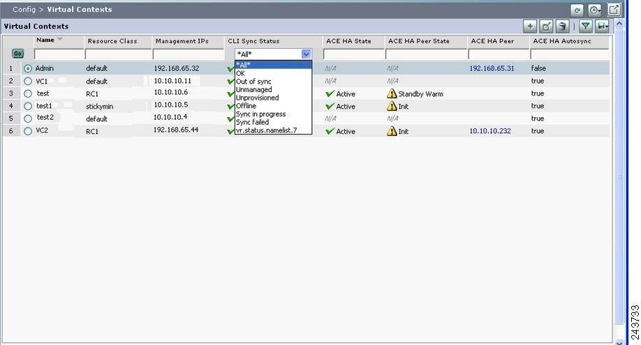
Click Filter to view table entries using criteria you select. When filtering is enabled, a filter row appears above the first table entry that allows you to filter entries in the following ways:
- In a drop-down list, select one of the ACE Appliance Device Manager-identified categories (see Figure 1-4). The table refreshes automatically with the entries that match the selected criterion.
- In fields without drop-down lists, enter the string you want to match, and then click Go above the first table entry. The table refreshes with the entries that match your input.
Figure 1-4 Example Table with Filtering Enabled
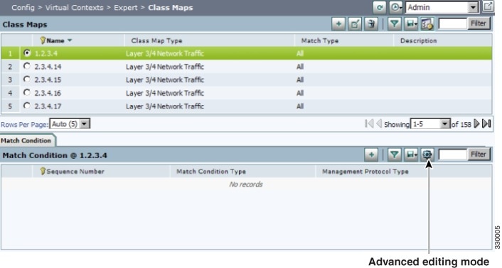
Using the Advanced Editing Option
By default, tables include columns that contain configured attributes, or a subset of columns related to a key field.
To view all configurable attributes in table format, click Advanced Editing Mode (the highlighted button in Figure 1-5). When advanced editing mode is enabled, all columns appear for your review (see Figure 1-5).
Figure 1-5 Advanced Editing Enabled Screen
ACE Appliance Device Manager Screen Conventions
Table 1-6 describes other conventions used in ACE Appliance Device Manager screens.


Viewing Monitoring Results
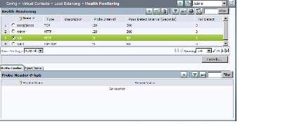
Figure 1-6 shows an example graph from the Monitor component.
Figure 1-6 Monitoring Results Screen
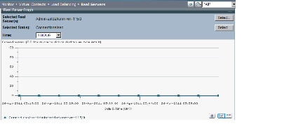
Monitor graphs offer many options including graph type, viewing raw data, graph layout, and values to be included. Table 1-7 identifies these options and their associated buttons. When viewing a graph, click the button to select the option. ACE Appliance Device Manager displays graph data in GMT.
Note![]() The maximum number of statistics that can be graphed is five.
The maximum number of statistics that can be graphed is five.
Note![]() On the ACE, statistics are kept for 7 days or 20,000 hourly records, whichever comes first. The duration it takes to reach 20,000 hourly records is determined by the number of contexts, interfaces and real servers configured. The “All dates” graph provides all available data in the database, up to the above mentioned numbers. An ACE reboot will reset the statistics database.
On the ACE, statistics are kept for 7 days or 20,000 hourly records, whichever comes first. The duration it takes to reach 20,000 hourly records is determined by the number of contexts, interfaces and real servers configured. The “All dates” graph provides all available data in the database, up to the above mentioned numbers. An ACE reboot will reset the statistics database.
|
|
|
|
|---|---|---|
|
|
||

|
||

|
Creates a stacked bar chart using the displayed information. |
|

|
||
|
|
||

|
||

|
Displays the raw data in Excel format in a separate browser window. |
|
|
|
||

|
||

|
||

|
Displays data points over time. See Monitoring Resource Usage for a comparison of regular and value delta per time graphs. Time values are displayed using a fixed time zone (GMT). |
|

|
Displays the selected time range of the data to graph. Includes previous 1, 2, 8, or 24 hours or all dates. |
|
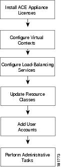
Configuration Overview
Use the flow chart in Figure 1-7 to get started with the ACE Appliance Device Manager. Table 1-8 describes these tasks in more detail.
Figure 1-7 High-Level Configuration Process
|
|
|
|
|---|---|---|
In this step you install licenses for ACE appliances that let you increase the number of virtual contexts, appliance bandwidth, and SSL TPS (transactions per second). See Managing ACE Appliance Licenses for details. |
||
In this step you partition the ACE appliance into multiple virtual devices or contexts . Each context contains its own set of policies, interfaces, resources, and administrators, allowing you to efficiently manage resources, users, and the services you provide to your customers. See Using Virtual Contexts for details. |
||
In this step you configure load balancing to manage client requests for service. See Load Balancing Overview for details. |
||
In this step you configure resource usage models that you can apply across your network. See Managing Resource Classes for details. |
||
In this step you set up tiered access for users. See Managing the ACE Appliance for details. |
||
This step includes ongoing maintenance and administrative tasks, such as follows:
|
Understanding ACE Features
The ACE performs high-performance server load balancing (SLB) among groups of servers, server farms, firewalls, and other network devices, based on Layer 3 as well as Layer 4 through Layer 7 packet information. The ACE provides the following major features and functionality.
- Ethernet Interfaces—The ACE provides four physical Ethernet ports that provide an interface for connecting to 10-Mbps, 100-Mbps, or 1000-Mbps networks. Each Layer 2 Ethernet port supports autonegotiate, full-duplex, or half-duplex operation on an Ethernet LAN, and can carry traffic within a designated VLAN interface.
- Routing and Bridging—You configure the corresponding VLAN interfaces on the ACE as either routed or bridged. When you configure an IP address on an interface, the ACE automatically configures it as a routed mode interface. When you configure a bridge group on an interface VLAN, the ACE automatically configures it as a bridged interface.
- Traffic Policies—The ACE allows you to perform advanced administration tasks such as using traffic policies to classify traffic flow and the action to take for the type of traffic. Traffic policies consist of class maps, policy maps, and service policies.
- Redundancy—Redundancy provides fault tolerance for the stateful switchover of flow, and offers increased uptime for a more robust network.
- Virtualization—Virtualization allow you to manage ACE system resources and users, as well as the services provided to your customers. Multiple contexts use the concept of virtualization to partition your ACE into multiple virtual devices or contexts. Each context contains its own set of policies, interfaces, resources, and administrators.
- Server Load Balancing— Server load balancing (SLB) on the ACE provides network traffic policies for SLB, real servers and server farms, health monitoring through probes, and firewall load balancing.
- ACE Security Features—The ACE contains several security features including ACLs, NAT, user authentication and accounting, HTTP deep packet inspection, FTP command request inspection, and application protocol inspection of DNS, HTTP, ICMP, or RTSP.
- Secure Sockets Layer—The SSL protocol on the ACE provides encryption technology for the Internet, ensuring secure transactions.
- Application Acceleration and Optimization—The ACE includes several optimization technologies to accelerate Web application performance, optimize network performance, and improve access to critical business information.
- Command-Line Interface—The command-line interface (CLI) is a line-oriented user interface that provides commands for configuring, managing, and monitoring the ACE. For more information, see the Command Reference, Cisco ACE Application Control Engine .
- ACE Appliance Device Manager Overview
- Command Reference, Cisco ACE Application Control Engine
IPv6 Considerations
The DM supports IPv6 configurations with the following considerations:
- By default, IPv6 is disabled on an interface. You must enable IPv6 on the interface to enable its configured IPv6 addresses. The interface cannot be in bridged mode. The interface may or may not have IPv4 addresses configured on it.
- When you enable IPv6 or configure a global IPv6 address on an interface, the ACE automatically does the following:
–![]() Configures a link-local address (if it is not already configured)
Configures a link-local address (if it is not already configured)
–![]() Performs duplicate address detection (DAD) on both addresses
Performs duplicate address detection (DAD) on both addresses
You must enable IPv6 on the interface to enable global IPv6 address.
- IPv6 on interface can be individually enabled or disabled. IPv6 cannot be enable or disable globally.
- A link-local address is an IPv6 unicast address that has a scope of the local link only and is required on every interface. Every link-local address has a predefined prefix of FE80::/10. You can configure a link-local address manually. If you do not configure a link-local address before enabling an IPV6 address on the interface, the ACE automatically generates a link-local address with a prefix of FE80::/64. Only one IPv6 link-local address can be configured on an interface.
In a redundant configuration, you can configure an IPv6 peer link-local address for the standby ACE. You can configure only one peer link-local address on an interface.
- A unique-local address is an optional IPv6 unicast address that is used for local communication within an organization and it is similar to a private IPv4 address (for example, 10.10.2.1). unique-local addresses have a global scope, but they are not routable on the internet, and they are assigned by a central authority. All unique-local addresses have a predefined prefix of FC00::/7. You can configure only one IPv6 unique-local address on an interface.
In a redundant configuration, you can configure an IPv6 peer unique-local address on the active that is synchronized to the standby ACE. You can configure only one peer unique-local IPv6 address on an interface.
- A global address is an IPv6 unicast address that is used for general IPv6 communication. Each global address is unique across the entire Internet. Therefore, its scope is global. The low order 64 bits can be assigned in several ways, including autoconfiguration using the EUI-64 format. You can configure only one globally unique IPv6 address on an interface.
In a redundant configuration, you can configure an IPv6 peer global address that is synchronized to the standby ACE.
When you configure redundancy with active and standby ACEs, you can configure a VLAN interface that has an alias global IPv6 address that is shared between the active and standby ACEs. The alias IPv6 address serves as a shared gateway for the two ACEs in a redundant configuration. You can configure only one alias global IPv6 address on an interface.
- A multicast address is used for communications from one source to many destinations. IPv6 multicast addresses function in a manner that is similar to IPv4 multicast addresses. All multicast addresses have a predefined prefix of FF00::/8.
- The ACE supports abbreviated IPv6 addresses. When using double colons (::) for leading zeros in a contiguous block, they can only be used once in an address. Leading zeros can be omitted. Trailing zeros cannot be omitted. The DM will abbreviate an IPv6 address after you finish typing it. If you enter the entire address with a block of contiguous zeros, the DM collapses it into the double colons. For example: FF01:0000:0000:0000:0000:0000:0000:101 becomes FF01::101.
- The ACE uses the Neighbor Discovery (ND) protocol to manage and learn the mapping of IPv6 to Media Access Control (MAC) addresses of nodes attached to the local link. The ACE uses this information to forward and transmit IPv6 packets. The neighbor discovery protocol enables IPv6 nodes and routers to:
–![]() Determine the link-layer address of a neighbor on the same link
Determine the link-layer address of a neighbor on the same link
The IPv6 neighbor discovery process uses ICMPv6 messages and solicited-node multicast addresses to determine the link-layer address of a neighbor on the same network (local link), verify the reachability of a neighbor, and keep track of neighbor routers. The IPv6 neighbor discovery process uses the following mechanisms for its operation:
- The ACE supports IPv6-to-IPv6 L4/L7 SLB, including support for IPv6 VIP, predictor, probe, server farm, sticky, access-list, object-group, interface, source NAT, OCSP, and CRL.
- The probe must have the same IP address type (IPv6 or IPv4) as the real server. For example, you cannot configure an IPv6 probe to an IPv4 real server.
- You can associate both IPv6 and IPv4 probes to a server farm.
- Only the following Layer 7 protocol will support IPv6:
–![]() IPv6-to-IPv4 SLB and IPv4-to-IPv6 SLB for L7 HTTP/HTTP/TCP/UDP
IPv6-to-IPv4 SLB and IPv4-to-IPv6 SLB for L7 HTTP/HTTP/TCP/UDP
–![]() IPv6 access-list and object group
IPv6 access-list and object group
- ICMPv6 traffic is not automatically allowed. You must configure the corresponding management traffic policy to allow the ping request to ACE. However, the necessary ND (neighbor Discovery) messages for ARP, duplication address detection are automatically permitted.
- All the management traffic used by the network management server or DM is required to send over IPv4 protocol. IPv6 is not supported.
- Copying files over IPv6 to or from devices are not supported.
- The ACE supports IPv6 HA:
Understanding ACE Appliance Device Manager Terminology
It is useful to understand the following terms when using the ACE Appliance Device Manager:
A virtual context is a concept that allows users to partition an ACE appliance into multiple virtual devices. Each virtual context contains its own set of policies, interfaces, and resources, allowing administrators to more efficiently manage system resources and services.
In a load-balancing environment, a virtual server is a construct that allows multiple physical servers to appear as one for load-balancing purposes. A virtual server is bound to physical services running on real servers in a server farm and uses IP address and port information to distribute incoming client requests to the servers in the server farm according to a specified load-balancing algorithm.
Managing users using role-based access allows administrators to set up users, roles, and domain access to your virtual contexts. Each user is assigned a role and a domain which defines what virtual contexts they can view and configure. Roles determine which commands and resources are available to a user. Domains determine which objects they can use. Only users associated with an admin virtual context are allowed to see other virtual contexts.
There are two types of virtual contexts:
The Admin context, which contains the basic settings for each virtual device or context, allows a user to configure and manage all contexts. When a user logs into the Admin context, he or she has full system administrator access to the entire ACE appliance and all contexts and objects within it. The Admin context provides access to network-wide resources, for example, a syslog server or context configuration server. All global commands for ACE appliance settings, contexts, resource classes, and so on, are available only in the Admin context.
A user context has access to the resources in which the context was created. For example, a user context that was created by an administrator while in the Admin context, by default, has access to all resources in an ACE appliance. Any user created by someone in a user-defined context only has access to the resources within that context. In addition, roles and domains create access parameters for each user. For a description of the predefined user roles, see Managing User Roles.
For more information on RBAC, see Controlling Access to the Cisco ACE Appliance.
A resource class is a defined set of resources and allocations available for use by a virtual context. Using resource classes prevents a single context from using all available resources and can be used to ensure that every context is guaranteed the minimum set of resources necessary.
- Controlling Access to the Cisco ACE Appliance
- ACE Appliance Device Manager Interface Overview
- Conventions in Tables
Supported Browsers for ACE Appliance Device Manager
The ACE appliance Device Manager is supported on the following browsers listed in Table 9 . All browsers require cookies and DHTML (JavaScript) to be enabled.
 Feedback