Configuring Virtual Access Points (VAPs) on the WAP121 and WAP321
Available Languages
Objective
Virtual Access Points (VAPs) simulate multiple access avenues in one physical WAP device. VAPs are similar to Ethernet Virtual Local Area Networks (VLANs). Each VAP can be enabled or disabled independently and is identified by a user-configured Service Set Identifier (SSID) or also known as Network Names. You can configure up to four VAPs on the Cisco WAP121 and up to eight VAPs on the Cisco WAP321.
The objective of this document is to show you how to configure Virtual Access Points on the Cisco WAP121 and WAP321 Access Points.
Applicable Devices
- WAP121
- WAP321
Software Version
- 1.0.6.5
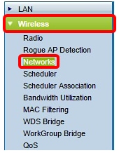
Step 1. Log in to the Access Point web-based utility and choose Wireless > Networks.
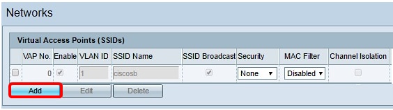
Step 2. Under the Virtual Access Points (SSIDs) table, click the Add button.
Note: VAP No. 0 is the default physical radio interface and can be modified depending on your preference. This VAP cannot be deleted and remains enabled as long as the radio is enabled.
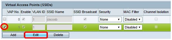
Step 3. Check the check box beside the VAP number then click Edit.
Step 4. In the VLAN ID field, enter the VLAN ID where you want to associate the VAP that you are creating. A VLAN ID can be any value from 1 to 4094.
Note: Verify that the VLAN ID is properly configured on the network. Network errors may arise if the VAP communicates with wireless clients on an improperly configured VLAN. The WAP121 supports five active VLANs (four WLAN plus one management VLAN), and the WAP321 supports nine active VLANs (eight WLAN plus one management VLAN).
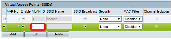
Note: In this example, VLAN ID 1 is used. This is the default setting.
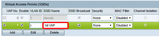
Step 5. In the SSID Name field, create a name for the VAP. The SSID can contain any case-sensitive, alphanumeric entry between 2 to 32 characters.
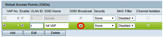
Step 6. Check the SSID Broadcast check box. This will allow your VAP to be visible to any wireless device within its range.
Note: The SSID Broadcast is enabled by default. Disabling SSID broadcast prevents wireless clients from connecting to the network since the VAP will not be visible, however, it only offers minimal level of protection and does not prevent security threats to connect or monitor unencrypted traffic. SSID broadcasts can be independently enabled or disabled on each VAP.
Step 7. Choose an option from the Security drop-down list depending on what type of security you prefer to use on the VAP. The options are:
- None — Open or no security. This is the default option. If this option is chosen, skip to Step 10.
- WPA Personal — More advanced security in comparison to WEP, and can support keys of length 8-63 characters.
- WPA Enterprise — The most advanced method of security. It uses Protected Extensible Authentication Protocol (PEAP) in which every wireless user under WAP is authorized with individual usernames and passwords. These passwords can support Advanced Encryption Standard (AES). It also uses Transport Layer Security (TLS) in addition to PEAP, in which every user also needs to provide an additional certificate to gain access.
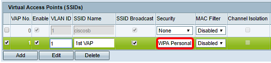
Note: In this example, WPA Personal is chosen.
Step 8. In the Key field, create a password for the VAP. This will be the password that each wireless client would need to enter to connect to the wireless network.
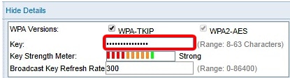
Note: The Key Strength Meter would indicate the strength of the password that you have created.
Step 9. Enter a value in the Broadcast Key Refresh Rate. This will be the interval at which the broadcast (group) key is refreshed for clients associated with this VAP. The valid range is from 0 to 86400 seconds.
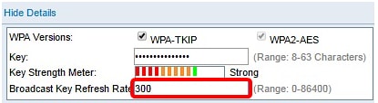
Note: In this example, the default value 300 is used.
Step 10. Choose an option from the MAC Filter drop-down list to specify whether the clients that can access the VAP are restricted to a configured global list of MAC addresses. The options are:
- Disabled — All clients can access the upstream network.
- Locale — The set of clients that can access the upstream network is restricted to the clients specified in a locally defined MAC address list.
- Radius — The set of clients that can access the upstream network is restricted to the clients specified in a MAC address list on a RADIUS server.
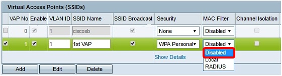
Note: In this example, the default setting Disabled is chosen.
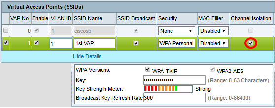
Step 11. (Optional) Check the Channel Isolation check box if you want the WAP device to block communication between the wireless clients on the same VAP. The WAP device still allows data traffic between its wireless clients and the wired devices on the network, across a WDS link, and with other wireless clients associated with a different VAP, but not among the wireless clients.
Step 12. Repeat Steps 2 to 11 for every VAP you want to add. You can configure up to four VAPs on the Cisco WAP121 and up to eight VAPs on the Cisco WAP321.
Step 13. Click the  button.
You should now have successfully configured Virtual Access Points to your WAP121 and WAP321 Access Points.
Revision History
| Revision | Publish Date | Comments |
|---|---|---|
1.0 |
11-Dec-2018 |
Initial Release |
 Feedback