Denial of Service (DoS) IP Fragments Filtering Configuration on Sx500 Series Stackable Switches
Available Languages
Objective
Denial of Service (DoS) Prevention increases network security and filters packets with certain IP address parameters so that they do not enter into the network. The maximum size of the IP packet is 1500 bytes by default, but when the packet exceeds this size the packet needs to fragmented. These packets need to be blocked at times because they can pose some security vulnerabilities like too many incomplete datagrams can be created to cause denial of service and can attempt to bypass security measures.
The DoS IP fragments filtering is used to block the fragmented IP packets. This document explains how to configure the DoS IP fragments filtering settings on the Sx500 Series Stackable Switches.
Applicable Devices
• Sx500 Series Stackable Switches
Software Version
• v1.2.7.76
Add IP Fragments Filter
Step 1. Log in to the web configuration utility and choose Security > Denial Of Service Prevention > IP Fragments Filtering. The IP Fragments Filtering page opens:
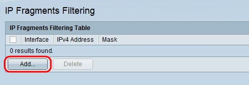
Step 2. In the IP Fragments Filtering Table click Add. The Add IP Fragments Filtering window appears.
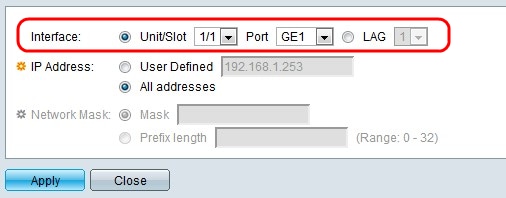
Step 3. Click the radio button that corresponds to the desired interface type in the Interface field.
• Unit/Slot — From the Unit/Slot drop-down lists choose the appropriate Unit/Slot. The unit identifies whether the switch is active or a member in the stack. The slot identifies which switch is connected to which slot (slot 1 is SF500 and slot 2 is SG500). If you are unfamiliar with the terms used, check out Cisco Business: Glossary of New Terms.
– Port — From the Port drop-down list, choose the appropriate port to configure.
• LAG — Choose the desired LAG from the LAG drop-down list. A Link Aggregate Group (LAG) is used to link multiple ports together. LAGs multiply bandwidth, increase port flexibility, and provide link redundancy between two devices to optimize port usage.
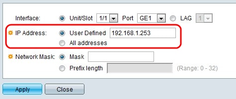
Step 4. Click the radio button that corresponds with the IP address from which packets are to be filtered in the IP Address field.
• User Defined — Enter an IP address from which the fragmented IP packets are filtered.
• All Addresses — Blocks fragmented IP packets from all addresses.
Note: If you chose All Addresses in Step 4, skip to Step 6.
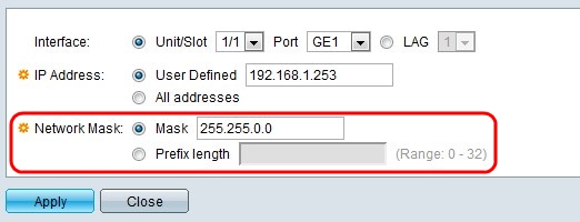
Step 5. Click the radio button that corresponds with the desired network mask in the Network Mask field.
• Mask — Enter the network mask in IP address format. This defines the subnet mask for the IP address.
• Prefix length — Enter the prefix length (integer in the range of 0 to 32). This defines the subnet mask by prefix length for the IP address.
Step 6. Click Apply.
 Feedback