Management Access Method Profile Rules Configuration on Sx500 Series Stackable Switches
Available Languages
Objective
Access profiles act as another layer of security for the switch. Access profiles can contain up to 128 rules to increase security. Each rule contains an action and a criteria. If the incoming packet matches the rule and the access method matches the management method, the action is performed. If the packet does not match a rule in the access profile, the packet is dropped. If the access method does not match the management method, the switch generates a SYSLOG message to notify the network administrator of the failed attempt.
This article explains how to configure profile rules on the Sx500 Series Stackable Switches.
Note: To configure access profile rules you need to configure access profiles refer to Management Access Authentication Setup on Sx500 Series Switches.
Applicable Devices
• Sx500 Series Stackable Switches
Software Version
• 1.3.0.62
Profile Rules
Step 1. Log in to the web configuration utility and choose Security > Mgmt Access Method > Profile Rules. The Profile Rules page opens:
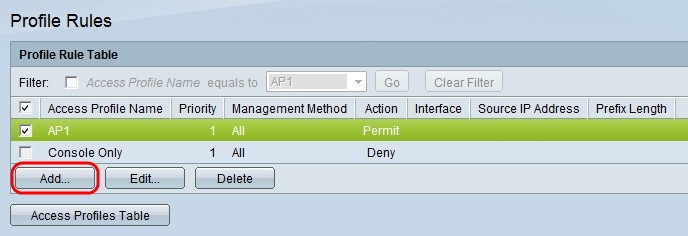
Step 2. Check the check box that corresponds to the desired Access Profile Name and click Add to add a new profile rule. The Add Profile Rule window appears.
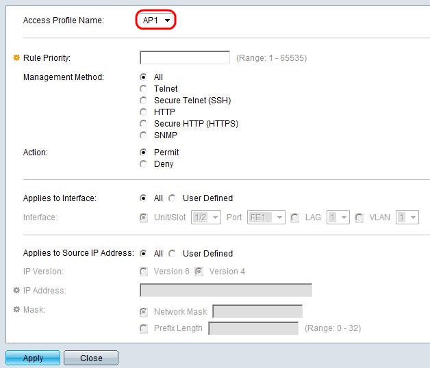
Step 3. (Optional) From the Access Profile Name drop-down list choose the access profile to which you would like to add a rule.
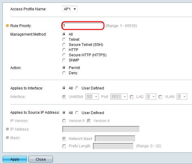
Step 4. Enter a value for the rule priority in the Rule Priority field. The rule priority matches packets with rules. Rules with lower priority are checked first. If a packet matches a rule the desired action is performed.
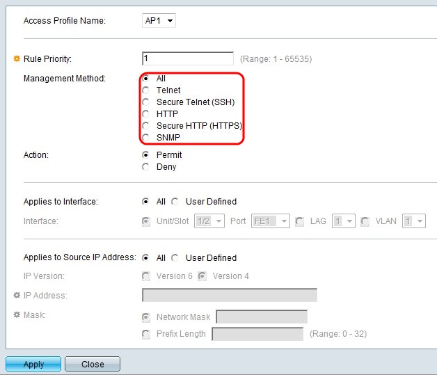
Step 5. Click the radio button that corresponds to the desired management method in the Management Method field. The access method used by the user must match the management method in order for the action to be performed.
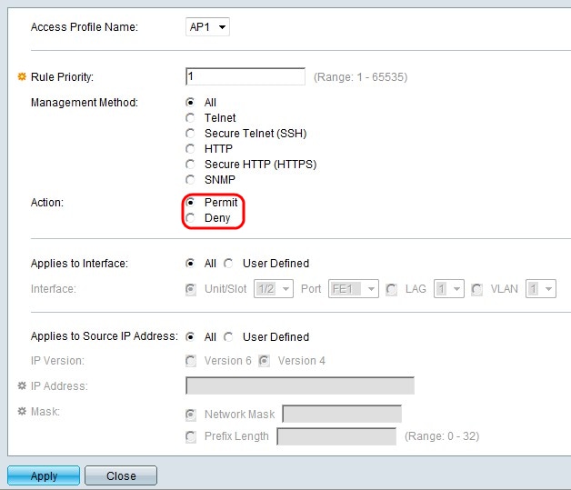
Step 6. Click the radio button that corresponds to the desired action in the Action field.
• Permit — Permits the user to access the switch through the access method chosen in step 5.
• Deny — Denies the user access to the switch through the access method chosen in step 5.
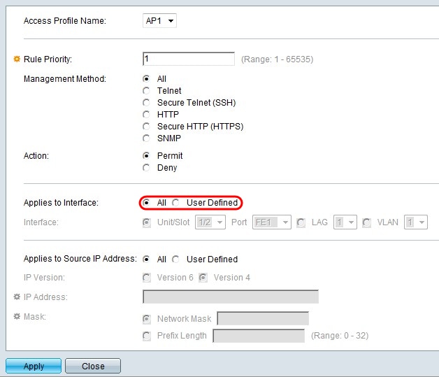
Step 7. Click the radio button that corresponds to the desired interface in the Applies to Interface field.
• All — Applies to all ports, LAGs, and VLANs on the switch the above step 5 and step 6 rule.
• User Defined — Applies only to the chosen port, LAG, or VLAN on the switch the above step 5 and step 6 rule.
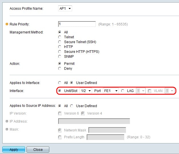
Step 8. If User Defined is chosen in the previous step, click the radio button that corresponds to the desired interface in the Interface field. Choose a port from the Unit/Slot and Port drop-down lists, a LAG from the LAG drop-down list, or a VLAN from the VLAN drop-down list accordingly.

Step 9. Click the radio button that corresponds to the desired IP address in the Applies to Source IP Address field.
• All — Applies to all types of IP addresses.
• User Defined — Only applies to the type of IP address that is defined in here to allow or deny from the above rules.
Timesaver: If All is chosen in step 9 skip to step 13.
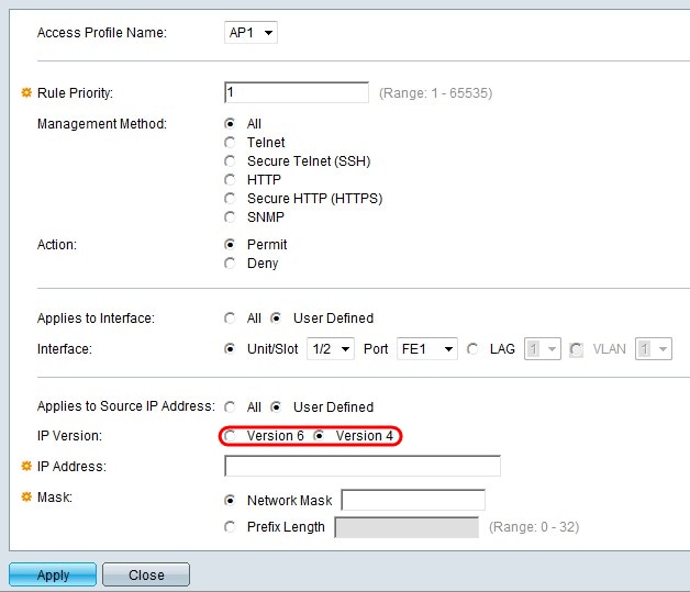
Step 10. If User Defined is chosen, click the radio button that corresponds to the supported IP version in the IP Version field.
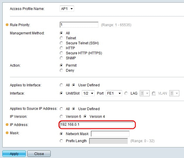
Step 11. Enter the source IP address in the IP Address field.
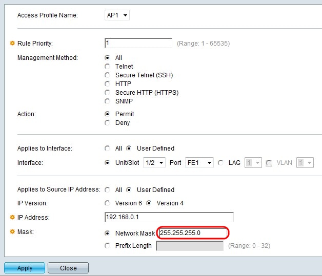
Step 12. Click the radio button that corresponds to the network mask in the Mask field.
• Network Mask — Enter the network mask in the Network Mask field. This will define the subnet mask for the source IP address.
• Prefix Length — Enter the prefix length (integer in the range of 0 to 32) in the Prefix length field. This will define the subnet mask by prefix length for the source IP address.
Step 13. Click Apply.
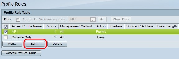
Step 14. (Optional) To edit the profile rules, check the desired access profile check box and click Edit.
Step 15. (Optional) To delete the access profile rule from the profile rule table, check the desired access profile check box and click Delete.
Revision History
| Revision | Publish Date | Comments |
|---|---|---|
1.0 |
13-Dec-2018 |
Initial Release |
 Feedback