IPv6-Based ACL & ACE on 300 Series Managed Switches
Available Languages
Objective
This article explains how to create an IPv6-Based ACL & ACE on 300 Series Managed Switches. It can permit or deny the entry of packets to the IP addresses configured on the access list. The rules for the ACL are given by the Access Control Entries (ACEs).
Applicable Devices
- 300 Series Managed Switches
Configuration of IPv6-Based ACL and ACE
IPv6-Based ACL
Step 1. Use the Configuration Utility to choose Access Control > IPv6-Based ACL. The IPv6-Based ACL page opens. This page will display the list of ACLs which are defined currently.
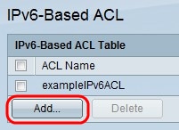
Step 2. Click Add to add a new access list.
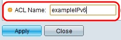
Step 3. Enter a name for the access list in the ACL Name field.
Step 4. Click Apply which causes the IPv6-Based ACL to be written to the running configuration file.
IPv6-Based ACE Configuration
To add an Access Control Entry (ACE) to the ACL, perform the following steps:
Step 1. Use the Configuration Utility to choose Access Control > IPv6- Based ACE. The IPv6-Based ACE page opens:
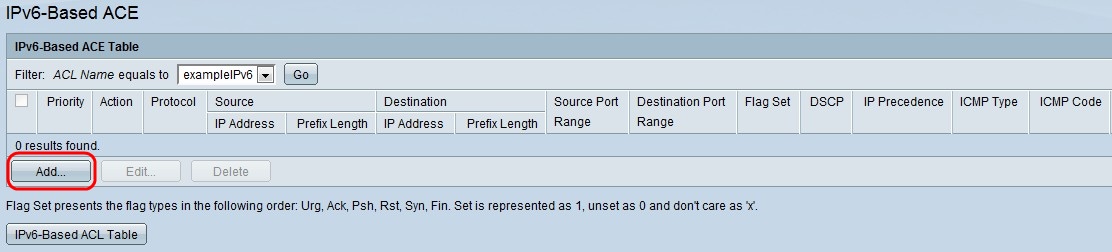
Step 2. Choose an ACL from the ACL Name equals to drop-down list and click Add. The Add IPv6-based ACE window appears.


Step 3. Enter the priority of the ACEs in the Priority field. The highest priority are processed first which is 1. It has a range of 1 - 2147483647.
Step 4. Click the radio button corresponding to the desired action that occurs when the packet is a match in the Action field.
- Permit — Allows packets that match the ACE criteria.
- Deny — Drops packets that meet the ACE criteria.
- Shutdown — Drops packets that meet the ACE criteria and disables the port from where the packets were received. Such ports can be reactivated from the port settings page.
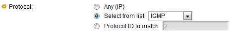
Step 5. Click the radio button corresponding to the desired protocol for the ACE, which are configured for all routed network protocols in order to filter the packets as this packets pass through a router.
- Any — It will choose any of the IPv6-based ACE protocol.
- Select from list — Choose any of the protocols from the drop-down list (TCP, UDP, ICMP).
- Protocol ID to match — It is used to match the protocol with a ID. The default value for different protocol like TCP it is 6, UDP it is 17 and for ICMP it is 58 or the user can define any value in it.
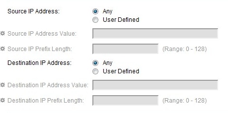
Step 6. Click Any if all the source addresses are acceptable or User Define if a Source IP address value with its prefix length have to be entered in the Source IP Address field.
Step 7. Click Any if all the destination addresses are acceptable or User Defined if a destination IP address value with its prefix length have to be entered in the Destination IP Address field.
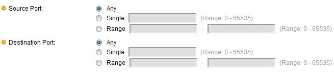
Step 8. Source Port are enabled only when you choose protocol TCP & UDP from Step 5. Click Any if all the Source Port are acceptable or Single value from the given range 0 - 65535 or a Range of Source Port have to be entered.
Step 9. Destination Port are enabled only when you choose protocol TCP & UDP from Step 5. Click Any if all the Source Port are acceptable or Single value from the given range 0 - 65535 or a Range of Destination Port have to be entered.
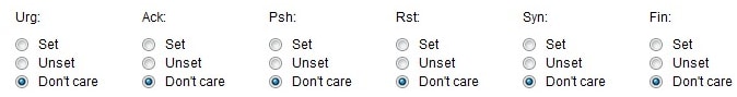
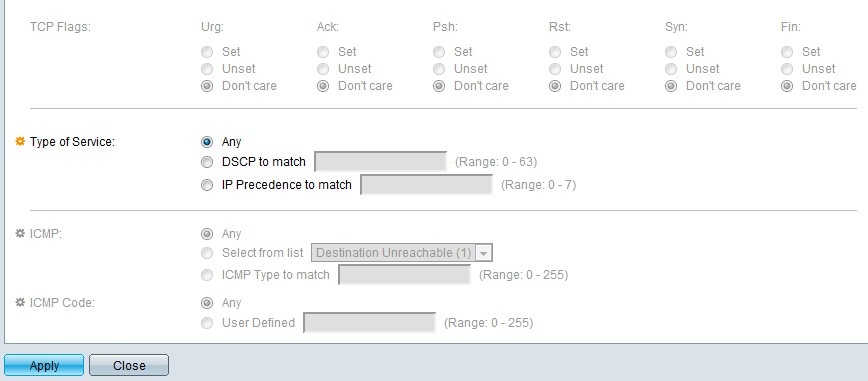
Step 10. TCP Flags are enabled only when you choose protocol TCP from Step 5. Click any of the flags with different options as Set as 1 or on, Unset as 0 or off or Don't care as x.
- Urg — This flag is used to identify incoming data as Urgent.
- Ack — This flag is used to acknowledge the successful receipt of packets.
- Psh — This flag is used to ensure that the data is given the priority (that it deserves) and is processed at the sending or receiving end.
- Rst — This flag is used when a segment arrives that is not intended for the current connection.
- Syn — This flag is used for TCP communications.
- Fin — This flag is used when the communication or data transfer is Finished.
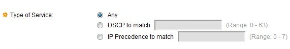
Step 11. Click the radio button corresponding to the desired service type for traffic congestion control in the Type of Service field.
- Any — Any type of service is used for traffic congestion.
- DSCP to match — Differentiated Service Code Point (DSCP) is a mechanism for classifying and managing network traffic. Six bits(0-63) is used to select the Per Hop Behaviour a packet experiences at each node.
- IP Precedence to match — To set a preference type for IPv6 packets. The keyword with IP Preference value are 0 for routine, 1 for priority, 2 for immediate, 3 for flash, 4 for flash-override, 5 for critical, 6 for internet, 7 for network.
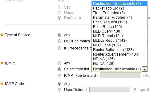
Step 12. ICMP is enabled only when you choose protocol ICMP in Step 11. It is used to send a error messages when service not available or a host or a router could not be reached. It is also used for relay query messages.
- Any — It can be any of the error message or query message.
- Select from list — It has a drop down list of permitted control messages as follows
– Destination Unreachable — It is generated by the host or its gateway to inform the client that the destination is unreachable for some reason (Network or Host unreachable error and so on ).
– Packet Too Big — The size of the Datagram is exceeded than the given MTU.
– Time Exceeded — It is generated by a gateway to inform the source of a discarded datagram due to the time to live field reaching zero.
– Parameter Problem — It is generated as a response for any error not specifically covered by another ICMP message.
– Echo Request — It is a ping, whose data is expected to be received back in an echo reply.
– Echo Reply — It is generated in response to an echo request.
– MLD Query — It is used to learn which multicast addresses have listeners on an attached link. Type 130 in decimal.
– MLD Report — It is generated when IPv6 multicast address to which the message sender is listening
– MLD V2 Report — It is same as MLD Report with version 2.
– MLD Done — when the host leaves a group, it sends a multicast listener done message to multicast routers on the network
– Router Solicitation — It is a router discovery message. Hosts discover the addresses of their neighboring routers simply by listening for advertisements. Default = 224.0.0.2 for multicast, otherwise 255.255.255.255.
– Router Advertisement — The router periodically multicasts a Router Advertisement from each of its multicast interfaces, announcing the IP addresses of that interface.
– ND NS — Messages are originated by nodes to request another node's link layer address and also for functions such as duplicate address detection and neighbor unreachability detection
– ND NA — Messages are sent in response to NS messages. If a node changes its link-layer address, it can send an unsolicited NA to advertise the new address
Step 13. ICMP Code is enabled only when you choose protocol ICMP from Step 11. It is used to provides more specific information of the control messages with a value.
- ICMP type to match — The user has to enter a range between 0-255 to match the ICMP control messages.
- Any — It can be any value that match the control message.
- User Defined — The value is defined from the range between the 0-255, to match the control messages.
Step 14 . Click Apply which writes the IPv6-Based ACE to the running configuration file.
Revision History
| Revision | Publish Date | Comments |
|---|---|---|
1.0 |
10-Dec-2018
|
Initial Release |
 Feedback