Link Layer Discovery Protocol Properties Configuration on 200/300 Series Managed Switches
Available Languages
Objectives
The main functions of Link Layer Discovery Protocol (LLDP) are to make sure that network devices installed on a given network advertise themselves properly to its neighbors and to enable the device to store discovery information about its neighbors. This protocol is useful for troubleshooting purposes. The 300 Series Managed Switches offers different LLDP properties you can manually configure. In this way, you can have more accurate information about the different events in your network so that you can more quickly detect a possible connectivity problem. This article explains how to configure the LLDP properties on the 200/300 Series Managed Switches.
Applicable Devices
• SF/SG 200 and SF/SG 300 Series Managed Switches
Software Version
• 1.3.0.62
LLDP Properties Setup
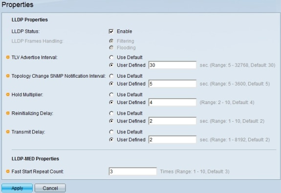
Step 1. Log in to the web configuration utility and choose Administration > Discovery - LLDP > Properties. The Properties page opens:

Step 2. Check the Enable check box to enable LLDP on the switch in the LLDP Status field.
Note: If LLDP is not enabled, click the radio button for the action you wish to be taken if a packet that matches the chosen criteria is received:
• Filtering — Deletes the packet.
• Flooding — Forwards the packet to all VLAN members.
Step 3. The TLV Advertise Interval field sets the rate in seconds at which LLDP advertisement updates are sent. Click the radio button of one of the available options to set the parameter:
• Use Default — A default value for this parameter is used.
• User Defined — A defined value for this parameter can be entered in the given field.
Step 4. The Topology Change SNMP Notification Interval field sets the minimum time interval in seconds for notifications when the topology of the switch changes. Click the radio button of one of the available options to set this parameter:
• Use Default — A default value for this parameter is used.
• User Defined — A defined value for this parameter can be entered in the given field.
Step 5. The Hold Multiplier field sets the amount of time that LLDP packets are held before the packets are discarded. This unit is measured in multiples of the TLV Advertise Interval. For Example, if the TLV Advertise Interval is 20 seconds and the Hold Multiplier is 4, the LLDP packets will be discarded after 80 seconds. Click the radio button for one of the available options to set this parameter:
• Use Default — A default value for this parameter is used.
• User Defined — A defined value for this parameter can be entered in the given field.
Step 6. The Reinitializing Delay field sets the time interval in seconds that passes between disabling and reinitializing LLDP. This event follows an LLDP enable/disable cycle. Click the radio button of one of the available options to set this parameter:
• Use Default — A default value for this parameter is used.
• User Defined — A defined value for this parameter can be entered in the given field.
Step 7. The Transmit Delay field sets amount of time in seconds that passes between successive LLDP frame transmissions. This is due to changes in the LLDP local systems management information base. Click the radio button of one of the available options to set this parameter:
• Use Default — A default value for this parameter is used.
• User Defined — A defined value for this parameter can be entered in the given field.
Step 8. The Fast Start Repeat Count field sets the number of times LLDP packets are sent when the LLDP-MED Fast Start mechanism is initialized. This event occurs when a new media endpoint device links to the switch. Enter in this field the desired number of times.
Step 9. Click Apply to save configuration.
Revision History
| Revision | Publish Date | Comments |
|---|---|---|
1.0 |
10-Dec-2018
|
Initial Release |
 Feedback