Calculating the Maximum Hop Distances for 15454 Fiber Links
Available Languages
Contents
Introduction
This document describes how to calculate the maximum hop distance for an optical fiber and, in particular, for the Cisco ONS 15454. You can apply this methodology to all types of optical fibers in order to estimate the maximum distance that optical systems use.
Prerequisites
Requirements
There are no specific requirements for this document.
Components Used
This document is not restricted to specific software and hardware versions.
The information in this document was created from the devices in a specific lab environment. All of the devices used in this document started with a cleared (default) configuration. If your network is live, make sure that you understand the potential impact of any command.
Conventions
Refer to Cisco Technical Tips Conventions for more information on document conventions.
What Is Attenuation?
This section explains the meaning of attenuation, and provides guidelines to calculate the maximum distance for optical links on the basis of different wavelengths.
Attenuation is a measure of the loss of signal strength or light power that occurs as light pulses propagate through a run of multimode or single-mode fiber. Measurements are typically defined in terms of decibels or dB/km.
Wavelength
The most common peak wavelengths are 780 nm, 850 nm, 1310 nm, 1550 nm, and 1625 nm. The 850 nm region, referred to as the first window, was used initially because this region supported the original LED and detector technology. Today, the 1310 nm region is popular because of the dramatically lower loss and lower dispersion.
The 1550 nm region also is used today, and can avoid the need for repeaters. Generally, performance and cost increase as wavelength increases.
Multimode and single-mode fiber use different fiber types or sizes. For example, single-mode fiber uses 9/125 um and multimode uses 62.5/125 or 50/125. The different size fibers have different optical loss dB/km values. Fiber loss depends heavily on the operating wavelength. Practical fibers have the lowest loss at 1550 nm and the highest loss at 780 nm with all physical fiber sizes (for example, 9/125 or 62.5/125).
When you calculate the maximum distance for any optical link, consider the details provided in table 1 and table 2:
Table 1 – For Wavelength 1310nm| Attenuation/ km (dB/km) | Attenuation/optical connector (dB) | Attenuation/joint (dB) | Conditions | |
|---|---|---|---|---|
| Min | 0.30 | 0.40 | 0.02 | Best conditions |
| Average | 0.38 | 0.60 | 0.10 | Normal |
| Max | 0.50 | 1.00 | 0.20 | Worst situation |
| Attenuation/ km (dB/km) | Attenuation/optical connector (dB) | Attenuation/joint (dB) | Conditions | |
|---|---|---|---|---|
| Min | 0.17 | 0.20 | 0.01 | Best conditions |
| Average | 0.22 | 0.35 | 0.05 | Normal |
| Max | 0.04 | 0.70 | 0.10 | Worst situation |
Here is an example of a typical situation in the field:
| Card | Fiber Light Levels | |
|---|---|---|
| Rx Level Max - Min | Tx Level Max - Min | |
| OC3 | -8 to -28 | -8 to -15 |
| OC12 | -8 to -28 | -8 to -15 |
| OC12 | -8 to -28 | +2 to -3 |
| OC12 | -8 to -28 | +2 to -3 |
| OC48 | 0 to -18 | 0 to -5 |
| OC48 | -8 to -28 | +3 to -2 |
| OC48 | -8 to -28 | 0 to -2 |
| Tx/Rx | Max | Min |
|---|---|---|
| Transmitter (Tx) Output Power: | Max. +10 dBm | Min. +7 dBm |
| Receiver (Rx) Level: | Max. -10 dBm | Min: -19 dBm |
For this card, the power budget is between: 29dB and 17 dB.
Calculate the Maximum Hop
With the information provided in the What Is Attenuation? section, you can calculate all the attenuation for any span, including the maximum hop distance for the Cisco ONS 15454.
Optical Budget Loss Equation
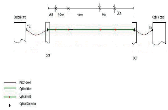
Atotal = (wavelength λ loss dB/km x fibre length) + (connector loss x number of connectors) + (splice loss x number of splices).
Kilometer to Mile Conversion
Km x .6214 = miles (1mile = 1.60km)
Here is an example to calculate the maximum hop distance for the OC48 LR 1550 card. For this card:
-
Min Rx level is -28dB and Min Tx level is -2dB
-
Max Rx level is -8dB and Max Tx level is +3dB
For this card, the power budget is between: 31dB and 6 dB.
Given that the maximum Rx level is -8dB, this means that if the laser power source is "hotter", the board can suffer damage. Also, because the Min Rx level = -28dB, you cannot receive beyond this limit.
With this in mind, assume that:
-
The minimum attenuation on line must be at least:
A(min) = Max Tx level - Max Rx level = +3dB - (- 8dB) = 11dB
-
The maximum attenuation on line must be:
A(max) = Min Tx level - Min Rx level = -2dB - (- 28dB) = 26dB
You also need to take a system margin into consideration. Patch cords, cable bend, unpredictable optical attenuation events, and so on, require around 3dB. In addition, a number of splices in elementary cable section some external connectors (you can have at least two at of possibly 0.7dB so you can consider this to be around 1.5 dB).
On the basis of this information, you can estimate that the new values for calculation are:
A(min) = 11dB - 4.5dB = 6.5dB
A(max) = 26dB - 4.5dB = 21.5dB
With these results, you can conclude that the maximum attenuation for optical cable (TA) must be maximum 26dB for one link with OC48 LR 1550, and cannot be less than 11 dB.
This takes these conditions into account:
-
The minimum length for the optical fiber on a cable is:
L(min) = A(min) / a= 6.5dB/ 0.22dB/km = 29.5km
-
The maximum length for the optical fiber on a cable is:
L(max) = A(max) / a = 21.5dB/ 0.22dB/km = 97.72km
where, a = attenuation for the optical cable (dB/km).
On the basis of this calculation, the maximum hop distance for the OC48 LR 1550 card is between 29.5km and 97.72km.
With this procedure as a basis, you can now calculate all others spans.
Related Information
 Feedback
Contact Cisco
- Open a Support Case

- (Requires a Cisco Service Contract)