Collapse Multiple STP Instances into a Single STP Instance with E-Series Ethernet on ONS 15454
Available Languages
Contents
Introduction
This document describes the procedure to collapse multiple Spanning Tree Protocol (STP) instances into a single STP instance in order to overcome the limitation of eight STP instances for every 15454 node.
Prerequisites
Requirements
Cisco recommends that you have knowledge of these topics:
-
Cisco ONS 15454
-
Spanning Tree Protocol
Components Used
The information in this document is based on these software and hardware versions:
-
Cisco ONS 15454 version 5.x
The information in this document was created from the devices in a specific lab environment. All of the devices used in this document started with a cleared (default) configuration. If your network is live, make sure that you understand the potential impact of any command.
Conventions
Refer to Cisco Technical Tips Conventions for more information on document conventions.
Topology
This document uses a lab setup with four ONS 15454 nodes, namely 15454a-105, 15454b-108, 15454c-107 and 15454d-104 (see Figure 1). These four nodes form a star network, where 15454a-105 serves as the common point.
Figure 1 – Topology 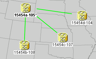
Each node has one E100T-12 card.
Problem
The spanning tree software on the ONS 15454 runs on the Timing, Communications and Control (TCC) card, which is a shared resource.
Note: This document uses 'TCC' to generically refer to all variations of the card.
This document addresses the limitation of a maximum of eight STP instances for a node.
Complete these steps in order to understand the problem:
-
Log into the Cisco Transport Controller (CTC) for 15454a-105.
Figure 2 – Expanded STP Instances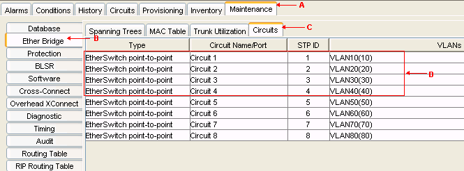
-
Click the Maintenance tab (see arrow A in Figure 2).
-
Click the Ether Bridge tab (see arrow B in Figure 2).
-
Click the Circuits tab (see arrow C in Figure 2).
The STP ID column displays eight different instances of STP. An attempt to create a circuit with a ninth STP instance fails with an error message (see Figure 3).
Figure 3 – VLAN/Spanning Tree Violation Error Message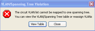


Solution
One way to avoid the error is to assign phantom VLANs that do not carry traffic. A phantom VLAN forces the spanning tree to collapse into the same instance. The solution is to collapse Circuit 1, Circuit 2, Circuit 3 and Circuit 4 into one STP instance.
Complete these steps:
-
Create a phantom VLAN. Complete these steps:
-
Log into CTC for 15454a-105.
-
Click the Circuits tab (see Arrow A in Figure 4).
-
Select Circuit 1 (see arrow B in Figure 4).
Figure 4 – Edit the Circuit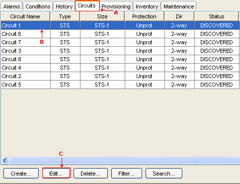
-
Click Edit (see arrow C in Figure 4). The Edit Circuit window appears (see Figure 5).
Observe the circuit map (see arrow A in Figure 5).
Note: In order to view the circuit map, you must check the Show Detailed Map check box (see arrow D in Figure 5).
Figure 5 – Edit Circuit: Circuit 1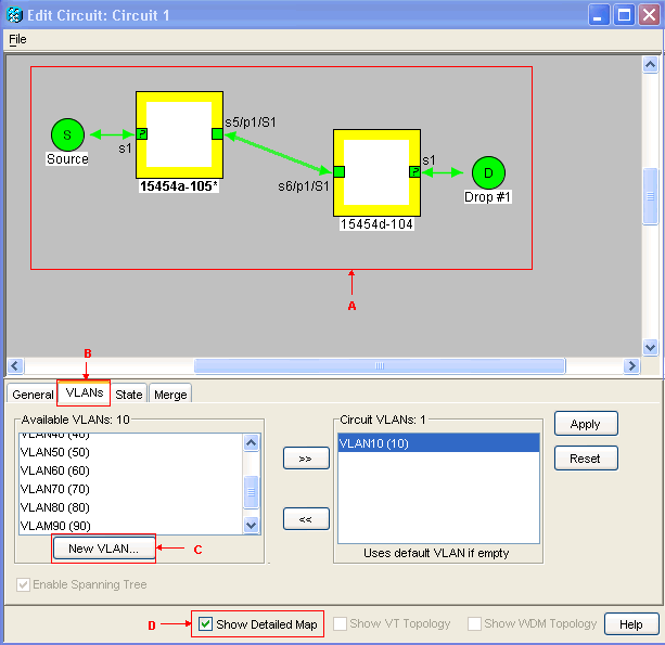
-
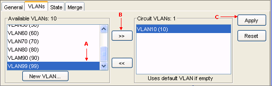
Click the VLANs tab (see arrow B in Figure 5).
-
Click New VLAN (see arrow C in ). The Define New VLAN dialog box appears.
Figure 6 – Define New VLAN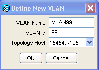
-
Enter the VLAN Name and VLAN Id in the appropriate fields. In this case, the VLAN Name is VLAN99 and VLAN Id is 99.
-
Click OK.
-
-
Add VLAN99 to Circuit 1. Complete these steps:
-
Add VLAN99 to Circuit 2.
-
Add VLAN99 to Circuit 3.
-
Add VLAN99 to Circuit 4.


Verification
Complete these steps in order to verify the result:
-
Click Maintenance > Ether Bridge > Circuits.
-
Compare arrow D in Figure 2 and arrow A in Figure 8. Observe that circuits 2, 3 and 4 collapse into STP ID 1 from STP ID 2, 3 and 4.
Figure 8 – Collapsed STP Instance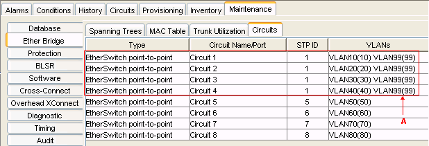

After the merge, the number of STP instances successfully reduces from 8 to 5. Now you can add another STP instance.
Related Information
 Feedback
Contact Cisco
- Open a Support Case

- (Requires a Cisco Service Contract)