Introduction
This document describes the supported network connectivity for various networks involved in Cisco DNA Center 3-node cluster deployment.
Prerequisites
Familiarize yourself with the basic information about the 3-node Cisco DNA Center cluster and High Availability (HA) with these articles:
Description
For Cisco DNA Center 1.2.8 version, the 3-node HA cluster is supported for Base Automation and SD-Access Automation. In 1.2.8/1.2.10, HA is still in Beta release for Assurance.
The HA of Cisco DNA Center offers more resiliency and reduces downtime when a node or service or a network link goes down. When a failure occurs, this framework helps to restore your network to its previous operational state. If this is not possible, Cisco DNA Center indicates that there is an issue that requires your attention.
Any time the HA framework of Cisco DNA Center determines that a change on a cluster node has taken place, it synchronizes this change with the other nodes. The supported synchronization types include:
-
Database changes, such as updates related to configuration, performance, and data supervision
-
File changes, such as report configurations, configuration templates, TFTP-root directory, administration settings, licensing files, and the key store
The current Cisco DNA Center software supports a minimum 3-node cluster for HA to work. Once the cluster is set up, it can manage single-node failure. A minimum of two nodes is required to set the quorum. Without a 2-node quorum, the cluster is declared down. If you use SD-Access Fabric then cluster failure only results in failure to provision Automation but still, your SD-Access fabric user network traffic continues to forward as Cisco DNA Center is not responsible for any Control or Data traffic.
In this document you look at various failure points and how the cluster mitigates the downtime in order to keep Cisco DNA Center operational at all times. You mainly focus on network connectivity aspects of a 3-node cluster. For services and all other information refer to the install and admin guide.
Network Connectivity
Cisco DNA Center uses these types of network connectivity:
1. 10 Gbps Cluster Link
2. 1 Gbps GUI/Management Link
3. 1 Gbps Cloud Link (Optional)
4. 10 Gbps Enterprise Link
5. 1 Gbps CIMC Link
It is assumed that proper intra-cluster-IP-ARP resolution happens and connectivity is ensured between all three nodes. In addition, it is recommended to have <10ms RTT between cluster links for all the scenarios.
Failure Scenarios and Cluster Behavior
In general, cluster services redistribution happens under these conditions:
1. Single node goes down: Services are distributed to the other two nodes and the cluster is still operational.
2. Enterprise network link goes down for single node: No service redistribution. Only reachability to the enterprise network from the failed node does not work.
3. Cluster Network link goes down: Services are redistributed to the other two nodes and the cluster is still operational.
4. All other network links go down except the cluster link for a single node: A node is not able to service the expected functions but all services and clusters operate normally.
5. Service failure on a single node: The service tries to restart. In most of the scenarios, it tries to restart on the same node but currently, there is no affinity to the node so it can start on any node.
6. Network switch goes down: Based upon different types of topology, the cluster operates normally or the service is redistributed or everything is down.
Physical Topology Option 1
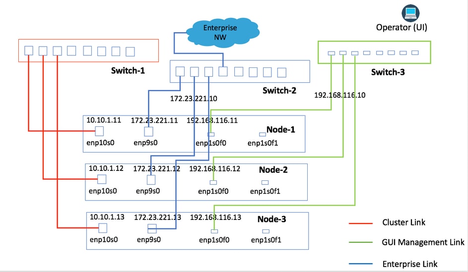
Initially, connectivity to the network was recommended by the engineering. Both Image 1 and Image 2 provide connectivity where each type of Network link from all nodes is connected to the same physical switch. For example, the Enterprise network link from all three nodes is connected to the same physical switch.
Image 1
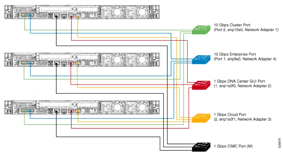
Image 2
This topology provides these types of failure scenarios where the cluster is still operational:
1. Single Node Failure
2. Enterprise Network Link Failure
3. Cluster Link Failure
4. Service Failure
This topology is not able to manage a complete switch down for any of the network links.
|
Failure Condition
|
Impact/Cluster State
|
|
Single Node Down
|
The cluster is still operational with the other two nodes.
|
|
Single Link Down for any of the Network Link
|
The cluster continues to operate normally. Services are distributed only if the cluster link goes down.
|
|
Switch goes Down
|
The cluster is unusable for automation.
|
Physical Topology Option 2 (Most Recommended)
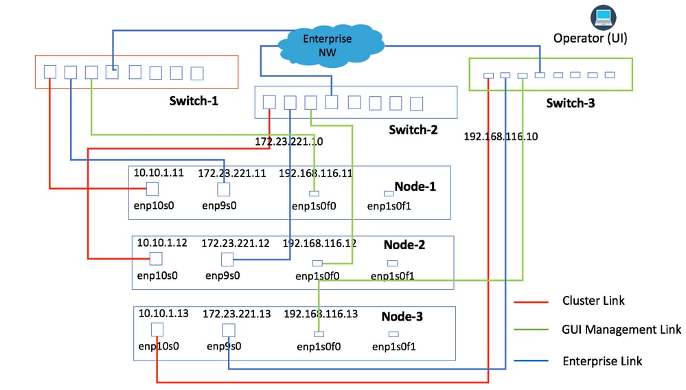
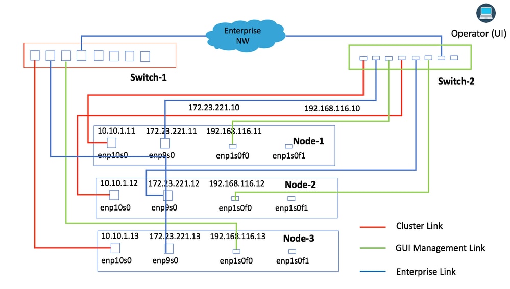
Image 3 provides the connectivity where all of the Network Links from the same node are connected to the same physical switch. All links from a node are connected to the same physical switch with separation with the use of VLANs, or they can be connected to different switches. For example, Link from Node-1 is connected to Switch-1, Link from Node-2 is connected to Switch-2, and so forth.
Image 3
This topology provides these types of failure scenarios where the cluster is still operational:
1. Single Node Failure
2. Enterprise Network Link Failure for Single Node
3. Cluster Link Failure for Single Node
4. Service Failure for Single Node
5. Single Network Switch Failure for Single Node
|
Failure Condition
|
Impact/Cluster State
|
|
Single Node Down
|
The cluster is still operational with the other two nodes.
|
|
Single Link Down for any of the Network Link
|
The cluster continues to operate normally. Services are distributed only if the cluster link goes down.
|
|
Single switch goes down
|
The cluster is still operational with the other two nodes.
|
Physical Topology Option 3 (For Data Center Type Environment)
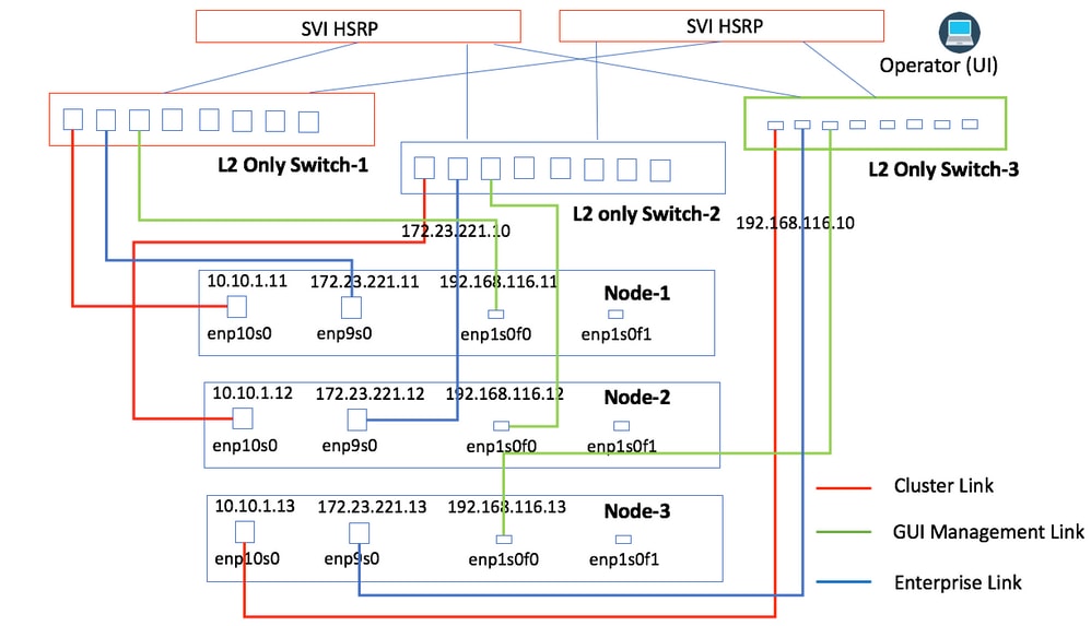
This topology is similar to Option 2, except, you can have three Layer-2 switches that connect to the gateway. All information is similar to Option 2.
Image 4
Physical Topology Option 4 (Not Recommended)
Image 4 provides the connectivity where two nodes are connected to the same switch while the other node is connected to a different switch. This topology is least recommended as failure to switch which has multiple links connected can bring down the cluster.
This topology provides these types of failure scenarios where the cluster is still operational.
1. Single Node Failure
2. Enterprise Network Link Failure for Single Node
3. Cluster Link Failure for Single Node
4. Service Failure for Single Node
This topology is not able to manage a complete switch down for any of the network links.
|
Failure Condition
|
Impact / Cluster State
|
|
Single Node Down
|
The cluster is still operational with the other two nodes.
|
|
Single Link Down for any of the network links except the Cluster Link
|
The cluster continues to operate normally.
|
|
Single Cluster Link Down
|
Services are distributed to the other two nodes and continue operation.
|
|
Single switch goes down
|
The cluster can go down if a switch that has multiple links goes down.
|
Some additional failure scenarios and states are covered in Administrator Guide for Cisco DNA Center 1.2.10.
 Feedback