Architecting for End-to-End Low Latency in Wireless Networks White Paper
Available Languages
Bias-Free Language
The documentation set for this product strives to use bias-free language. For the purposes of this documentation set, bias-free is defined as language that does not imply discrimination based on age, disability, gender, racial identity, ethnic identity, sexual orientation, socioeconomic status, and intersectionality. Exceptions may be present in the documentation due to language that is hardcoded in the user interfaces of the product software, language used based on RFP documentation, or language that is used by a referenced third-party product. Learn more about how Cisco is using Inclusive Language.
Achieving low latency in wireless networking requires a focus on end-to-end IP traffic ― from the device all the way to the application, wherever it is located (e.g., in a data center or cloud provider), and back. This white paper explores how low latency could be achieved in different wireless applications in private 5G, Wi-Fi, and Cisco Ultra-Reliable Wireless Backhaul (URWB) deployments.
Everybody wants low latency in networks, but what does low latency really mean?
In Voice over IP (VoIP), 150 milliseconds (ms) of latency in one direction is not noticeable by users, and therefore is perfectly acceptable. With applications like collaboration (Webex, Microsoft Teams), Office 365, messaging, and 3D collaboration with augmented and Virtual Reality (AR/VR), sub-50-ms bidirectional response times are desired. Similarly, if you’re using wireless connections to run an Autonomous Mobile Robot (AMR) or an Automated Guided Vehicle (AGV) in a factory, sub-20-ms response times in a high-throughput network are required, while some process control loop traffic requires 10 ms or less.
In network design, achieving end-to-end IP latency to meet the needs of specific applications requires an understanding of the data flow, technologies, and topology of the overall network architecture. However, quite often specific Layer 1 and Layer 2 technology developers advertise only their own latency values while neglecting to factor in end-to-end IP latency, which is the sum of all Layer 1 and Layer 2 infrastructures that IP flows traverse.
End-to-end IP latency is usually calculated in one direction: from the wireless device to the wireless network, IP transport network, and application server (Figure 1). RTT is the calculation of bidirectional latency (e.g., the time required for a network ping). In addition, the processing time required before a response is sent back must also be considered in calculating overall latency.
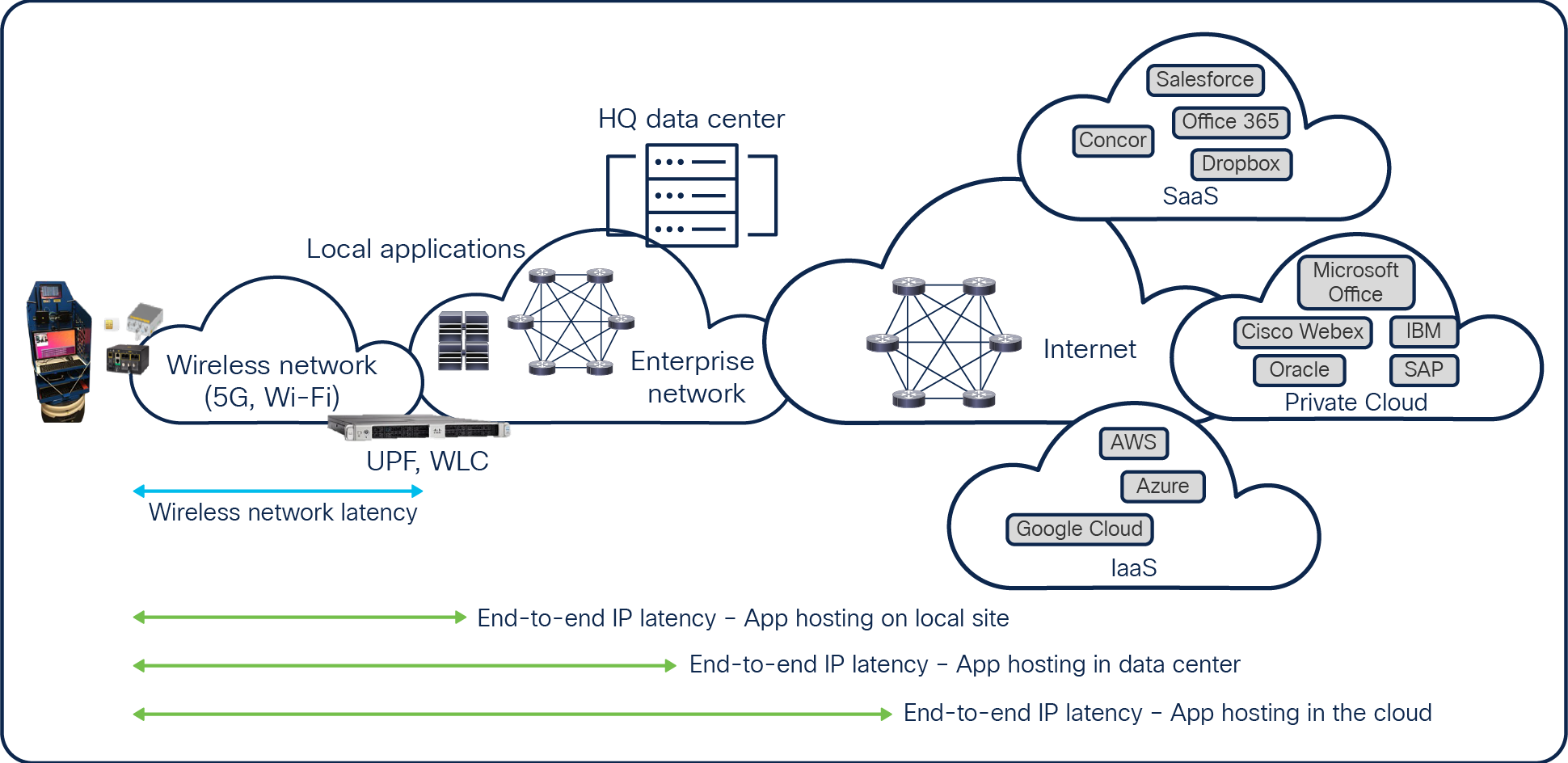
End-to-end IP latency
Latency, as defined in the 3rd Generation Partnership Project (3GPP) TR 38.913, describes the user plane latency at the radio interface. The focus is from the time a transmitter’s Packet Data Convergence Protocol (PDCP) receives an IP packet to when the receiver’s PDCP receives it and delivers it to the user plane upper layers (for example, to the relay in the base station). But the radio interface and user plane computation are only one segment of what contributes to total IP flow latency.
3GPP efforts related to 5G latency have focused on reducing and controlling the time spent by traffic over the radio network. While latency target numbers were defined dependent on the wireless service type (such as eMBB ~4 ms or URLLC ~1 ms) for a specific data flow throughput, delays and throughput loss from various network functions must be factored in when designing networks, as actual latency will be higher in typical operations.
Like 3GPP, the IEEE 802.11 working group looks at improving the deterministic aspects of the Wi-Fi protocol. A recent study of deterministic Wi-Fi evaluated the latency of existing Wi-Fi versions and how enhancements could be made available on the ongoing IEEE 802.11be or Wi-Fi 7 specifications (Figure 2). This evolution of enhancements, which also demonstrates the need for collaboration between vendors, is designed to meet new requirements by industrial applications (for example, for AMR and AR/VR applications) with the correct network design of the Wi-Fi segment.
Each wireless technology standard tries to improve the radio characteristics of the solution, but each represents only one of many enhancements to be considered in a network design.
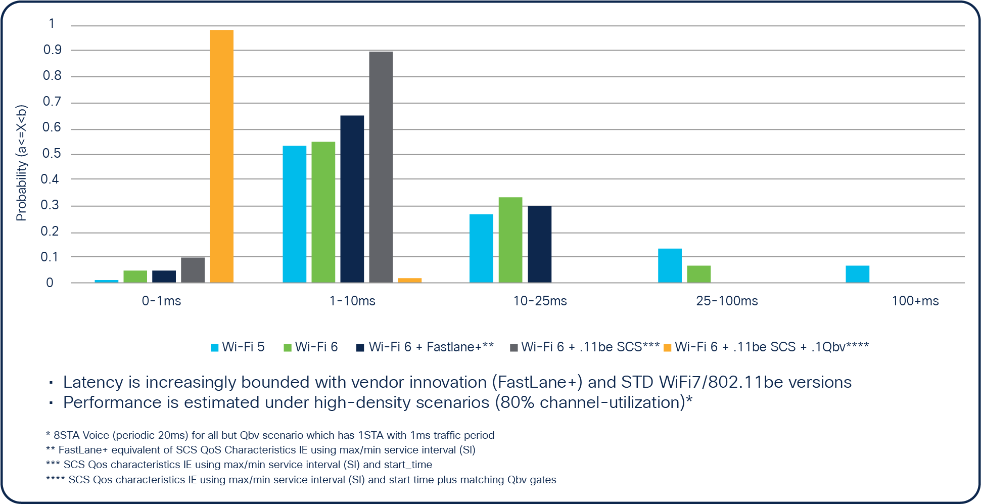
Evolution of Wi-Fi latency
Cloud and data center proximity and latency
In calculating end-to-end IP latency, it’s important to consider the typical Round-Trip Time (RTT) latency between an end user and a cloud provider or Content Distribution Network (CDN) service provider, as shown in Figure 1. In a network design aiming for 150 ms of RTT latency, the time split between each network segment or building block from the local device to its application must be estimated. A device attaches to a local wireless network with its over-the-air latency, then data is transited over public and private IP infrastructure, including switches, routers, and firewalls in the round-trip path. This often means that the data incurs unpredictable internet latency before reaching the application.
Achieving lower RTT latency is simplified with the closer proximity of applications hosting the wireless devices. In the calculator in Figure 3, RTT through fiber links is estimated, which helps us understand the additional delay added through typical fiber optic paths when communicating with cloud or data center applications. If a network design targets less than 10 ms of RTT latency through the IP transport infrastructure, the selection of a managed cloud provider is required, one that offers data center services located within 200 kilometers of the device’s location. The example in Figure 3 is based on France, which mandates at least 10 regional data centers for such coverage, without considering data and application movement around the cloud.
This example perfectly illustrates why achieving lower end-to-end IP latency (such as 5 ms) for edge computing is a mandatory component of application hosting that must be collocated within campuses or regional data centers.
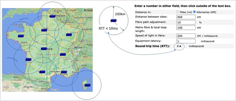
5G Cloud topology with a sub-10-ms RTT (Source: OHVCloud)
Here is what low-latency architectures look like in private 5G, Wi-Fi 6/6E, and Cisco URWB deployments.
Achieving low latency with private 5G
In different types of 5G service, 3GPP specifications differentiate the implementation for each service type when discussing latency capabilities, including the typical data flow characteristics used to define the latency target values. 5G Enhanced Mobile Broadband (eMBB) supports bandwidth-driven use cases such as high-definition video (4K/8K) that require high data rates (> 1 Gbps) for a given coverage area and number of users and devices. 5G Ultra-Reliable Low Latency Communications (URLLC) is meant to address real-time communications for industrial use cases that require sub-5-ms end-to-end latency and an uptime of 99.9999%.
These advanced 5G solutions include optimizations at every step of the radio hardware and uplink and downlink transmission processes. New radio features address low-latency communications, allowing for a variable Transmission Time Interval (TTI) that can scale from 1 ms down to ~140 microseconds, depending on whether spectral efficiency in eMBB or low latency in URLLC is the main goal.
In a private 5G topology within a factory, as shown in Figure 4, an industrial robot connected to the Radio Access Network (RAN) is shown at lower left. Once IP packets exit the robot, they are encapsulated inside a tunnel and the intermediate devices don’t see IP packets but instead recognize the MAC layer encapsulation.
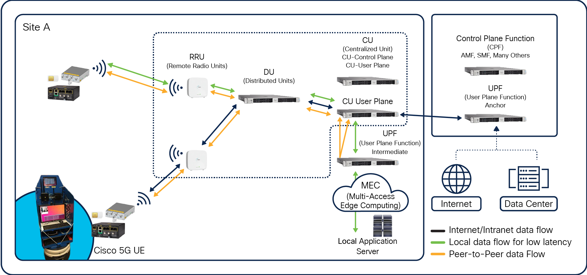
5G data flow with an open RAN architecture
The IP packets exit the tunnel at the User Plane Function (UPF). The UPF is the interconnect point between the mobile infrastructure and the data network (that is, encapsulation and decapsulation of General Packet Radio Service [GPRS] Tunneling Protocol for the user plane). The packets are then routed to the application, either locally or to a data center or an internet cloud service. One benefit is that the UPF can be distributed, allowing a central UPF to serve as anchor for the overall network, while the local UPF may be deployed on a site to reduce the path to local applications.
Again, the location of cloud providers or company data centers has a major impact on latency. The closer they are located to the end devices, the lower the latency. Latency results from a full path through all these devices.
In addition to the distributed UPF, a Multiaccess Edge Computing (MEC) function is defined to better handle local application services. Tunnels are terminated at local smaller data centers nearer the cell radio. This approach can eliminate network delays from end-to-end latency because the traffic isn’t traversing back to a central data center or the internet, therefore achieving sub-10 ms for critical applications.
Achieving low latency with Wi-Fi
IEEE 802.11 standards are continuously and rapidly evolving, with the latest version ― covering Wi-Fi 6 and 6E ― increasing network capacity and bandwidth and reducing latency (Figure 2). Even though Wi-Fi operates in unlicensed bands, it is strictly regulated by countries. Local regulations define maximum power levels of access points to avoid interference between users. This in turn determines range, coverage, penetration, and signal strength. As previously discussed, the next generation of the Wi-Fi protocol is expected to enhance its determinism, allowing better latency control in a network design.
Wi-Fi low-latency architecture
Wi-Fi and 5G use different types of encapsulations, but IP packets in a W-Fi network similarly move from access points to the wireless radio network and through tunnels to a Wireless LAN Controller (WLC). In a network design, the end-to-end IP path to applications in a cloud or data center from the WLC is identical to that in the 5G use case, since it is independent from the selected wireless technology. Similarly, for private 5G deployments, if low latency is required for an application, a Wi-Fi WLC for the application server path should be designed to yield a path that is as short as possible.
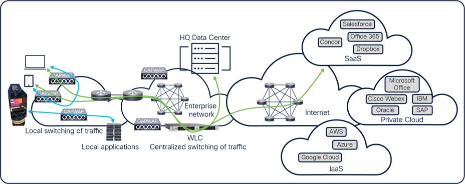
One main benefit of Wi-Fi architectures is the ability to do local switching without reaching a WLC (Figure 5), another factor that may contribute to lower latency in a design.
Achieving low latency with Cisco Ultra-Reliable Wireless Backhaul
Cisco Ultra-Reliable Wireless Backhaul (Cisco URWB) is a wireless WAN backhaul technology derived from Wi-Fi and designed to serve mobile network environments such as trains, buses, subways, remotely controlled cranes, AGVs, and AMRs. It can also be deployed as a fixed infrastructure, providing backhaul where fiber can’t go or is too expensive. Cisco URWB is especially well suited for connectivity between mobile networks (such as vehicles) and a fixed infrastructure, optimized to quickly move the mobile device’s communications within a fixed wireless infrastructure before breaking. Cisco URWB networks can be designed for Layer 2 use cases (such as AGVs or AMRs in a distribution center) as well as Layer 3 use cases (such as subways), allowing network mobility through multiple locations a few miles apart.
Cisco URWB technology provides low-latency, highly reliable, long-range, high-bandwidth connections that can handle endpoints moving at high speeds with zero-delay handoffs. Operating in unlicensed frequencies, the Cisco URWB segment requires an appropriate design to control latency and fast handover in less than 5 ms, while the end-to-end IP infrastructure beginning at the Cisco URWB gateway is like Wi-Fi and 5G topologies.
Recent enhancements were made to Cisco URWB to deliver uninterrupted connectivity to fast-moving devices by sending high-priority packets via redundant paths. Cisco patented Multipath Operations (MPO) technology can duplicate protected traffic up to 8x and avoid common paths, and it works alongside hardware availability for lower latency and higher availability, limiting interference and hardware failures.
A Cisco URWB topology is shown in Figure 6. The onboard layer at the bottom represents a vehicle that contains a radio connected to a base station. Data from the vehicle is encapsulated on a centralized controller and then decapsulated as IP packets on the IP network. Again, lower levels of latency can be realized per application by moving the data center or cloud provider closer to the end device.
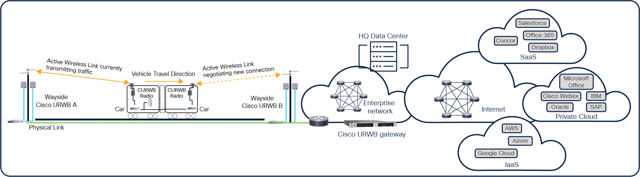
Cisco Ultra Reliable Wireless Backhaul topology
Adoption of a particular type of wireless network depends upon each company’s strategy and operational use cases. However, none of the wireless technologies can achieve low latency without the proper network design. Radio latency must be estimated in the context of end-to-end IP latency and round-trip delay, while each application’s requirements must dictate the network design. Many different factors contribute to reducing latency. But one that is shared by 5G, Wi-Fi, and Cisco URWB is the proximity of applications, either local, in data centers, or in clouds where data is being processed.
Whether on a factory floor, in a university research center, on a high-speed train, or in a branch office, the better the network design, the lower the probable service latency.