Meeting the Network Requirements of Non-Volatile Memory Express (NVMe) Storage with Cisco Nexus 9000 and Cisco ACI White Paper
Available Languages
Bias-Free Language
The documentation set for this product strives to use bias-free language. For the purposes of this documentation set, bias-free is defined as language that does not imply discrimination based on age, disability, gender, racial identity, ethnic identity, sexual orientation, socioeconomic status, and intersectionality. Exceptions may be present in the documentation due to language that is hardcoded in the user interfaces of the product software, language used based on RFP documentation, or language that is used by a referenced third-party product. Learn more about how Cisco is using Inclusive Language.
Dr. Joel Snyder is an internationally known expert in telecommunications networks, messaging, and security. He is currently a Senior Partner at consulting firm Opus One. With over twenty-five years of experience, Dr. Snyder has helped organizations worldwide with their messaging, networking, and security projects.
For network managers, the evolution of network-attached storage has not been an issue: the network was so fast and the spinning hard drives so slow that natural network upgrades to 10G Ethernet and faster Fibre Channel speeds have been sufficient to meet the networking needs of storage systems. With the introduction of Non-Volatile Memory Express (NVMe) ultra-fast solid-state storage, that simple view is no longer true: storage teams now have the ability to saturate networks with incredibly fast devices. Network managers need to look closely at this new generation of storage to understand what’s different – and how they can meet the performance demands of truly high speed storage.
Network-based SANs using NVMe technology – known as NVMe over Fabric (NVMe-oF) – present significant challenges for the network manager, including:
● Flexibility – Integrate NVMe systems into existing networks using evolving protocols
● Security – Securely deliver networking to NVMe storage systems, ensuring that clients and servers are isolated and that network connections between devices are tightly controlled
● Performance – Deliver a high-performance network that meets the strict latency and loss requirements of these new storage protocols, even in the face of congestion and oversubscription
● Visibility – Look deep across a whole network fabric to ensure that SLAs are being respected from end to end, all the way from client to server, and that capacity is available to handle failover events
● Manageability – Accurately and easily deploy complex configurations, including access controls and traffic engineering across large switch fabrics
This white paper dives deep into each of these five areas and shows how network managers can meet the challenges presented by NVMe-oF in modern data centers using the features built into the Cisco Nexus® 9000 family of switches and management tools.
| Challenge |
Solution |
| Flexibility |
Modern VxLAN technology provides a simple tool for network managers to build fully isolated and performance-controlled “subnetworks,” handling multiple protocols without requiring physically separate networks. Taking advantage of integrated networking lets network managers build on their investment in high-availability, high-speed technology. |
| Security |
Switch fabrics that allow for multitenant configuration, separate VRF instances, and sophisticated access control lists deliver the security characteristics that storage managers are accustomed to in traditional Fibre Channel networks. |
| Performance |
Careful topology design using newer spine-and-leaf architectures and high-speed 100Gb and 400Gb links set up the network infrastructure, allowing intelligent buffering, priority flow control, and QoS features to meet strict latency and loss characteristics of NVMe-oF storage systems. |
| Visibility |
Flow-based network monitoring is not precise enough for storage networking. Network managers need to be able to see deeply into end-to-end performance with monitoring tools that reach into the switch hardware to report on critical metrics. |
| Manageability |
Automated, easy-to-use GUI-based management tools that can push a full and consistent configuration to an entire switch fabric are a must for storage networking. |
Introduction to NVMe and NVMe-oF
For network managers, the evolution of network-attached storage has largely been a non-issue: the network was so fast and the spinning hard drives so slow that natural network upgrades to 10G Ethernet and faster Fibre Channel speeds have been sufficient to meet the networking needs of storage systems. That simple view is no longer true: storage teams now have the ability to saturate networks with incredibly fast devices. Network managers need to look closely at this new generation of storage to understand what is different – and how they can meet the performance demands of truly high-speed storage.
A quick introduction to Non-Volatile Memory Express (NVMe) and NVMe-over-Fabrics (NVMe-oF) will help to put all of this into perspective and show where high-speed storage is going over the next decade.
Until recently, storage systems have been based on Hard Disk Drives (HDDs), spinning media: magnetic platters and moving heads that have been the logical progression of a technology more than 60 years old. As drive technology advanced with faster and smaller devices, the storage industry coalesced around a model of a drive controller connected to HDDs using a parallel or serial bus, such as SAS (Serial Attached SCSI) or SATA (Serial ATA).
This well-known and interoperable technology chain from disk drive to bus to controller to computer is well-balanced for performance – so long as the disk drives act like traditional HDDs. The introduction of Solid-State Drives (SSDs), however, created a strong imbalance in the world of storage. Suddenly, “disk drives” could offer RAM-like performance with near-zero latency (that is, seek time) and transfer rates in excess of 20 Gbps. The first real commercial deployments of these SSD drives were as drop-in replacements for HDDs in traditional storage systems. SSDs provided higher speed, lower latency, less heat and power consumption, and no need to reengineer existing well-known and widely-deployed hardware. They were a win-win for the storage industry.
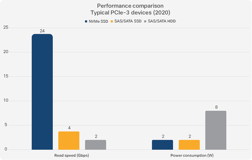
NVMe solid-state disks are dramatically faster than both spinning and FLASH-based SAS/SATA drives, yet have the same power consumption as FLASH-based drives. PCIe-4 devices arriving in the marketplace this year will be even faster.
However, simply putting SSDs into existing storage systems has a drawback: it doesn’t take full advantage of the potential performance increase of the underlying technology. To really benefit from the potential of SSD devices requires a rethinking of the way that storage systems connect to servers.
Storage vendors tried several approaches in designing specifically for SSD-based storage, and the ones that caught the most traction in the industry were based on connecting storage devices directly to the PCI Express bus. After multiple proprietary devices were built, the storage and server industry came together in 2011 to create NVMe: Non-Volatile Memory Express.
NVMe is a protocol more than anything else, not a connector or a form factor or an interface specification. NVMe differs from other storage protocols like SATA because it treats the SSD devices much more like memory than hard drives. The NVMe protocol is designed from the start to be used over the PCIe interface, and thus connect almost directly to the CPU and memory subsystems of the server.
In multicore environments, NVMe is even more efficient, because it allows each core to independently talk to the storage system. With more queues and deeper queue depth in NVMe, multiple CPU cores can keep the SSDs busy, eliminating even internal bottlenecks to performance. NVMe is a NUMA-aware protocol, taking advantage of the advances in memory subsystem design in newer CPUs. Overall, storage with SSDs and the NVMe protocol can deliver dramatically higher I/O Per Second (IOPS) and lower latency than the same SSDs using SATA or SAS.
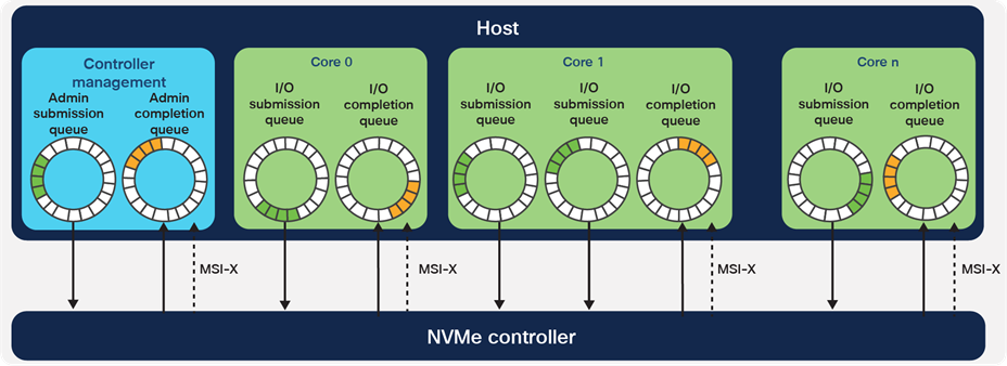
Because NVMe controllers connect directly to the host using the PCIe bus, each CPU core can have multiple I/O queues, increasing parallelism and reducing storage system latency. (Figure courtesy NVM Express)
For network managers, all of this emphasis on improving storage performance within a single server may be interesting to learn, but it doesn’t really affect things from a network point of view. This technology allows individual servers to operate at higher speeds, but there’s no fundamental change for network teams here.
However, remember that NVMe is a protocol specification[1]. And this is where it gets interesting for network managers, because a protocol that can be run inside a server can also be run between servers, over a network. In the world of NVM Express, this is the next big thing, which they call “NVMe over Fabrics” (NVMe-oF).
NVMe-oF is a series of specifications, all from industry group NVM Express, that define how to extend the NVMe protocol using network fabrics such as Ethernet and Fibre Channel. NVMe-oF can deliver higher performance storage than existing protocols. If the advocates for NVMe have their say, storage systems built on NVMe and NVMe-oF will be the go-to answer for data centers, pushing out older technologies such as SCSI-style Fibre Channel Protocol and iSCSI.
In designing NVMe (and NVMe-oF), the engineers were driven by one goal: gain the highest performance possible, without compromises. And, honestly, NVMe-oF is a complicated protocol that demands a lot from a network. It’s not just a matter of saying “oh, this is another TCP or UDP application on my network.” NVMe-oF imposes very strict requirements on the performance of the network, including throughput, latency, and error rate – concepts that add layers of complexity to the “best effort” engineering that underlies most data center Ethernet networks.
These layers of complexity require a higher level of engineering and performance management, and network managers will need to work harder to make sure that their data center networks are capable of handling NVMe-oF. One goal of this white paper is to explain the various special requirements of NVMe-oF to network managers, so that it’s clear how to build data center networks that work when NVMe-oF storage systems begin to be wheeled in the door.
If NVMe were a typical storage protocol, running it over data center LANs would not be difficult. However, NVMe looks much more like a memory protocol: it has the semantics of memory, it came from the world of the PCI Express bus, which transfers data directly into CPU memory, and it assumes a super-low latency, multi-threaded, zero-loss environment.
When translating NVMe into a network-based protocol, the NVMe-oF designers elected to retain the same basic memory model of NVMe: a series of many (up to 65,535) paired queues (submission/completion) and attached pointers to memory buffers. This creates network protocol complexity, because the traditional network “stream of bytes” doesn't match NVMe very well.
Network managers need to know about three transport bindings to run NVMe-oF in their data centers: NVMe over Remote Direct Memory Access (NVMe/RDMA), NVMe over TCP (NVMe/TCP), and NVMe over Fibre Channel (NVMe/FC).
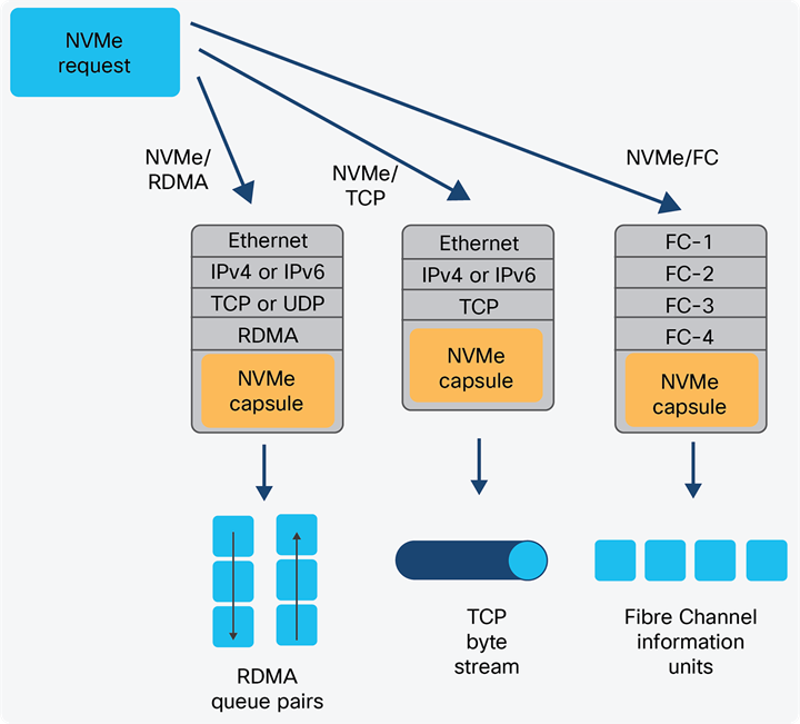
NVMe-oF bindings provide the mechanism to transport the NVMe memory-based capsules between systems. Standards-based network protocols are the base for each binding, insuring interoperability with existing network devices.
When the NVM Express team went looking for a way to encapsulate NVMe over networks, they found one network fabric ready-made for the problem: RDMA (Remote Direct Memory Access), standardized through a joint effort of the RDMA Consortium and the IETF back in 2007. RDMA is a series of protocols that use specialized Network Interface Cards (NICs) in servers to accomplish extremely high-performance, memory-to-memory data transfers. In RDMA, almost everything is off-loaded from the CPU and pushed to the “rNIC” (RDMA NIC). The goals of RDMA are to reduce the context switches between user and kernel space, allow direct memory copies to and from the host CPU, and offload protocol processing to the NIC from the CPU. Because RDMA bypasses the operating system kernel, network stack, and drivers, it’s dramatically faster than traditional OS-based TCP/IP network communications. The result is ultra-high memory-to-memory transfer rates, over standard Ethernet networks – perfectly matched to a protocol like NVMe.
When it’s actually running in data centers, RDMA goes by other names – and creates other complications for network managers. The first popular RDMA implementation in data centers was InfiniBand, a network interconnect used in supercomputers, which requires a different physical layer network. Network managers of scientific data centers with supercomputers may have InfiniBand hardware running today in parallel with their Ethernet networks.
RDMA over Converged Ethernet (RoCE) brings the benefits of RDMA to Ethernet. RoCEv1 was a nonroutable protocol running directly on top of Ethernet. RoCEv2 encapsulates RDMA inside of UDP, but requires “Converged Ethernet”: a tight configuration of Layer 2 and Layer 3 devices aimed at eliminating packet drops from oversubscription, prioritizing RoCE traffic over other IP traffic, and end-to-end congestion management.[2] These configuration tools are present in most modern switches and routers, but many network managers – accustomed to the high performance over “best effort” infrastructure they see in most TCP and UDP protocols – may not have bothered to configure them.[3]
iWARP (not an acronym) is another variation of RDMA, standardized in conjunction with the IETF, that runs over either standard TCP or the slightly-more-esoteric SCTP. Some network managers may not even realize that they have iWARP running inside their data centers, because once the rNIC is installed, the underlying RDMA protocols are no different from other IP traffic.
NVMe over RDMA (NVMe/RDMA) is the most complex of the fabrics used to provide remote access to NVMe, but because of the higher performance, it is also preferred by storage managers. Network managers who find themselves with a request to provide data center support for NVMe/ROCE should carefully review the configuration and performance limits required.
Because Fibre Channel is so popular with storage managers, it was natural for the NVMe-oF designers to also define a way to run NVMe over a Fibre Channel network. In NVMe over Fibre Channel (NVMe/FC), the existing Fibre Channel lower layers are used to transfer NVMe submission and completion queue entries (capsules). The “FC-4” layer is used to map protocols such as SCSI to Fibre Channel semantics; in the case of NVMe, Fibre Channel Protocol (FC-4) Command, Response, and Data Information Units (IUs) carry NVMe queue entries and associated data.
Network managers who have parallel Fibre Channel networks and switching infrastructure in their data centers can continue to use these devoted resources as the transport for NVMe-oF. However, typical Fibre Channel deployed speeds of 4—16—32 Gbps may be insufficient to really take advantage of the performance increase available in NVMe devices. While storage managers may be happy with the performance of Fibre Channel at 16—32 Gbps, new applications coming online, such as in-memory databases, can bottleneck traditional disk systems very quickly and are drivers for faster NVMe storage and high-speed NVMe-oF networks.
While the ability to segregate and separate storage networking from data networking has helped reduce management conflict and finger pointing in data centers, the inefficiency of buying and running parallel networks – especially in large hyper-scale data centers where NVMe will be a natural storage system – makes this a good time to push for a unified network architecture based on the less-expensive high-performance 100 Gbps NICs and 400 Gbps inter-switch links now commonly available.
NVMe over TCP (NVMe/TCP) is the simplest version of NVMe-oF for network managers to understand. Each NVMe queue pair turns into a TCP connection between the host and storage controller, and the NVMe capsules are simply packed into TCP byte streams.
At this point, most network managers are probably thinking “well, let’s just use that, then.” If it were only that simple. NVMe has a very strict end-to-end latency requirement of 10 μsec, and unless the network infrastructure is designed specifically to deliver low latency, then NVMe may not operate properly. In addition, the offload capabilities of protocols such as RDMA (with RoCE or iWARP) using special NICs, can give a significant performance boost by reducing protocol processing overhead and expensive memory copies.
In the remainder of this white paper, we’ll discuss the specific issues of NVMe-oF that network managers should be aware of. We’ll compare the performance and behavior of NVMe/TCP with NVMe/RDMA (RoCE), so that network managers are well informed when they sit down with storage managers to discussion how to bring NVMe technology into modern data centers.
Overview of the Network challenges of NVMe-oF
Network managers beginning to integrate NVMe storage systems need to consider five specific challenges that this next-generation storage will present for data center networks.
| Area |
Networking challenge for NVMe-oF |
Why? |
| Flexibility |
Network managers have to be prepared to deal with protocol and media changes, often with little notice. |
NVMe-oF protocols are an evolving area, so storage managers may need to adjust their configuration to take advantage of higher-performance technology or changes in server hardware. |
| Security |
Network managers may need to configure logically separate networks for storage networking if storage managers demand them as part of their storage security strategy. |
The isolation built into having a physically separate Fibre Channel network made storage managers more confident of the security of their deployment. When storage and data networking are mixed in the same infrastructure, this can be a concern for storage managers used to FC technology. |
| Performance |
Network managers must carefully control latency, loss rate, and oversubscription end-to-end between storage servers and clients; NVMe-oF performance requirements can be very strict. |
NVMe-oF specifications call for less than 10 μsec of end-to-end latency, a challenge for many traditionally-configured data center networks. NVMe-oF operations, especially in RDMA environments, are not tolerant of packet loss. |
| Correctness |
Configuration generators and other automation tools will help network managers ensure that NVMe-oF network policies are applied consistently and completely. |
The NVMe-oF networking requirements described above call for a very high level of control of complex network policy configurations for end-points. When automation tools are not available, these policies can quickly overwhelm network managers accustomed to traditional command-line configuration environments. |
| Monitoring |
Troubleshooting, performance monitoring, and ensuring SLA compliance of high-volume NVMe-oF protocols requires a different toolset than traditional NetFlow-style analyzers. |
NVMe-oF flows are long-lived and between a small set of endpoints, which is a poor fit for traditional flow-based monitoring tools. The need to tightly control for packet loss and latency distribution calls for a different set of metrics than many network engineers are accustomed to using. |
In the following five chapters, we will go into greater depth in each of these specific challenges. We’ll discuss more completely the issues that network managers will face, and we’ll provide some specific recommendations on how to conquer these challenges using Cisco ACI® software and Cloudscale ASIC—based hardware.
Networking challenge: flexibility
NVMe-oF starts on Day 1 with a networking challenge: lots of choices in protocols. As a new family of standards, NVMe-oF doesn’t dictate a particular networking technology, and there is no best-practice choice of the “right way” to deploy NVMe storage systems in large data centers. With UDP-based NVMe/RDMA, TCP-based NVMe/TCP, and even NVMe over Fibre Channel, storage managers may come to the table not knowing exactly how they want to integrate this new technology or what protocols and traffic engineering the network will need to support. In addition, existing storage systems may include a mix of protocols such as NFS, SMB, and iSCSI, further complicating the networking.
Network managers can support their storage counterparts by offering maximum flexibility in protocol and networking technology. To support this flexibility, network managers should integrate storage networking and data networking using the same infrastructure. This will allow the quick reconfiguration of network paths and connections to support the needs of storage manager who may want to jump between different protocols and connectivity as they install and deploy NVMe storage systems.
Integrated infrastructure simplifies management, troubleshooting, monitoring, and capacity planning. But although storage clients and servers should use the same LAN and WAN infrastructure as the rest of the data center, some separation is called for. In other words, NVMe should share infrastructure, to accommodate maximum flexibility, but should be isolated within that infrastructure, to meet the performance and security requirements of storage networks.
NVMe storage devices should be isolated wherever possible to provide predictable high performance, increase security, and minimize the networking burden on storage clients and servers. In today’s converged network data centers, multitenant designs and isolated Virtual Routing/Forwarding (VRF) instances are the basic building blocks. On top of this base, Virtual Extended LAN (VxLAN) technologies establish connectivity between devices in a secure and highly controlled manner.
Network managers use VxLANs to build extended Layer 2 networks that join storage servers and clients in the most transparent way possible. The benefits of using VxLAN technology include:
● Isolation at the Ethernet layer, making devices VLAN-independent. By using VxLAN technology, network managers don’t have to manage limited VLAN space within and between data centers – everything is transparent.
● Isolation at the IP layer, making devices IP-independent. VxLANs provide Layer 3 isolation, meaning that storage systems can be moved freely without worrying about IP addressing and subnetting issues.
● Performance management using traffic engineering, especially required for NVMe/RDMA protocols. VxLANs with advanced technology such as Cisco ACI can also attach traffic engineering and Quality of Service (QoS) configuration to a VxLAN, automatically provisioning the network as needed to meet storage networking needs.
● Better performance compared to the traditional Spanning Tree Protocol (STP), both in failover (faster convergence) and speed (ECMP across all fabric uplinks)
VxLAN is an ideal technology for multiprotocol storage in data center environments: VxLANs scale far beyond traditional VLANs, offer the same traffic and protocol isolation that VLANs do, aren’t limited by the old Spanning Tree Protocol “routing” algorithm, and easily allow extending a single Layer 2 network within and between data centers by encapsulating Layer 2 traffic inside UDP/IP layer 4 tunnels. VxLANs are also great tools for building microsegmentation within a data center, supporting the shift to more secure multitenant and application-centric networks.
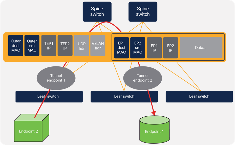
VxLAN encapsulates traffic between two endpoints, building internal tunnels to create virtual LANs even across data centers.
Managing VxLAN tunnels, though, can be a challenging task if done manually. A single spine-and-leaf topology is difficult enough, but data center environments that span multiple rooms, floors, or buildings also mix in an IP underlay to transport the VxLAN traffic. One of the benefits of switches that use Cisco® Application Centric Infrastructure (ACI) technology is that VxLAN mechanics are handled automatically and transparently behind the scenes, reducing the load on the network manager and helping to avoid configuration errors. ACI-based switches such as the Cisco Nexus 9000 family can self-configure VxLAN traffic across the switching and routing fabric, automatically fine-tuning and optimizing the routing.
Any discussion of multiprotocol support for storage needs also to consider Fibre Channel. Network managers don’t really appreciate how much storage managers love their Fibre Channel networks. Isolated, secured, and with predictable performance, the conservative world of storage has used Fibre Channel as a mission-critical storage interconnect with great success. NVMe/FC may be the storage manager’s first choice when it comes to deploying NVMe storage servers.
When Fibre Channel is the first choice for the storage manager deploying NVMe, a broad marketplace of Fibre Channel switches can meet their needs – and provide continuity and consistency of networking infrastructure that minimizes uncertainty. But dedicated and separate switches are just one option.
Another option is to use modern data center switches, such as the Cisco MDS 9000 Series Multilayer Switches, which support the lossless transport layer of Fibre Channel using Fibre Channel bridging and Fibre Channel Forwarder (FCF) technologies. This allows network managers to deliver Fibre Channel when storage managers require it, but also allows for integrated infrastructure with the benefits of unified management and monitoring. For storage managers who value the A/B redundant fabrics of Fibre Channel, jumping to a network like Ethernet based on a single fabric seems like a step down. But when storage traffic shares infrastructure with other data center traffic, the carefully engineered redundancy and reliability that comes with the rest of the data center network automatically benefits the storage network and delivers the redundancy and reliability that storage managers are used to at a lower cost.
Networking challenge: security
Storage managers migrating from Fibre Channel SANs to NVMe-oF SANs will come with high expectations for built-in network security, because the Fibre Channel network itself is an active participant in SAN security – in a way that Ethernet networks are not. Network managers supporting NVMe-oF should be aware of Fibre Channel’s security mechanisms and focus on providing similar controls within the network.
The table below summarizes the traditional Fibre Channel security model and identifies areas where Ethernet network managers may need to add security to support storage networking needs. In this table, the specific capabilities of the Cisco ACI switching technology are described; not all Ethernet switching/routing vendors provide these same capabilities.
| Layer |
Fibre Channel typical mechanisms |
NVMe-oF equivalent mechanisms |
| Physical layer |
Data center security, combined with a separate network for Fibre Channel, provides strong physical layer security and traffic isolation. |
Multi-tenant capabilities and VRF (Virtual Routing/Forwarding) provide similar isolation between storage traffic and IP routing. VxLAN within the data center environment tunnels traffic through isolated islands, and increases reliability by leveraging other network infrastructure components. |
| Fabric binding (WWN binding) maps a particular client or server to an individual network port, reducing the likelihood of human error. |
MAC binding provides an additional check that devices are properly connected to the network, offering similar protection. |
|
| Network layer |
Partitioning or zoning creates “subnetworks” within the Fibre Channel fabric, further controlling client-to-server communications. |
ACI’s tools of “endpoint groups” and “contracts” are used to strictly control traffic between different sets of storage servers and clients. (“Contracts” are an ACI tool similar to firewall access lists combined with QoS marking; see Figure 5, below.) |
| Transport and above |
FC-SP-2-based encryption and authentication (Note that these features are not often used, because of their impact on performance.) |
NVMe-oF itself does not have built-in authentication/encryption parallel to Fibre Channel’s SP-2 protocol. However, MACsec (a hop-by-hop Ethernet encryption protocol) and IPsec can be used to secure data-in-motion if needed, and performance impact is acceptable. |
| Management |
Fibre Channel devices and network switches are always managed using out-of-band connections. |
The mechanism is identical in NVMe-oF environments. Firewalls and other typical network access control middleboxes are used to strictly limit management access to NVMe devices. |
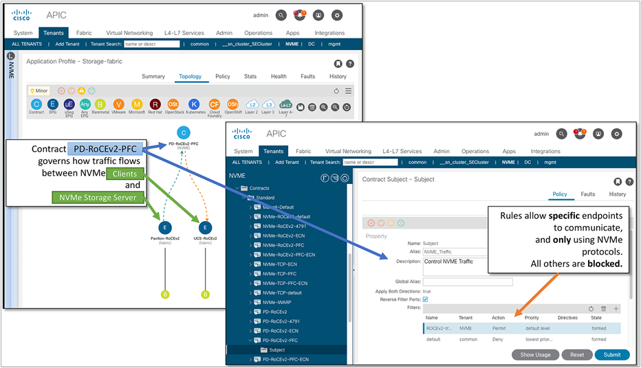
Network layer security comes from isolation and control. Cisco ACI tools allow the network manager to quickly create endpoint groups (such as storage servers and clients), and then apply strict traffic contracts to control the traffic between the endpoints. Without a contract, no traffic flows between the endpoints.
Networking challenge: performance
Network managers are already aware that storage systems put a stressful load on data center networks. Even with high-speed LAN-to-LAN communications within the data center, storage systems become the bottleneck for many compute environments – which is exactly why storage managers are upgrading to NVMe-based storage arrays.
In this section, we highlight some testing we have done with one NVMe storage array using 100 Gbps fabric and 100 Gbps inter-switch links. Our goal is not to show the performance of this particular product, but simply to show how performance varies in networks when these performance challenges are properly managed. We chose NVMe-oF with RoCEv2 because, as of this writing (early 2020), this is the most popular protocol in shipping NVMe storage systems. We hope to continue testing using NVMe-oF over TCP and NVMe-oF over iWARP as commercial products are released.
Handling the network stress of storage systems requires more than upgrading from 10Gb to 100Gb and 400Gb fabrics. Network managers need to turn the network into a more active participant in the storage subsystem, with careful topology design to minimize latency, advanced quality of service prioritization, and intelligent queue management.
| Performance management area |
Technique |
| Latency |
Use 100Gb device links, 400 Gb inter-switch links, spine-and-leaf topology, and ensure best performance with cut-through switches |
| Quality of Service (QoS) |
Priority Flow Control (IEEE 802.1Qbb) should be enabled to prevent packet loss due to congestion. When routing occurs, DSCP should be used to extend PFC signaling across Layer 3 networks. |
| Buffering |
Buffers on storage ports should be kept small. When intelligent buffering is available, as in Cisco Nexus 9000 Series Switches, these features should be enabled. |
Latency
Transaction response time in storage systems is one of the most important metrics for storage managers. The faster the answers come back, the faster the data center runs. In NVMe storage systems, most of the latency comes from the Solid State Disks (SSDs) themselves, and usually is in the range of 75 to 200 µsec.[4] Maintaining an ultra-low network latency – no more than 10 percent of the overall storage system latency – helps to ensure that storage managers see the performance they expect from these advanced high-speed SSD arrays. A good rule of thumb for intra-data center latency of NVMe-oF traffic would be to design for end-to-end latency of 10 µsec or less.[5]
Obviously, achieving low latency is simpler when there are 100 Gb NICs, 400 Gb inter-switch links, and fewer switches involved, which is why most latency-sensitive data centers have moved to a spine-and-leaf topology.[6] When inter-data center routing is anticipated, latency will grow, but should also be engineered to be as low as possible.
One of the first tools in the network manager’s toolbox to keep latency low and predictable, is fast switches with fast links. In the Cisco Nexus 9000 Series Switches, our testing showed overall latency across three switches averages less than 4 µsec, even at high link utilization with small packets. Figure 6 shows the results of testing a three-node Cisco Nexus 9000 configuration at 70 percent link utilization on 100 Gbps NICs and 100 Gbps inter-switch links with packet sizes from 128 to 9000 octets. Average latency across all four cases was in the range of 3.559 µsec to 3.617 µsec, benefitting from Cisco’s cut-through switching architecture and high-speed packet processors.
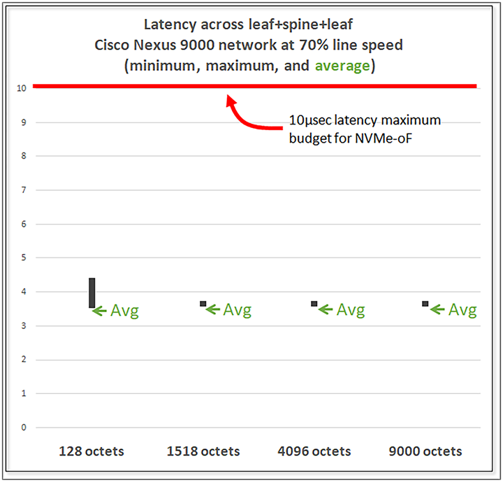
Testing shows that end-to-end latency across a three-node spine-and-leaf topology using 100 Gbps links is approximately 4 µsec at all packet sizes, well within the 10 µsec budget allowed for NVMe-oF.
Quality of Service and traffic prioritization
Network managers may be familiar with IEEE 802.3x Flow Control, a mechanism for switches to signal back to devices that buffers are full and traffic should be paused. In small homogeneous networks, simple flow control pauses an entire server while buffers empty out. However, when links carry different priorities of traffic – such as high priority storage mixed with lower priority data transfer, pausing all traffic on a link isn’t the right answer. This type of multi-traffic network is especially common in today’s highly virtualized data centers, where an entire chassis full of servers may attach to the network with only a few physical connections.
A newer technology, Priority Flow Control (PFC, defined in IEE 802.1Qbb), provides finer-grained flow control by allowing switches to pause an individual Class-of-Service (CoS) coming from a device. With Priority Flow Control (sometimes called Class-based Flow Control or Per Priority Pause), the Ethernet link is divided up into eight classes, and the switch can pause any class individually, rather than having to flow control the entire link.
PFC is an important technology for switches handling NVMe-oF traffic, especially those using “lossless” Ethernet, such as RoCEv2. By assigning different priorities to different classes and using PFC in the switch fabric, a network with long-term or microburst congestion will continue to pass storage traffic, avoiding loss and latency problems.
The benefits of PFC are easy to see when a network has even moderate levels of congestion. In the test shown below, we generated a read/write mix of traffic using Cisco UCS® clients and a popular NVMe storage system, running NVMe-oF with the RoCEv2 protocol. Our baseline test shows the network performance – about 70 Gbps – of our test. Then we added in competing traffic across the switch fabric to create network congestion at a level of roughly 125 percent of line speed (that is, 125 Gbps total storage plus competing traffic) and again at roughly 175 percent of line speed.
With no traffic management in place, overall storage system throughput dropped from 70 Gbps to less than 30 Gbps at 125 percent congestion – and the storage system failed completely at 175 percent congestion. However, when PFC was enabled, overall performance was barely affected – overall throughput dropped from 70.6 Gbps to 70.4 Gbps.
Because PFC is an Ethernet-layer flow control mechanism, it won’t automatically work in a routed network when passing Layer 3 boundaries. Network managers designing NVMe-oF networks that pass between data centers or through very large data centers can use the IP-layer DSCP (also called DiffServ) field as a way to maintain class-of-service by mapping Ethernet-layer PFC classes to IP-layer DSCP values.
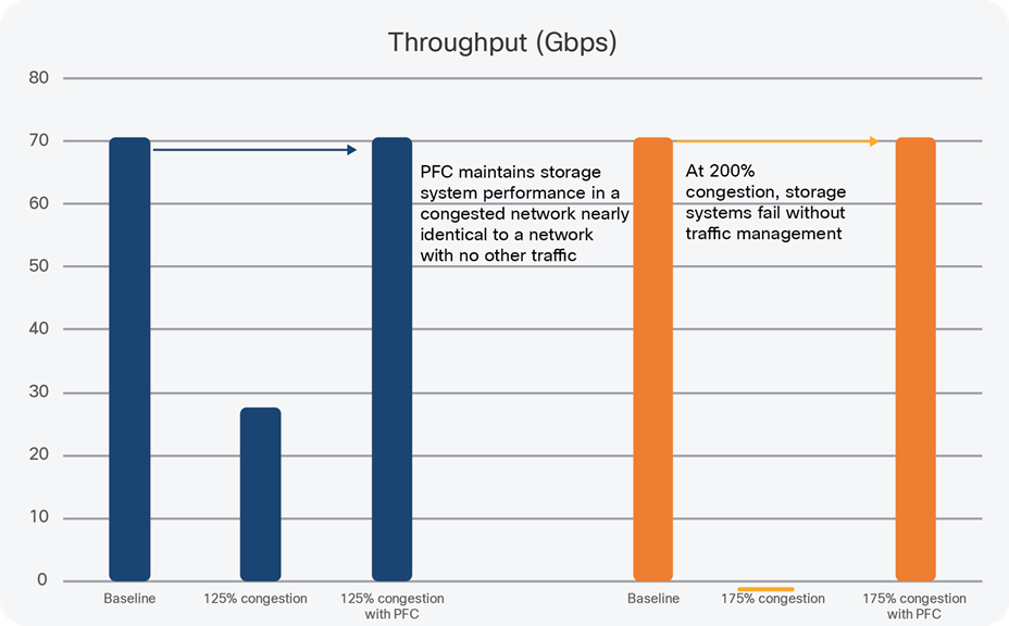
Traffic management is critical to maintain the performance of NVMe storage systems, even when congestion and oversubscription levels are moderate.
See Table 1 below
Table 1. Traffic management is critical to maintain the performance of NVMe storage systems, even when congestion and oversubscription levels are moderate.
| Scenario description |
Throughput |
Thousands of I/O per second (kIOPS) |
| Baseline – no congestion, NVMe/RoCEv2 |
70.6 Gbps |
2262 kIOPS |
| Add congestion; total bandwidth = 125% of line rate (NVMe/RoCEv2 + Congestion) |
27.8 Gbps |
892 kIOPS |
| Add congestion (125%) plus traffic engineering |
70.4 Gbps |
2225 kIOPS |
| Add congestion; total bandwidth = 200% of line rate |
0 – times out |
0 |
| Add congestion (200%) plus traffic engineering |
70.4 Gbps |
2253 kIOPS |
Intelligent queue and buffer management
In some networking environments, large buffers are a plus, as they help to smooth out bursts in traffic. However, in storage networks, large buffers can be a performance killer because of the delays that they introduce. In modern switches where a packet buffer can be tens of megabytes, buffering delays inside of switches can increase latency by three orders of magnitude or more. For example, with a common buffer size of 50 MB, a 10 Gb port could see a latency of up to 5000 µsec added if the buffer is not managed intelligently.
A full discussion of buffer management in switches would lengthen this white paper too much, so we’ll summarize by pointing out that most switches are designed to activate TCP’s congestion control mechanism, and use either Random Early Detection (RED) or Weighted RED (WRED) queue management to keep things moving smoothly and let TCP handle end-to-end congestion in the best way possible.[7] In data center networks where topologies are flat and protocols such as NVMe/RDMA are in use, this queue management strategy has an overall negative effect on storage system performance – the opposite of what is intended.
NVMe benefits from a queue management strategy that separates “elephant” flows and prioritizes “mice” flows to speed overall storage system performance. (Elephant flows are long-lived, transfer lots of data and aggressively us bandwidth; mice flows are short-lived control messages, but are very sensitive to latency and loss).
The difficulty for network managers is in classifying these different types of flows properly, and then programming switches to deliver appropriate queueing and buffer management for each type of flow. Some switches, such as the Cisco Nexus 9000 family, have built-in intelligent buffer management. With Cisco Dynamic Packet Prioritization (DPP) technology combined with innovative Approximate Fair Drop (AFD) queue management, the switch is responsible for identifying elephant and mice flows, separating them, and applying the appropriate queuing strategy during congestion.
Without DPP and AFD, storage sessions time out and reset during periods of high congestion, causing massive performance problems and application failure.
Networking challenge: monitoring
Network managers have been moving “up the stack” with tools such as NetFlow and sFlow to help in capacity planning and troubleshooting. Old-style SNMP counters such as “Input errors” became a thing of the past as Ethernet took over and these types of errors disappeared, and flow data have taken their place. Flow data are immensely useful to answer questions about bandwidth consumption, traffic directions, and application usage.
For storage networking, though, flow information is much too high-level. Instead, network managers need to move back down to the switching level, focusing on end-to-end performance between storage servers and storage clients. In this white paper, we’ve discussed the need to strictly control latency, to provide intelligent queuing for Converged Ethernet, and to maintain QoS and packet prioritization. Network managers need tools to provide visibility into the data center network to understand how storage traffic is flowing and whether it is meeting its requirements. NetFlow and sFlow won’t do the trick – they don’t have the end-to-end visibility needed, and the sampled nature of both protocols when operating at 100Gb (and higher) speeds means that critical issues can easily be missed.
In the Cisco Nexus 9000 Series Switches, Cisco has incorporated ASIC-based monitoring, using hardware-streaming technology to export information for analysis and reporting. Because Cisco Nexus 9000 Series Switches are IP-aware, even at Layer 2, as part of intelligent queue management, the IP 5-tuple metadata is already available for monitoring tools.
The screen captures below, from Cisco Network Insights Resources tool running on a 3-node cluster of UCS-based Application Service Engines, give examples of the kinds of statistics needed by a network manager trying to manage and maintain a network with high-speed NVMe-oF storage competing with other general purpose computing.
Because latency and packet drops are some of the most important end-to-end issues for data center networks, being able to quickly identify flows that have high latency or high drop rates is a first troubleshooting step. In the screen capture below (Figure 8), Network Insights has graphed the top flows for latency – nearly 400 µsec, way out of specification for NVMe-oF traffic, providing IP address and port information.
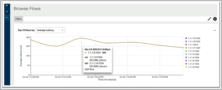
Network managers can quickly identify problem flows, such as this high latency one, using Network Insights tools that collect together end-to-end Ethernet latency information, combine it with IP and transport layer identifiers, and link to ACI endpoint labels, all on the same screen.
While a summary view that shows top flows is useful, being able to drill down to a single flow and see specific issues delivers the kind of specific information that a network manager needs to answer questions on network performance. In the screen capture below (Figure 9), a problematic flow with packet drops is highlighted. The network manager can see the physical topology the flow uses – which leaf and spine nodes are involved – as well as alerts based on Network Insights’s machine learning, such as a latency higher than the baseline.
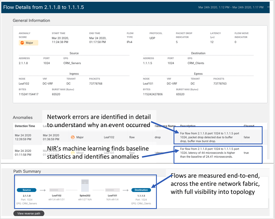
Network Insights combines machine learning, detailed switch error reporting, and network topology information together to give the network manager an immediate view into which flows are not performing properly, and where in the network to look for troubleshooting and problem resolution.
Network Insights also provides graphs for long-lived flows, such as those you’d find in an NVMe-oF storage environment, to help the network manager keep an eye on important statistics such as latency and packet drops.
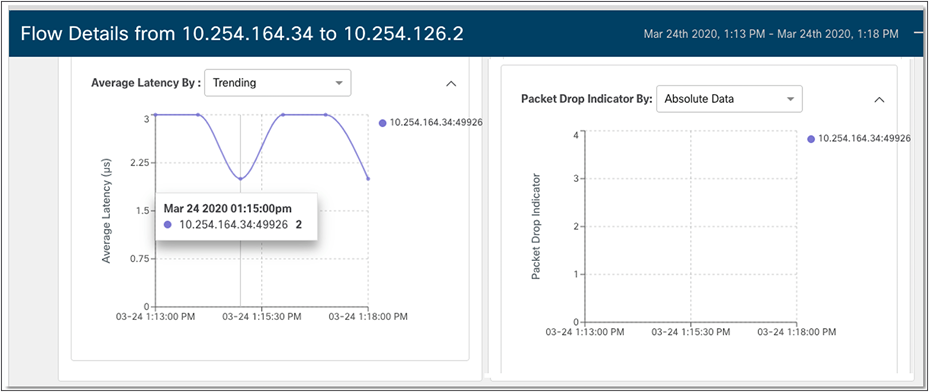
Statistics such as latency and lost packets are even more useful to the network manager when graphed over time to identify bursts or other abnormalities visually.
Networking challenge: management
As we’ve shown in this white paper, adding NVMe-oF storage to data center networks creates challenges for the network manager. A flexible network, kept secure, with carefully controlled performance and comprehensive monitoring: it’s a lot to ask, especially for network managers who may have chosen simpler configurations using simpler tools in the past.
A further complication in the world of storage is the need to have coordinated configurations when it comes to traffic engineering and Converged (lossless) Ethernet. When building this type of QoS into a network, the entire fabric has to be in sync so that paths from end to end are fully controlled. Network managers need to be able to confidently deploy configurations and deliver on Service Level Agreements (SLAs) to support demanding protocols such as NVMe/RoCEv2. And they need to do this without getting bogged down in the details of storage networking.
To give an idea of the scope of the problem, we created two configurations in Cisco Nexus 9000 Series Switches, using Cisco APIC.[8] Our starting configuration, covering three switches (two leaf and one spine), was the equivalent of 170 lines.[9] Then we added the configuration for our storage network – we defined the storage servers and clients (APIC “endpoint groups”), and we applied a policy (“contract” in APIC terminology) between the clients and servers that defined firewall rules and traffic engineering requirements. The resulting configuration was the equivalent of about 1050 lines, although the relevant details are easy to see in a single topology summary (see Figure 11 below).
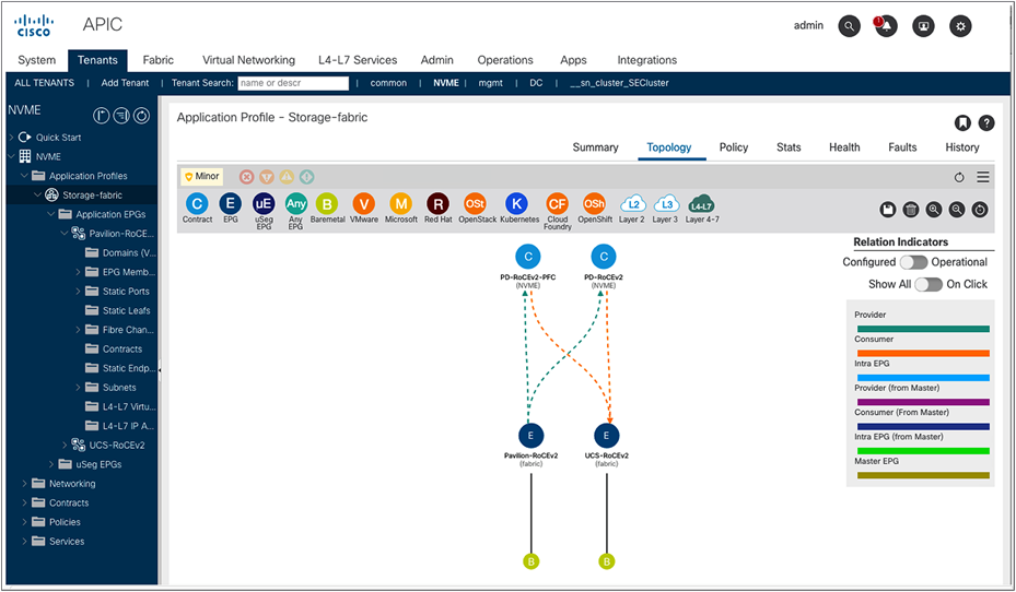
Visual representation of endpoint groups and their relationships helps the network manager quickly and accurately identify applications and apply the correct security and traffic engineering, across an entire network fabric. A thousand lines of traditional configuration are reduced to a few mouse clicks.
Network managers need to seek out network management tools that can automate deployment, provide accurate and complete configuration across an entire switch fabric, and are easy to use to minimize the chance of human error or misconfiguration.