Ascent of DSL with the Sunset of PSTN White Paper
Available Languages
Bias-Free Language
The documentation set for this product strives to use bias-free language. For the purposes of this documentation set, bias-free is defined as language that does not imply discrimination based on age, disability, gender, racial identity, ethnic identity, sexual orientation, socioeconomic status, and intersectionality. Exceptions may be present in the documentation due to language that is hardcoded in the user interfaces of the product software, language used based on RFP documentation, or language that is used by a referenced third-party product. Learn more about how Cisco is using Inclusive Language.
In today’s digital world, it is pivotal for networking devices to have connectivity to applications wherever they are located, in an enterprise data center or in the cloud. When deploying operational technologies in the field, device management, monitoring, and troubleshooting tools require operators to be able to reach devices remotely. Key to this operation is a reliable and secure communication link between the systems and the remote devices. This is the glue that binds the remote field devices to the business.
To meet this business need, Industrial Internet of Things (IoT) devices can leverage diverse wired and wireless WAN connectivity options such as Ethernet, DSL, PSTN, Wi-Fi, 4G, 5G, and LoRa. The cost, coverage, and infrastructure availability drive the choice of connectivity for each deployment scenario.
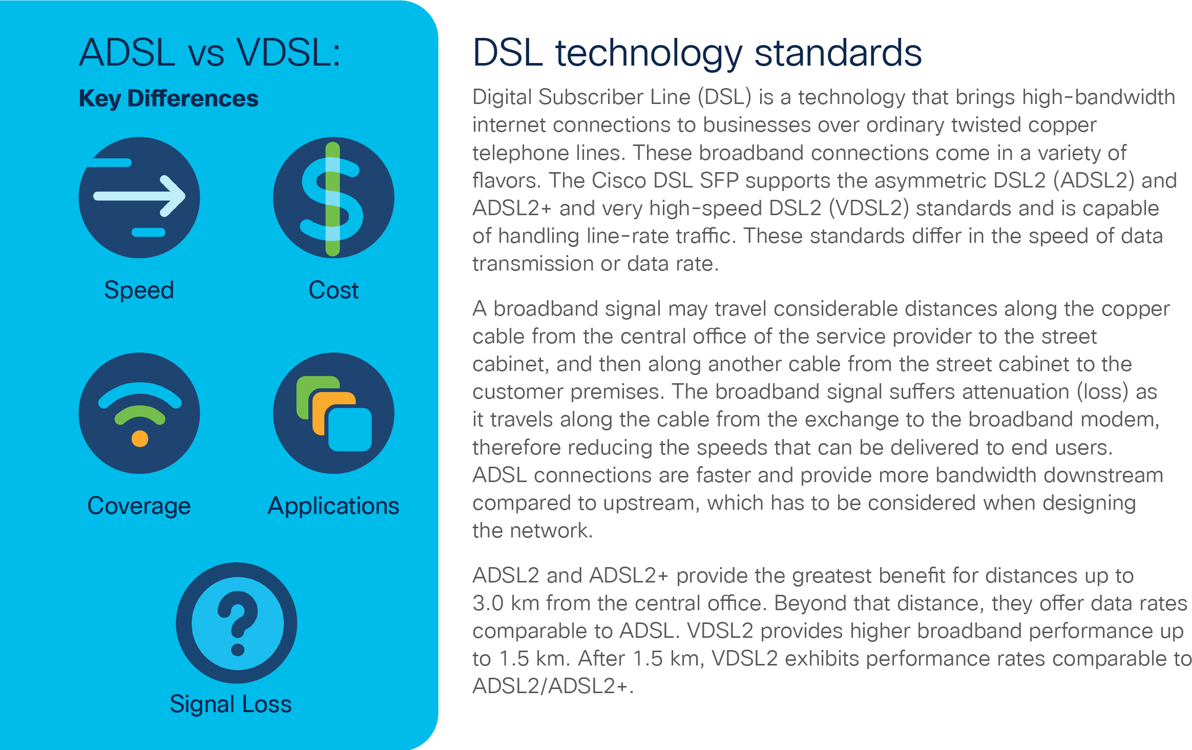
In Europe and the United Kingdom (UK), for remote locations the analog public switched telephone network (PSTN) has been the preferred deployment option until now, due to its cost-effectiveness and ubiquitous availability. With the sunsetting of PSTN, service providers are leveraging the existing copper network to provide digital forms of communication such as xDSL. These changes have triggered a recognition that businesses must take a leap into modern digital technologies for operational monitoring and control of their critical IoT networks.
Here are some key factors that are making the transition to xDSL attractive.
● High cost of operating older-generation systems
● Removal of legacy systems that are out of date and out of support
● A controlled transition from legacy equipment and services to new IP-enabled devices
● A latitude to enable new, higher-bandwidth security and supervisory control and data acquisition (SCADA) services without major disruption or reinvestment in communication capability
● An opportunity for a managed service, leading to less reliance on specialists and expensive in-house technical skills
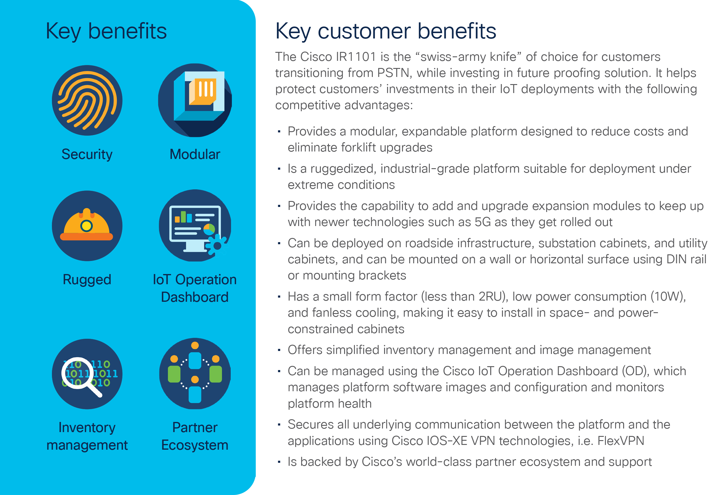
Cisco has been at the forefront of this transition and offers both cellular and wired options. We have introduced an xDSL Small Form-Factor Pluggable (SFP) module on the IR1101 to enable customers to migrate from PSTN to xDSL. The Cisco® 1101 Industrial Integrated Services Router (IR1101) offers 3G/4G/5G, fiber, and DSL uplinks through a single networking platform.
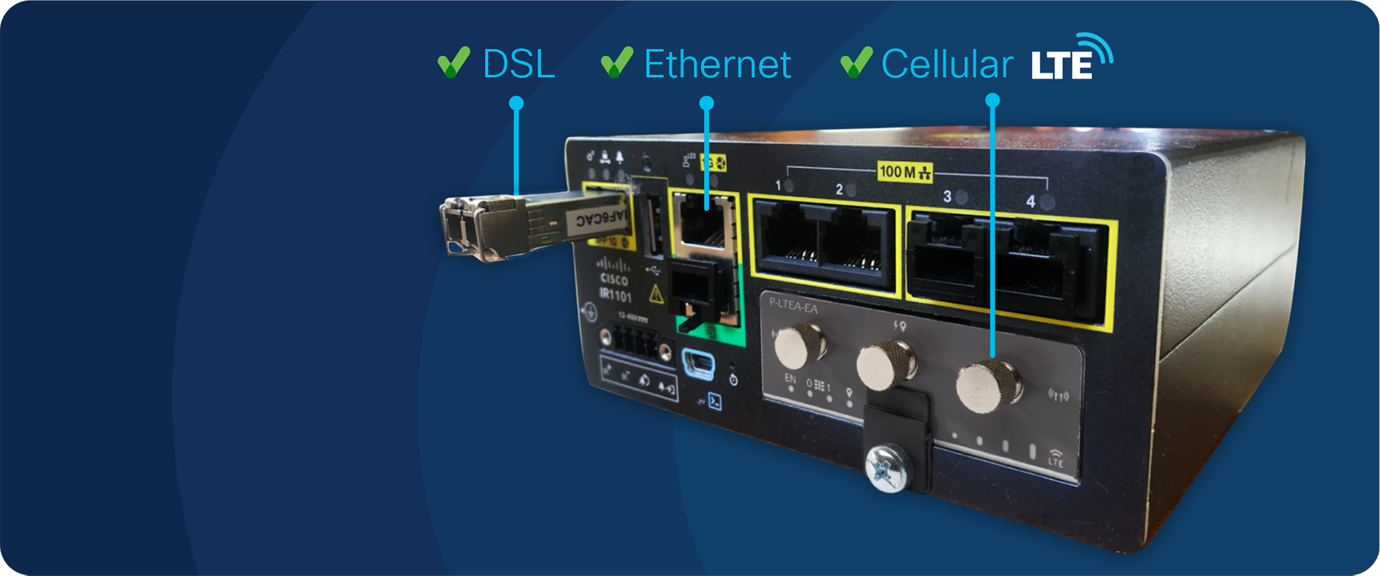
Cisco® IR1101 Integrated Services Router Rugged
Use cases for xDSL on IR1101
There are a variety of use cases in which xDSL is the WAN uplink of choice, here we will focus on the examples of roadside infrastructure and water management systems.
A public sector customer in the UK has one of the world’s biggest city transportation networks of road and rail routes. They adopted an adaptive signal control (ASC) system as a cost-effective way to manage traffic flow in real time based on prevailing conditions and traffic congestion.
An ASC technology known as the split-cycle offset optimization technique (SCOOT) adjusts the traffic signal timings in frequent, small increments based on real-time traffic demand. This system uses inductive loop or wireless vehicle detectors to monitor traffic. The telemetry data is streamed to a central system for traffic flow modelling. Based on the telemetry data from multiple locations, a central system calculates signal timing for splits, offset, and cycle length. The new timing is programmed back to the traffic signal in real time. The optimized traffic flow results in people spending less time in traffic.
The Cisco IR1101, located in a street-side cabinet, provides reliable, all-weather connectivity with DSL for primary data connectivity and a 4G LTE high-speed cellular data connection for secondary data connectivity. It provides high bandwidth link between traffic signal and central system which is used for bi-directional flow of telemetry info. This allows traffic signal intersections to be connected in a secure, reliable manner regardless of their location.
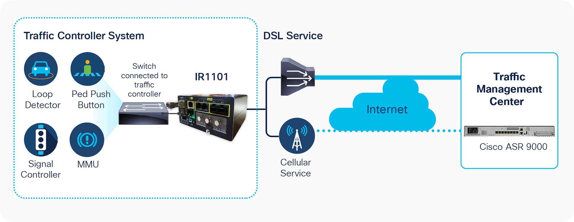
Traffic control system
A European utility enterprise customer manages a huge network of SCADA systems that provide water and sewage services for millions of customers. The water management is done through a SCADA system that uses hundreds of digital and analog sensors to monitor and regulate the flow of water, reservoir levels, and pipe pressure. These sensors are located at sewage pumping stations, reservoirs, water pumping stations, and water treatment plants. They measure data such as flow rate, valve pressure, and water levels in tanks.
They monitor and control assets are spread over 6000 remote locations. Key to this business is secure communication links between the systems and the remote devices. These links carry remote telemetry data for monitoring and control signals to automatically manage pump control systems.
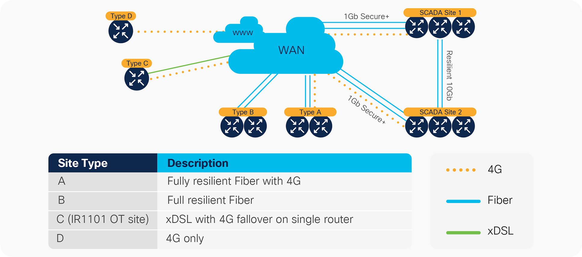
For remote location without cellular coverage the DSL technology was selected. For a fully fault-tolerant uplink WAN network, Cisco IR1101s at every site are connected to a service provider network via redundant ADSL2+/VSDL and 4G uplinks. Each data center has a pair of Cisco headend devices, for example Aggregation Service Router (ASR), Cloud Services Router (CSR) or Integrated Services Routers (ISR) with multiple virtual routing and forwarding instances (VRFs) configured. The connection between the IR1101 and head-end routers is secured with Cisco FlexVPN or other VPN technologies. In addition, strong security enforcement is performed to protect the connected devices and sites. This topology provides a secure and independent fault domain with no single point of failure.
Water management control system
| Hardware |
Description |
| IR1101-A-K9 |
Cisco IR1101 Integrated Services Router Rugged with SL-IR1101-NA software license |
| IR1101-K9 |
Cisco IR1101 Integrated Services Router Rugged with SL-IR1101-NE software license |
| SFP-VADSL2+-I |
DSL Cisco SFP option for Cisco IR1101 |
| SFP-VADSL2+-I= |
Spare DSL Cisco SFP option for Cisco IR1101 |
Learn more about Cisco® IR1101 Integrated Services Router.