Cisco ONS 15216 C L-Band Splitter/Combiner Module for Cisco ONS 15454 MSTP
Available Languages
DATA SHEET
The Cisco® ONS 15216 is an advanced C+L-band splitter/combiner module that provides service providers, system integrators, and network equipment manufacturers with one of the critical technologies needed to build high-capacity
2.5-, 10-, and 40-Gbps reconfigurable optical add/drop multiplexer (ROADM)-enabled DWDM networks.
Cisco DWDM systems deploying a maximum of thirty-two 100-GHz spaced channels in the C-band can be expanded to 64-channel capacity using the Cisco ONS 15216 C+L-Band Splitter/Combiner Module. The module can be deployed with the initial DWDM installation to make the DWDM system compatible with future versions and to avoid traffic downtime when the additional capacity is required. The module allows for a further 32-channel expansion into the L-band. To accomplish this upgrade a C+L-band splitter/combiner is required for multiplexing and demultiplexing the C and L bands. The Cisco ONS 15216 C+L-Band Splitter/Combiner Module incorporates a multiplexing section that combines the C and L bands into a composite signal for transmission over Cisco ONS 15454 Multiservice Transport Platform (MSTP) DWDM systems. The demultiplexer section splits the composite signal into the C and L band spectrums prior to further channel demultiplexing by the Cisco ONS 15454 MSTP ROADM.
The equipment is housed in a passive Cisco ONS 15216 FlexLayer module and mounted in the Cisco ONS 15216 FlexLayer 4-slot 1-rack-unit (RU) shelf unit. This module extracts a small part of the composite DWDM signal at the splitter and combiner for monitoring purposes. The module is completely (optical and electrical) passive.
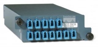
Figure 1
Cisco ONS 15216 C+L-Band Splitter/Combiner Module

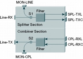
Figure 2 shows the Cisco ONS 15216 C+L-Band Splitter/Combiner Module optical flow. The unit is a bidirectional unit, in which the splitter function and the combiner function are implemented in two different sections so that signal flowing in opposite directions can be managed separately. The splitter section includes a tap coupler, allowing aggregate (C+OSC+L) received channels spectrum monitoring at the input (MON-LINE port), followed by a band-pass filter to split C-band plus optical supervisory channel (OSC) signals (SPL-TXC port) and the L-band signal (SPL-TXL port).
The combiner section includes a band-pass filter, to combine C-band plus OSC signals (CPL-RXC port) and the L-band signal (CPL-RXL port), followed by a tap coupler allowing aggregate (C+OSC+L) transmitted optical channels spectrum monitoring at the output (MON-CPL port).
Figure 2
Cisco ONS 15216 C+L-Band Splitter/Combiner Module Optical Schematic

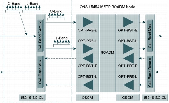
The Cisco ONS 15216 C+L-Band Splitter/Combiner Module is deployed with the Cisco ONS 15454 MSTP. In Figure 3 the module is deployed in Cisco ONS 15454 MSTP ROADM node.
Figure 3
Cisco ONS 15216 C+L-Band Splitter/Combiner Module Deployed in a Cisco ONS 15454 MSTP ROADM Node

PRODUCT ORDERING INFORMATION
Table 1 lists the ordering information for the Cisco ONS 15216 C+L-Band Splitter/Combiner Module.
Table 1. Ordering Information
To check prices and lead times, and to order products, go to:
http://www.cisco.com/en/US/ordering/index.shtml.
PRODUCT SPECIFICATIONS
Tables 2 and 3 list technical and environmental specifications for the Cisco ONS 15216 C+L-Band Splitter/Combiner Module. Table 4 provides port information.
Table 2. Technical Specifications
All the Insertion Loss values have to be measured as the maximum insertion loss inside the Total (C + OSC) Optical Bandwidth.
2 All the Insertion Loss values have to be measured as the maximum insertion loss inside the Total L Optical Bandwidth.
3 All the Insertion Loss values have to be measured as the maximum insertion loss inside the Total Optical Bandwidth (C + OSC band and L band).
Table 3. Environmental Performance
| Item |
Condition |
MIN |
MAX |
Units |
| Operating Temperature |
|
-5 |
65 |
°C |
| Storage Temperature |
|
-40 |
85 |
°C |
| Operating Humidity |
|
5 |
95 |
%RH |
| Storage Humidity |
|
5 |
95 |
%RH |
Table 4. Port Naming and Labeling
 Feedback