Deploy Microsoft SQL Server 2019 with Hyper-V on
Cisco HyperFlex All-Flash System with NVMe Cache Drive
Available Languages
Bias-Free Language
The documentation set for this product strives to use bias-free language. For the purposes of this documentation set, bias-free is defined as language that does not imply discrimination based on age, disability, gender, racial identity, ethnic identity, sexual orientation, socioeconomic status, and intersectionality. Exceptions may be present in the documentation due to language that is hardcoded in the user interfaces of the product software, language used based on RFP documentation, or language that is used by a referenced third-party product. Learn more about how Cisco is using Inclusive Language.
Cisco HyperFlex™ systems deliver complete hyperconvergence, combining software-defined networking and computing with the next-generation Cisco HyperFlex HX Data Platform. Engineered on the Cisco Unified Computing System™ (Cisco UCS®), Cisco HyperFlex systems deliver the operational requirements for agility, scalability, and pay-as-you-grow economics of the cloud—with the benefits of on-premises infrastructure. With hybrid or all-flash-memory storage configurations and a choice of management tools, Cisco HyperFlex systems deliver a preintegrated cluster with a unified pool of resources that you can quickly deploy, adapt, scale, and manage to efficiently power your applications and your business.
With the latest all-flash storage configurations, a low-latency, high-performing hyperconverged storage platform is now a reality. Such a storage platform is optimal for hosting latency-sensitive applications such as Microsoft SQL Server. This document provides guidelines for deploying a Microsoft SQL Server virtual machine setup on an all-flash Cisco HyperFlex storage platform.
This document is intended for system administrators, database specialists, and storage architects who are planning, designing, or implementing a Microsoft SQL Server database on a Cisco HyperFlex all-flash storage solution.
This document discusses a reference architecture and provides implementation guidelines for deploying Microsoft SQL Server 2019 database instances on a Cisco HyperFlex all-flash solution with a Non-Volatile Memory Express (NVMe) cache drive.
This section provides an overview of the technology used in the Cisco HyperFlex all-flash and Microsoft SQL Server solution described in this document.
Cisco HyperFlex HX Data Platform
Cisco HyperFlex systems are designed with an end-to-end software-defined infrastructure that eliminates the compromises found in first-generation products. Cisco HyperFlex systems combine software-defined computing in the form of Cisco UCS servers, software-defined storage with the powerful Cisco HyperFlex HX Data Platform software, and software-defined networking (SDN) with the Cisco® unified fabric that integrates smoothly with Cisco Application Centric Infrastructure (Cisco ACI™). With all-flash memory storage configurations and a choice of management tools, Cisco HyperFlex systems deliver a preintegrated cluster that is up and running in an hour or less and that scales resources independently to closely match your application resource needs (Figure 1. ).
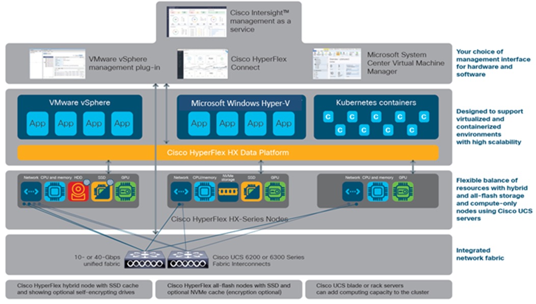
Cisco HyperFlex systems offer next-generation hyperconverged solutions
The all-flash Cisco HyperFlex HX Data Platform includes these features:
● Enterprise-class data management features provide the complete lifecycle management and enhanced data protection required in distributed storage environments. These features include replication, always-on inline deduplication, always-on inline compression, thin provisioning, instantaneous space efficient clones, and snapshots.
● Simplified data management integrates storage functions into existing management tools, allowing instant provisioning, cloning, and pointer-based snapshots of applications for dramatically simplified daily operations.
● Improved control with advanced automation and orchestration capabilities, robust reporting, and analytics features deliver improved visibility and insight into IT operation.
● Independent scaling of the computing and capacity tiers gives you the flexibility to scale out the environment based on evolving business needs for predictable, pay-as-you-grow efficiency. As you add resources, data is automatically rebalanced across the cluster, without disruption, to take advantage of the new resources.
● Continuous data optimization with inline data deduplication and compression increases resource utilization with more headroom for data scaling.
● Dynamic data placement optimizes performance and resilience by enabling all cluster resources to participate in I/O responsiveness. All-flash nodes use solid-state disk (SSD) and NVMe drives for the caching layer and SSDs for the capacity layer. This approach helps eliminate storage hotspots and makes the performance capabilities of the cluster available to every virtual machine. If a drive fails, reconstruction can proceed quickly because the aggregate bandwidth of the remaining components in the cluster can be used to access data.
● Enterprise data protection with a highly-available, self-healing architecture supports nondisruptive, rolling upgrades and offers call-home and onsite 24x7 support options.
● API-based data platform architecture provides data virtualization flexibility to support existing and new cloud-native data types.
In Cisco HyperFlex systems, the data platform spans three or more Cisco HyperFlex HX-Series nodes to create a highly available cluster. Each node includes a Cisco HyperFlex HX Data Platform controller that implements the scale-out and distributed file system using internal flash-based SSD and NVMe storage, or a combination of flash-based SSDs and high-capacity hard-disk drives (HDDs) to store data.
The controllers communicate with each other over 10 or 40 Gigabit Ethernet to present a single pool of storage that spans the nodes in the cluster (Figure 2. ). Nodes access data through a data layer using file, block, object, and API plug-ins. As nodes are added, the cluster scales linearly to deliver computing, storage capacity, and I/O performance.
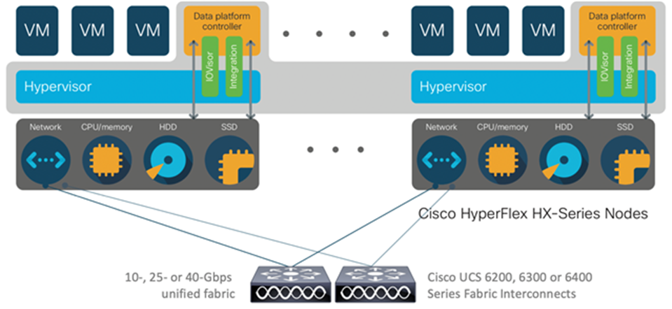
Distributed Cisco HyperFlex system
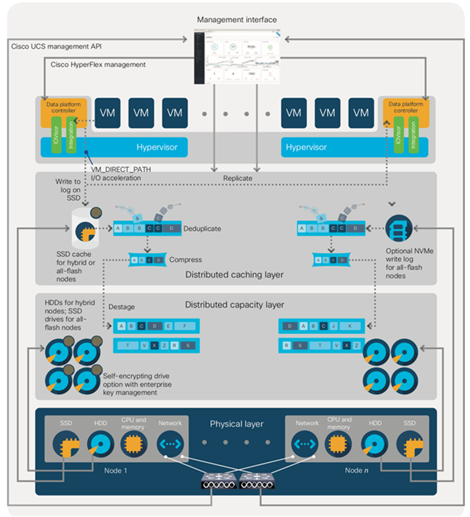
A Cisco HyperFlex HX Data Platform controller resides on each node and implements a distributed file system. The controller runs in user space within a virtual machine and intercepts and handles all I/O from guest virtual machines. Dedicated CPU cores and memory allow the controller to deliver consistent performance without affecting performance of the other virtual machines in the cluster. The data platform has modules to support the specific hypervisor or container platform in use. The controller accesses all of the node’s disk storage through hypervisor bypass mechanisms (the Discrete Device Assignment feature was introduced in Windows Server 2016) for excellent performance. It uses the node’s memory and dedicated SSD and NVMe drives as part of a distributed caching layer, and it uses the node’s other SSD drives, for distributed storage. The data platform controller interfaces with the hypervisor in two ways:
● IO Visor: The data platform controller intercepts all I/O requests and routes them to the nodes responsible for storing or retrieving the blocks. IO Visor makes the existence of the hyperconvergence layer transparent to the hypervisor.
● Advanced feature integration: A module uses the hypervisor APIs to support advanced storage system operations such as snapshots and cloning. These are accessed through the hypervisor so that the hyperconvergence layer appears as if it were enterprise-shared storage. The controller accelerates operations by manipulating metadata rather than actual data copying, providing rapid response, and thus rapid deployment of new application environments.
Figure 3. illustrates the storage controller virtual machine architecture, showing the I/O path for Cisco HyperFlex systems with Microsoft Hyper-V.
Cisco HyperFlex data fabric for Microsoft Hyper-V
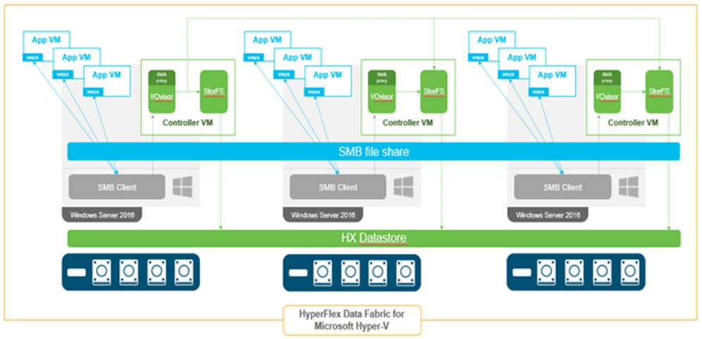
Storage controller virtual machine architecture for Cisco HyperFlex systems on Microsoft Hyper-V
Cisco HyperFlex system details
Engineered on the successful Cisco UCS platform, Cisco HyperFlex systems deliver a hyperconverged solution that truly integrates all components in the data center infrastructure: computing, storage, and networking. The HX Data Platform starts with three or more nodes to form a highly available cluster. Each of these nodes has a software controller called the Cisco HyperFlex controller. It takes control of the internal flash-based SSDs or a combination of flash-based SSDs and HDDs to store persistent data in a single distributed, multitier, object-based datastore. The controllers communicate with each other over low-latency 10 or 40 Gigabit Ethernet fabric, to present a single pool of storage that spans all the nodes in the cluster so that data availability is not affected if a single or multiple components fail.
The HX Data Platform controller handles all read and write requests for volumes that the hypervisor accesses, and thus intermediates all I/O from the virtual machines and containers. Recognizing the importance of data distribution, the HX Data Platform is designed to exploit low network latencies and parallelism, in contrast to other approaches that build on node-local affinity and can easily cause data hotspots.
With data distribution, the data platform stripes data evenly across all nodes, with the number of data replicas determined by the policies you set (Figure 3. 4). This approach helps prevent both network and storage hotspots and makes I/O performance the same regardless of virtual machine location. This feature gives you more flexibility in workload placement and contrasts with other architectures in which a data locality approach does not fully utilize all available networking and I/O resources.
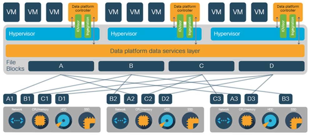
Data blocks are replicated across the cluster
● Data write operations: For write operations, data is written to the local SSD or NVMe cache, and the replicas are written to remote caches in parallel before the write operation is acknowledged. Write operations are later synchronously flushed to the capacity-layer HDDs (for hybrid nodes) or SSD drives (for all-flash nodes) or NVMe storage (for NVMe nodes).
● Data read operations: For read operations in all-flash nodes, local and remote data is read directly from storage in the distributed capacity layer. For read operations in hybrid configurations, data that is local usually is read directly from the cache. This process allows the platform to use all solid-state storage for read operations, reducing bottlenecks and delivering excellent performance. In addition, when migrating a virtual machine to a new location, the data platform does not require data movement because any virtual machine can read its data from any location. Thus, moving virtual machines has no performance impact or cost.
In addition, when a virtual machine migrates to a new location, the data platform does not require data movement because any virtual machine can read its data from any location. Thus, moving virtual machines has no performance impact or cost.
The data platform implements a distributed, log-structured file system that changes the way it handles caching and storage capacity depending on the node configuration.
In the all-flash-memory configuration, the data platform uses a caching layer in SSDs to accelerate write responses, and it implements the capacity layer in SSDs. Read requests are fulfilled directly from data obtained from the SSDs in the capacity layer. A dedicated read cache is not required to accelerate read operations.
Incoming data is striped across the number of nodes required to satisfy availability requirements—usually two or three nodes. Based on policies you set, incoming write operations are acknowledged as persistent after they are replicated to the SSD drives in other nodes in the cluster. This approach reduces the likelihood of data loss due to SSD or node failures. The write operations are then destaged to SSDs in the capacity layer in the all-flash memory configuration for long-term storage.
The log-structured file system writes sequentially to one of two write logs (three in the case of a replication factor of 3 [RF3]) until it is full. It then switches to the other write log while destaging data from the first to the capacity tier. When existing data is (logically) overwritten, the log-structured approach simply appends a new block and updates the metadata. This layout benefits SSD configurations in which seek operations are not time consuming. It reduces the write amplification levels of SSDs and the total number of write operations the flash media experiences due to incoming write and random overwrite operations of the data.
When data is destaged to the capacity tier in each node, the data is deduplicated and compressed. This process occurs after the write operation is acknowledged, so no performance penalty is incurred for these operations. A small deduplication block size helps increase the deduplication rate. Compression further reduces the data footprint. Data is then moved to the capacity tier as write cache segments are released for reuse (Figure 5. ).
Read operations in hybrid nodes cache data on the SSD drives and in main memory for high performance. In all-flash and NVMe nodes, they read directly from storage. Having the most frequently used data stored in the caching layer helps make Cisco HyperFlex systems perform well for virtualized applications. When virtual machines modify data, the original block is likely read from the cache, so there is often no need to read and then expand the data on a spinning disk. The data platform decouples the caching tier from the capacity tier and allows independent scaling of I/O performance and storage capacity.
Data write operation flow through the Cisco HyperFlex HX Data Platform
The Cisco HyperFlex HX Data Platform provides finely detailed inline deduplication and variable block inline compression that is always on for objects in the cache (SSD and NVMe drives and memory) and capacity (SSD or HDD) layers. Unlike other solutions, which require you to turn off these features to maintain performance, the deduplication and compression capabilities in the Cisco data platform are designed to sustain and enhance performance and significantly reduce physical storage capacity requirements.
Data deduplication is used on all storage in the cluster, including memory and SSD drives. Based on a patent-pending Top-K Majority algorithm, the platform uses conclusions from empirical research that show that most data, when sliced into small data blocks, has significant deduplication potential based on a minority of the data blocks. By fingerprinting and indexing just these frequently used blocks, high rates of deduplication can be achieved with only a small amount of memory, which is a high-value resource in cluster nodes (Figure 6. ).
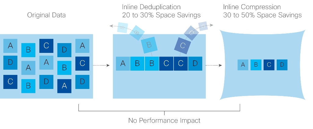
Cisco HyperFlex HX Data Platform optimizes data storage with no performance impact
The Cisco HyperFlex HX Data Platform uses high-performance inline compression on data sets to save storage capacity. Although other products offer compression capabilities, many negatively affect performance. In contrast, the Cisco data platform uses CPU-offload instructions to reduce the performance impact of compression operations. In addition, the log-structured distributed-objects layer has no effect on modifications (write operations) to previously compressed data. Instead, incoming modifications are compressed and written to a new location, and the existing (old) data is marked for deletion, unless the data needs to be retained in a snapshot.
The data that is being modified does not need to be read prior to the write operation. This feature avoids typical read-modify-write penalties and significantly improves write performance.
Log-structured distributed objects
In the Cisco HyperFlex HX Data Platform, the log-structured distributed-object store layer groups and compresses data that filters through the deduplication engine into self-addressable objects. These objects are written to disk in a log-structured, sequential manner. All incoming I/O—including random I/O—is written sequentially to both the caching (SSD and memory) and persistent (SSD or HDD) tiers. The objects are distributed across all nodes in the cluster to make uniform use of storage capacity.
By using a sequential layout, the platform helps increase flash-memory endurance. Because read-modify-write operations are not used, compression, snapshot operations, and cloning have little or no impact on overall performance.
Data blocks are compressed into objects and sequentially laid out in fixed-size segments, which in turn are sequentially laid out in a log-structured manner (0). Each compressed object in the log-structured segment is uniquely addressable using a key, with each key fingerprinted and stored with a checksum to provide a high level of data integrity. In addition, the chronological writing of objects helps the platform quickly recover from media or node failures by rewriting only the data that came into the system after it was truncated due to a failure.
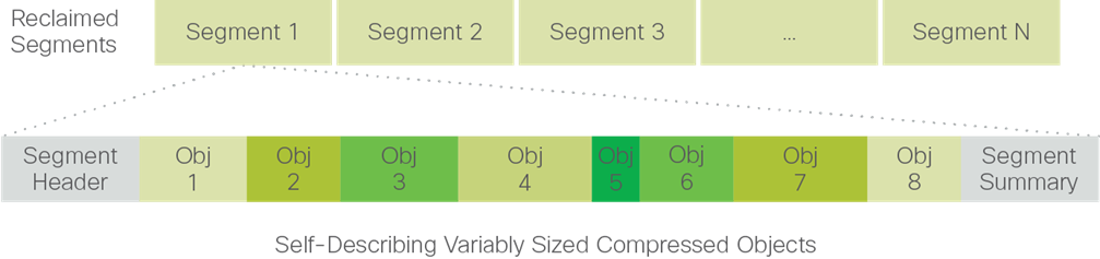
Cisco HyperFlex HX Data Platform optimizes data storage with no performance impact
Encryption
Securely encrypted storage optionally encrypts both the caching and persistent layers of the data platform. Integrated with enterprise key management software, or with passphrase-protected keys, encryption of data at rest helps you comply with Health Insurance Portability and Accountability Act (HIPAA), Payment Card Industry Data Security Standard (PCI-DSS), Federal Information Security Management Act (FISMA), and Sarbanes-Oxley (SOX) regulations. The platform itself is hardened to Federal Information Processing Standard (FIPS) 140-1, and the encrypted drives with key management comply with the FIPS 140-2 standard.
The Cisco HyperFlex HX Data Platform provides a scalable implementation of space-efficient data services, including thin provisioning, space reclamation, pointer-based snapshots, and clones—without affecting performance.
The platform makes efficient use of storage by eliminating the need to forecast, purchase, and install disk capacity that may remain unused for a long time. Virtual data containers can present any amount of logical space to applications, whereas the amount of physical storage space that is needed is determined by the data that is written. You can expand storage on existing nodes and expand your cluster by adding more storage-intensive nodes as your business requirements dictate, eliminating the need to purchase large amounts of storage before you need it.
In the Cisco HyperFlex HX Data Platform, clones are writable snapshots that can be used to rapidly provision items such as virtual desktops and applications for test and development environments. These fast, space-efficient clones rapidly replicate storage volumes so that virtual machines can be replicated through just metadata operations, with actual data copying performed only for write operations. With this approach, hundreds of clones can be created and deleted in minutes. Compared to full-copy methods, this approach can save a significant amount of time, increase IT agility, and improve IT productivity.
Clones are deduplicated when they are created. When clones start diverging from one another, data that is common between them is shared, with only unique data occupying new storage space. The deduplication engine eliminates data duplicates in the diverged clones to reduce the clone’s storage footprint.
Data replication and availability
In the Cisco HyperFlex HX Data Platform, the log-structured distributed-object layer replicates incoming data, improving data availability. Based on policies that you set, data that is written to the write cache is synchronously replicated to one or two other SSDs drives located in different nodes before the write operation is acknowledged to the application. This approach allows incoming writes to be acknowledged quickly while protecting data from SSD or node failures. If an SSD or node fails, the replica is quickly re-created on other SSD drives or nodes using the available copies of the data.
The log-structured distributed-object layer also replicates data that is moved from the write cache to the capacity layer. This replicated data is likewise protected from SSD or node failures. With two replicas, or three data copies, the cluster can survive uncorrelated failures of two SSD drives or two nodes without the risk of data loss. Uncorrelated failures are failures that occur on different physical nodes. Failures that occur on the same node affect the same copy of data and are treated as a single failure. For example, if one disk in a node fails and subsequently another disk on the same node fails, these correlated failures count as one failure in the system. In this case, the cluster could withstand another uncorrelated failure on a different node. See the Cisco HyperFlex HX Data Platform system administrator’s guide for a complete list of fault-tolerant configurations and settings.
If a problem occurs in the Cisco HyperFlex HX controller software, data requests from the applications residing in that node are automatically routed to other controllers in the cluster. This same capability can be used to upgrade or perform maintenance on the controller software on a rolling basis without affecting the availability of the cluster or data. This self-healing capability is one of the reasons that the Cisco HyperFlex HX Data Platform is well suited for production applications.
A distributed file system requires a robust data rebalancing capability. In the Cisco HyperFlex HX Data Platform, no overhead is associated with metadata access, and rebalancing is extremely efficient. Rebalancing is a nondisruptive online process that occurs in both the caching and persistent layers, and data is moved at a fine level of specificity to improve the use of storage capacity. The platform automatically rebalances existing data when nodes and drives are added or removed or when they fail. When a new node is added to the cluster, its capacity and performance is made available to new and existing data. The rebalancing engine distributes existing data to the new node and helps ensure that all nodes in the cluster are used uniformly from capacity and performance perspectives. If a node fails or is removed from the cluster, the rebalancing engine rebuilds and distributes copies of the data from the failed or removed node to available nodes in the clusters.
Cisco HyperFlex HX-Series nodes and the HX Data Platform support online upgrades so that you can expand and update your environment without business disruption. You can easily expand your physical resources; add processing capacity; and download and install BIOS, driver, hypervisor, firmware, and Cisco UCS Manager updates, enhancements, and bug fixes.
This section discusses the Cisco UCS and Cisco HyperFlex physical infrastructure used in the solution discussed in this document.
Cisco Unified Computing System
Cisco UCS consists of the following main components:
● Computing: The system is based on an entirely new class of computing system that incorporates rack-mount and blade servers based on Intel® Xeon® processors.
● Network: The system is integrated onto a low-latency, lossless, 10-, 25-, or 40-Gbps unified network fabric. This network foundation consolidates LANs, SANs, and high-performance computing networks, which are often separate networks today. The unified fabric lowers costs by reducing the number of network adapters, switches, and cables, and by decreasing power and cooling requirements.
● Virtualization: The system unleashes the full potential of virtualization by enhancing the scalability, performance, and operational control of virtual environments. Cisco security, policy enforcement, and diagnostic features are now extended into virtualized environments to better support changing business and IT requirements.
● Storage access: The system provides consolidated access to both SAN storage and network-attached storage (NAS) over the unified fabric. By unifying storage access, Cisco UCS can access storage over Ethernet, Fibre Channel, Fibre Channel over Ethernet (FCoE), and Small Computer System Interface over IP (iSCSI) connections. This approach provides customers with their choice of storage protocol and physical architecture as well as enhanced investment protection. In addition, server administrators can pre-assign storage-access policies for system connectivity to storage resources, simplifying storage connectivity and management for increased productivity.
● Management: The system uniquely integrates all system components, which enables the entire solution to be managed as a single entity by Cisco UCS Manager. Cisco UCS Manager has an intuitive GUI, a command-line interface (CLI), and a robust API to manage all system configuration and operations.
Cisco UCS is designed to deliver these benefits:
● Reduced TCO and increased business agility
● Increased IT staff productivity through just-in-time provisioning and mobility support
● A cohesive, integrated system that unifies the technology in the data center; the system is managed, serviced, and tested as a whole
● Scalability through a design for hundreds of discrete servers and thousands of virtual machines and the capability to scale I/O bandwidth to match demand
● Industry standards supported by a partner ecosystem of industry leaders
Cisco UCS fabric interconnects
The Cisco UCS fabric interconnect is a core part of Cisco UCS, providing both network connectivity and management capabilities for the system. Depending on the model chosen, the Cisco UCS fabric interconnect offers line-rate, low-latency, lossless 10 or 40 Gigabit Ethernet, FCoE, and Fibre Channel connectivity. Cisco UCS fabric interconnects provide the management and communication backbone for the Cisco UCS C-Series Rack Servers, S-Series Storage Servers, and B-Series Blade Servers; Cisco HyperFlex HX-Series rack-mount servers; and Cisco UCS 5100 Series Blade Server Chassis. All servers and chassis, and therefore all blades, attached to the Cisco UCS fabric interconnects become part of a single, highly available management domain. In addition, by supporting unified fabrics, fabric interconnects provide both the LAN and SAN connectivity for all servers within a domain.
From a networking perspective, the Cisco UCS 6200 Series Fabric Interconnects use a cut-through architecture, supporting deterministic, low-latency, line-rate 10 Gigabit Ethernet on all ports, up to 1.92 Tbps of switching capacity, and 160 Gbps of bandwidth per chassis, independent of packet size and enabled services. The product family supports Cisco low-latency, lossless 10 Gigabit Ethernet unified network fabric capabilities, which increase the reliability, efficiency, and scalability of Ethernet networks. Fabric interconnects support multiple traffic classes over the Ethernet fabric from the servers to the uplinks. Significant TCO savings are achieved through an FCoE-optimized server design in which network interface cards (NICs), host bus adapters (HBAs), cables, and switches can be consolidated.
The Cisco UCS 6300 Series Fabric Interconnects offer the same features as the 6200 Series while enabling even higher performance. The 6300 Series supports low-latency, lossless, line-rate 40 Gigabit Ethernet, with up to 2.56 Tbps of switching capacity. Backward compatibility and scalability are assured with the capability to configure 40-Gbps Quad Small Form-Factor Pluggable SFP (QSFP) ports as breakout ports using four 10 Gigabit Ethernet breakout cables. Existing Cisco UCS servers with 10 Gigabit Ethernet interfaces can be connected in this manner, although Cisco HyperFlex nodes must use a 40 Gigabit Ethernet virtual interface card (VIC) adapter to connect to a Cisco UCS 6300 Series Fabric Interconnect.
The Cisco UCS 6454 Fabric Interconnect uses a cut-through architecture, supporting deterministic, low-latency, line-rate 10, 25, 40, and 100 Gigabit Ethernet ports, a switching capacity of 3.82 Tbps, and 320 Gbps of bandwidth between the 6454 Fabric Interconnect and the Cisco UCS 2208 Fabric Extender per 5108 Blade Server Chassis, independent of packet size and enabled services. The product family supports Cisco low-latency, lossless 10, 25, 40, and 100 Gigabit Ethernet unified network fabric capabilities, which increase the reliability, efficiency, and scalability of Ethernet networks. The fabric interconnect supports multiple traffic classes over a lossless Ethernet fabric from the server through the fabric interconnect.
The Cisco UCS fabric interconnects listed here are supported by Cisco HyperFlex systems. For detailed information about these fabric interconnects, see Cisco UCS Fabric Interconnects and Fabric Extenders.
● Cisco UCS 6248UP 48-Port Fabric Interconnect
● Cisco UCS 6296UP 96-Port Fabric Interconnect
● Cisco UCS 6332 Fabric Interconnect
● Cisco UCS 6332-16UP Fabric Interconnect
● Cisco UCS 6454 Fabric Interconnect
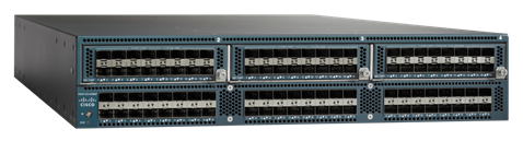
Cisco UCS 6248UP 48-Port Fabric Interconnect
The Cisco UCS 6248UP 48-Port Fabric Interconnect (Figure 8) is a 1-rack-unit (1RU) 10 Gigabit Ethernet, FCoE, and Fibre Channel switch offering up to 960 Gbps of throughput and up to 48 ports. The switch has 32 x 1- and 10-Gbps fixed Ethernet and FCoE or 1-, 2-, 4-, and 8-Gbps Fibre Channel ports, plus 1 expansion slot.
Cisco UCS 6248UP 48-Port Fabric Interconnect
Cisco UCS 6296UP 96-Port Fabric Interconnect
The Cisco UCS 6296UP 96-Port Fabric Interconnect (Figure 9) is a 2RU 10 Gigabit Ethernet, FCoE, and native Fibre Channel switch offering up to 1920 Gbps of throughput and up to 96 ports. The switch has 48 x 1- and 10-Gbps fixed Ethernet and FCoE or 1-, 2-, 4-, and 8-Gbps Fibre Channel ports, plus 3 expansion slots.
Cisco UCS 6296UP 96-Port Fabric Interconnect
Cisco UCS 6332 Fabric Interconnect
The Cisco UCS 6332 Fabric Interconnect (Figure 10) is a 1RU 40 Gigabit Ethernet and FCoE switch offering up to 2560 Gbps of throughput. The switch has 32 x 40-Gbps fixed Ethernet and FCoE ports. Up to 24 of the ports can be reconfigured as 4 x 10-Gbps breakout ports, providing up to 96 x 10-Gbps ports.
Cisco UCS 6332 Fabric Interconnect
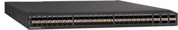
Cisco UCS 6332-16UP Fabric Interconnect
The Cisco UCS 6332-16UP Fabric Interconnect (Figure 11) is a 1RU 10 and 40 Gigabit Ethernet, FCoE, and native Fibre Channel switch offering up to 2430 Gbps of throughput. The switch has 24 x 40-Gbps fixed Ethernet and FCoE ports, plus 16 x 1- and 10-Gbps fixed Ethernet and FCoE or 4-, 8-, and 16-Gbps Fibre Channel ports. Up to 18 of the 40-Gbps ports can be reconfigured as 4 x 10-Gbps breakout ports, providing up to 88 total 10-Gbps ports.
Cisco UCS 6332-16UP Fabric Interconnect
Note: When used for a Cisco HyperFlex deployment, because of mandatory quality-of-service (QoS) settings in the configuration, the Cisco UCS 6332 and 6332-16UP Fabric Interconnects are limited to a maximum of 4 x 10-Gbps breakout ports, which can be used for servers other than Cisco HyperFlex servers.
Cisco UCS 6454 Fabric Interconnect
The Cisco UCS 6454 Fabric Interconnect (Figure 12) is a 1RU 10-, 25-, 40, and 100- Gbps Ethernet, FCoE and Fibre Channel switch offering up to 3.82 Tbps of throughput and up to 54 ports. The switch has 36 x 10 and 25 Gigabit Ethernet ports, 4 x 1, 10, and 25 Gigabit Ethernet ports, 6 x 40 and 100 Gigabit Ethernet uplink ports, and 8 unified ports that can support 8 x 10- and 25-Gbps Ethernet or 8-, 16-, and 32-Gbps Fibre Channel. All Ethernet ports are capable of supporting FCoE.
Cisco UCS 6454 Fabric Interconnect
Cisco HyperFlex HX-Series nodes
A Cisco HyperFlex cluster requires a minimum of three Cisco HyperFlex HX-Series converged nodes (with disk storage). Data is replicated across at least two of these nodes, and a third node is required for continuous operation in the event of a single-node failure. Each node that has disk storage is equipped with at least one high-performance SSD drive for data caching and rapid acknowledgment of write requests. Each node also is equipped with additional disks, up to the platform’s physical limit, for long-term storage and capacity.
The supported Cisco HyperFlex HX-Series all-flash converged nodes are listed here. For detailed information about these nodes, see Cisco HyperFlex Models.
● Cisco HyperFlex HX220c M5 All Flash Node
● Cisco HyperFlex HX240c M5 All Flash Node
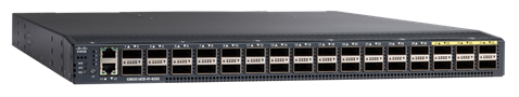
Cisco HyperFlex HX220c M5 All Flash Node
This small-footprint Cisco HyperFlex HX220c M5 All Flash Node (Figure 13) contains a 240-GB M.2 form-factor SSD that acts as the boot drive, a 240-GB housekeeping SSD drive, either a single 375-GB Optane NVMe SSD or a 1.6-TB NVMe SSD or a 400-GB SAS SSD write-log drive, and six to eight 960-GB or 3.8-TB SATA SSD drives for storage capacity. For configurations requiring self-encrypting drives (SEDs), the caching SSD is replaced with an 800-GB SAS SED SSD, and the capacity disks are replaced with 800-GB, 960-GB, or 3.8-TB SED SSDs.
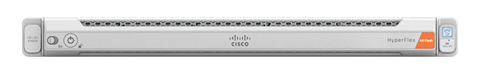
Cisco HyperFlex HX220c M5 All Flash Node
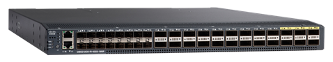
Cisco HyperFlex HX240c M5 All Flash Node
The capacity-optimized Cisco HyperFlex HX240c M5 All Flash Node (Figure 14) contains a 240-GB M.2 form-factor SSD that acts as the boot drive, a 240-GB housekeeping SSD drive, either a single 375-GB Optane NVMe SSD or a 1.6-TB NVMe SSD or a 400-GB SAS SSD write-log drive installed in a rear hot swappable slot, and 6 to 23 x 960-GB or 3.8-TB SATA SSD drives for storage capacity. For configurations requiring self-encrypting drives, the caching SSD is replaced with an 800-GB SAS SED SSD, and the capacity disks are replaced with 800-GB, 960-GB, or 3.8-TB SED SSDs.
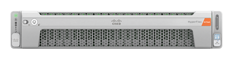
Cisco HyperFlex HX240c M5 All Flash Node
Cisco UCS Virtual Interface Card 1387 mLOM interface card
The Cisco UCS VIC 1387 (Figure 15) is a dual-port Enhanced QSFP (QSFP+) 40-Gbps Ethernet and FCoE-capable PCI Express (PCIe) modular LAN-on-motherboard (mLOM) adapter installed in the Cisco UCS C-Series Rack Servers for Cisco HyperFlex HX-Series nodes. The VIC 1387 is used in conjunction with the Cisco UCS 6332 or 6332-16UP Fabric Interconnect.
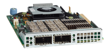
Cisco VIC 1387 mLOM card
Note: Hardware revision v03 or later of the Cisco VIC 1387 card is required for the Cisco HyperFlex HX-Series servers.
Cisco Virtual Interface Card 1457 mLOM interface card
Cisco UCS VIC 1457 (Figure 16. ) is based on the most recent generation of the Cisco UCS VIC 1400 platform. The Cisco UCS VIC 1457 is a quad-port Small Form-Factor Pluggable 28 (SFP28) mLOM card designed for the M5 generation of Cisco UCS C-Series Rack Servers. The card supports 10- and 25-Gbps Ethernet or FCoE. The card can present PCIe standards-compliant interfaces to the host, and these can be dynamically configured as either NICs or HBAs.
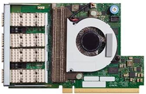
Cisco VIC 1457 mLOM card
This section details the architectural components of a Cisco HyperFlex solution with Microsoft Hyper-V to host Microsoft SQL Server databases in a virtual environment. Figure 17. shows a sample Cisco HyperFlex hyperconverged reference architecture consisting of HX-Series rack-mount servers.
Cisco HyperFlex reference architecture using Cisco HyperFlex HX240c M5 All Flash nodes
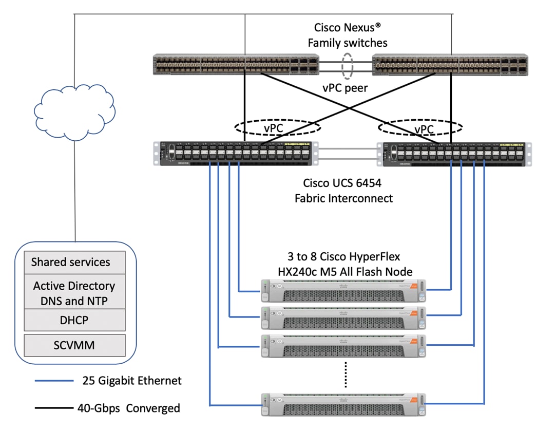
Cisco HyperFlex systems with Hyper-V are composed of a pair of Cisco UCS fabric interconnects and up to eight HX-Series rack-mount servers per cluster. Up to eight separate Cisco HyperFlex clusters can be installed under a single pair of fabric interconnects. The two fabric interconnects both connect to every HX-Series rack-mount server, and both connect to every Cisco UCS 5108 Blade Server Chassis and Cisco UCS rack-mount server. Upstream network connections, also referred as northbound network connections, are made from the fabric interconnects to the customer data center network at the time of installation. For more information about the physical connectivity of HX-Series services, computing-only servers, and fabric interconnection to the northbound network, refer the Cisco Validated Design for Cisco HyperFlex 4.0 for Virtual Server Infrastructure with Microsoft Hyper-V.
Infrastructure services such as Microsoft Active Directory, Domain Name System (DNS), Dynamic Host Configuration Protocol (DHCP), and Microsoft System Center Virtual Machine Manager (SCVMM) typically are installed outside the Cisco HyperFlex cluster. Customers can use these existing services in deploying and managing the Cisco HyperFlex and Microsoft Hyper-V cluster.
The Cisco HyperFlex storage solution uses several data protection mechanisms, as explained earlier in the section “Technology overview.” One of these mechanisms is data replication. Data replication needs to be configured during Cisco HyperFlex cluster creation. Depending on the specific performance and data protection requirements, customers can choose a replication factor of two (RF2) or three (RF3). For the solution validation, described in the section “Solution resiliency testing and validation” later in this document, the test Cisco HyperFlex cluster was configured using RF3.
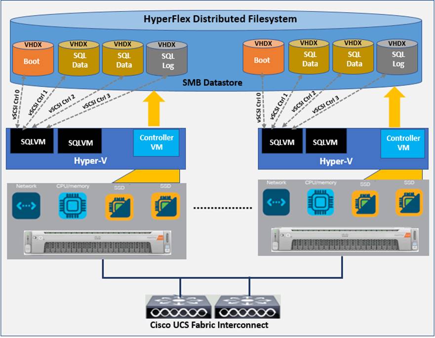
As described in the section “Technology overview,” Cisco HyperFlex distributed file system software runs in a controller virtual machine that is installed on each cluster node. These controller virtual machines pool and manage all the storage devices and expose the underlying storage as Server Message Block (SMB) shares to the Hyper-V nodes. Hyper-V exposes these SMB shares as datastores to the guest virtual machines to store their data.
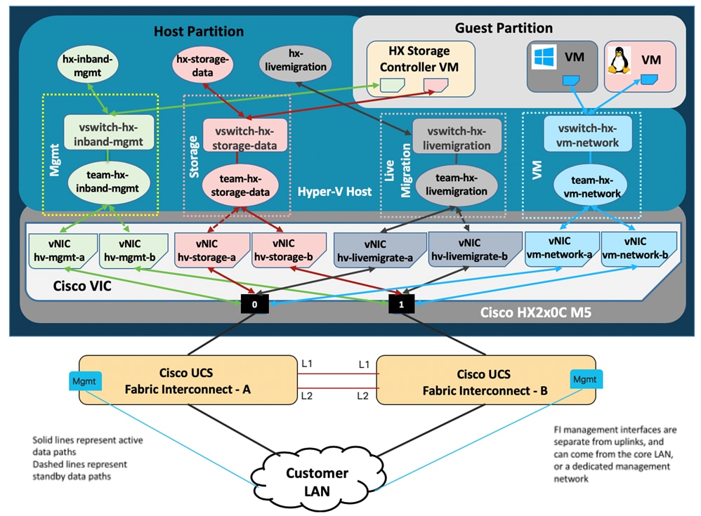
In a Cisco HyperFlex all-flash system, the Cisco VIC 1387 is used to provide the required logical network interfaces on each host in the cluster. The communication pathways in the Cisco HyperFlex system can be categorized into four traffic zones:
● Management zone: This zone consists of the connections needed to manage the physical hardware, the hypervisor hosts, and the storage controller virtual machines (SCVMs). These interfaces and IP addresses need to be available to all staff who will administer the Cisco HyperFlex system throughout the LAN and WAN. This zone must provide access to DNS and Network Time Protocol (NTP) services and allow Secure Shell (SSH) communication. This zone includes multiple physical and virtual components:
◦ Fabric interconnect management ports
◦ Cisco UCS external management interfaces used by the servers, which respond through the fabric interconnect management ports
◦ Hyper-V host management interfaces
◦ SCVM management interfaces
◦ A roaming Cisco HyperFlex cluster management interface
◦ SCVM management interfaces
● Virtual machine zone: This zone consists of the connections needed to service network I/O to the guest virtual machines that will run inside the Cisco HyperFlex hyperconverged system. This zone typically contains multiple VLANs that are trunked to the Cisco UCS fabric interconnects though the network uplinks and tagged with IEEE 802.1Q VLAN IDs. These interfaces and IP addresses need to be available to all staff and other computer endpoints that need to communicate with the guest virtual machines in the Cisco HyperFlex system throughout the LAN and WAN.
● Storage zone: This zone consists of the connections used by the HX Data Platform software, Hyper-V hosts, and the SCVMs to service the Cisco HyperFlex distributed file system. These interfaces and IP addresses need to be able to communicate with each other at all times for proper operation. During normal operation, this traffic all occurs within the Cisco UCS domain. However, in some hardware failure scenarios this traffic may need to traverse the network northbound of the Cisco UCS domain. For that reason, the VLAN used for Cisco HyperFlex storage traffic must be able to traverse the network uplinks from the Cisco UCS domain, reaching Fabric Interconnect A from Fabric Interconnect B, and the reverse. This zone includes primarily jumbo frame traffic; therefore, jumbo frames must be enabled on the Cisco UCS uplinks. This zone includes multiple components:
◦ A teamed interface used for storage traffic on each Hyper-V host in the Cisco HyperFlex cluster
◦ SCVM storage interfaces
◦ A roaming Cisco HyperFlex cluster storage interface
● Live migration zone: This zone consists of the connections used by the Hyper-V hosts to enable live migration of the guest virtual machines from host to host. During normal operation, this traffic all occurs within the Cisco UCS domain. However, in some hardware failure scenarios this traffic may need to traverse the network northbound of the Cisco UCS domain. For that reason, the VLAN used for Cisco HyperFlex live migration traffic must be able to traverse the network uplinks from the Cisco UCS domain, reaching Fabric Interconnect A from Fabric Interconnect B, and the reverse.
By using Cisco UCS virtual NIC (vNIC) templates, LAN connectivity policies, and vNIC placement policies in a service profile, eight vNICs are carved out from Cisco VIC 1387 on each HX-Series server for the four network traffic zones. Every HX-Series server will detect the network interfaces in the same order, and they will always be connected to the same VLANs through the same network fabrics. Table 1lists the vNICs and other configuration details used in the solution described in this document.
Table 1. Cisco HyperFlex vNIC template details
| vNIC template name |
hv-mgmt-a |
hv-mgmt-b |
storage-data-a |
storage-data-b |
hv-livemigrate-a |
hv-livemigrate-b |
vm-network-a |
vm-network-b |
| Setting |
Value |
Value |
Value |
Value |
Value |
Value |
Value |
Value |
| Fabric ID |
A |
B |
A |
B |
A |
B |
A |
B |
| Fabric failover |
Disabled |
Disabled |
Disabled |
Disabled |
Disabled |
Disabled |
Disabled |
Disabled |
| Target |
Adapter |
Adapter |
Adapter |
Adapter |
Adapter |
Adapter |
Adapter |
Adapter |
| Type |
Updating template |
Updating template |
Updating template |
Updating template |
Updating template |
Updating template |
Updating template |
Updating template |
| Maximum transmission unit (MTU) |
1500 |
1500 |
9000 |
9000 |
9000 |
9000 |
1500 |
1500 |
| MAC address pool |
hv-mgmt-a |
hv-mgmt-b |
storage-data-a |
storage-data-b |
hv-livemigrate-a |
hv-livemigrate-b |
vm-network-a |
vm-network-b |
| QoS policy |
Silver |
Silver |
Platinum |
Platinum |
Bronze |
Bronze |
Gold |
Gold |
| Network control policy |
HyperFlex-infra |
HyperFlex-infra |
HyperFlex-infra |
HyperFlex-infra |
HyperFlex-infra |
HyperFlex-infra |
HyperFlex-vm |
HyperFlex-vm |
| VLANs |
<<hx-inband-mgmt>> |
<<hx-inband-mgmt>> |
<<hx-storage-data>> |
<<hx-storage-data>> |
<<hx-livemigrate>> |
<<hx-livemigrate>> |
<<vm-network>> |
<<vm-network>> |
| Native VLAN |
No |
No |
No |
No |
No |
No |
No |
No |
Figure 18. shows the logical network design of an HX-Series server in a Cisco HyperFlex cluster.
Cisco HyperFlex HX-Series server logical network design
The Cisco HyperFlex system has a predefined virtual network design at the Hyper-V hypervisor level. As shown in Figure 18, four virtual switches are configured for four traffic zones. Each virtual switch is configured to use a teamed interface with two member adapters connected to both fabric interconnects. The network adapters in the team for storage, management, and live migration networks are configured in active-standby fashion. However, the network adapters in the team for the virtual machine network are configured in active-active fashion. This approach helps ensure that the data path for guest virtual machine traffic has the aggregated bandwidth needed for the specific traffic type.
Enabling jumbo frames for the storage traffic zone benefits the following SQL Server database use cases:
● Heavy write operations on SQL Server guest virtual machines caused by activities such as database restoration, rebuilding of indexes, and importation of data
● Heavy read operations on SQL Server guest virtual machines caused by typical maintenance activities such as database backup, data export operations, report queries, and rebuilding of indexes
Enabling jumbo frames for the live migration traffic zone helps the system quickly fail over SQL Server virtual machines to other hosts, thereby reducing overall database downtime.
Creating a separate logical network (using two dedicated vNICs) for guest virtual machines provides the following benefits:
● Guest traffic is isolated from other traffic, such as management and backup traffic.
● A dedicated MAC address pool can be assigned to each vNIC, simplifying the troubleshooting of connectivity problems.
As shown in Figure 18. , the virtual machine network switch is configured to use a teamed interface with two network adapters as members in active-active fashion to provide two active data paths, which results in aggregated bandwidth.
For more information about network configuration for Cisco HyperFlex HX-Series nodes using Cisco UCS network policies, templates, and service profiles, refer to the Cisco HyperFlex Network Design guidelines section of the Cisco HyperFlex 4.0 for Virtual Server Infrastructure with Microsoft Hyper-V Cisco Validated Design.
The following sections provide more details about the configuration and deployment best practices for deploying SQL Server databases on Cisco HyperFlex all-flash nodes.
Storage configuration for Microsoft SQL Server guest virtual machines
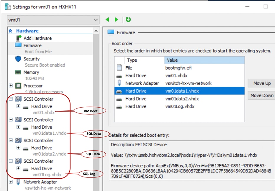
Figure 19. illustrates the storage configuration recommendations for virtual machines running SQL Server databases on Cisco HyperFlex all-flash nodes. Separate SCSI controllers are configured to host OS and SQL Server data and log volumes. For large-scale and high-performance SQL Server deployments, the recommended practice is to spread the SQL Server data files across two or more SCSI controllers for better performance, as shown in Figure 19. Additional performance guidelines are provided in the section “Deployment planning” of this document.
Storage design for Microsoft SQL Server database deployment
You must follow and implement configuration best practices and recommendations to achieve the best performance from any underlying system. This section discusses the major design and configuration best practices that you should follow when deploying SQL Server databases on all-flash Cisco HyperFlex systems with Hyper-V.
Follow the recommendations described in this section when deploying SQL Server virtual machines on all-flash Cisco HyperFlex systems with Hyper-V.
As a best practice, place all the virtual machine virtual disks for the guest OS, swap file, and SQL data and temporary database (TempDB) files and database log files on a single datastore exposed as an SMB share to the Hyper-V nodes (Figure 20). You should start deploying multiple SQL guest virtual machines using a single datastore, even though Cisco HyperFlex supports the creation of multiple datastores. The use of a single datastore simplifies management tasks and takes advantage of Cisco HyperFlex inline deduplication and compression.
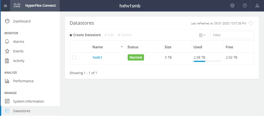
Cisco HyperFlex datastores
Microsoft SQL Server virtual machine configuration recommendations
When creating a virtual machine for deploying a SQL Server instance on an all-flash Cisco HyperFlex system with Hyper-V, follow the recommendations described here for better performance and easier administration.
Create Generation 2 virtual machines for running SQL Server (Figure 21).
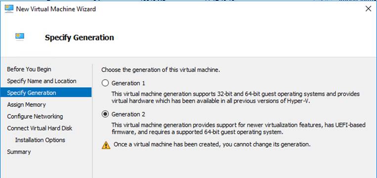
New virtual machine creation: Specify Generation
Virtual machines with multiple virtual processors have additional overhead related to synchronization in guest operating systems. You should configure multiple virtual processors only when the virtual machine requires more processing power under peak loads. Set weights and reserves on the virtual processors based on the intensity of the loads on the virtual machines. In this way, you can make sure that a large amount of the CPU is available for virtual machines and virtual processors that have high-intensity loads when there is contention for CPU resources.
The weights and reserves for virtual CPUs (vCPUs) were left at their default settings for the testing and validation described in this document (Figure 22).
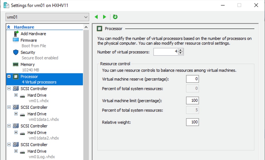
Virtual machine settings: Processor
By default, the virtual non-uniform memory address (vNUMA) topology maps to the topology of the underlying physical hardware. Default settings are recommended for better performance of NUMA-aware applications such as SQL Server (Figure 23). However, in a few scenarios (for example, to implement licensing constraints or to help ensure that the vNUMA is aligned with the physical NUMA) you may want to change the vNUMA settings. In general, however, you should not change these settings unless the changes are thoroughly tested in the given environment.
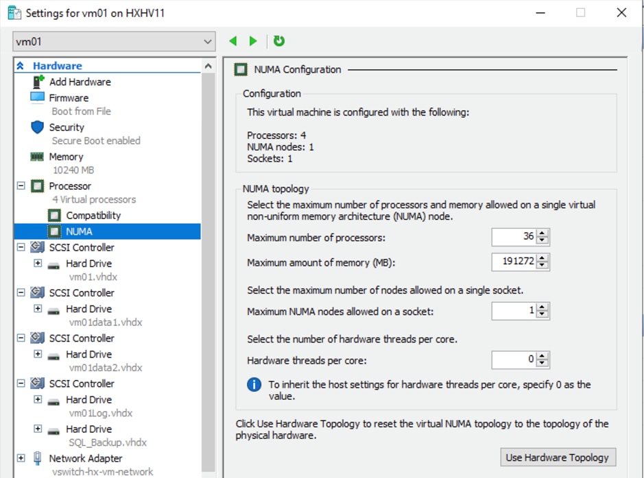
Virtual machine settings: NUMA Configuration
Memory settings
SQL Server database transactions are usually CPU and memory intensive. In a processing-heavy online transaction processing (OLTP) database system, the recommended approach is to assign static memory to the SQL Server virtual machines (Figure 24). This approach helps ensure that the memory assigned to the SQL Server virtual machine is committed and eliminates the possibility of that the memory will balloon and be paged out by the hypervisor.
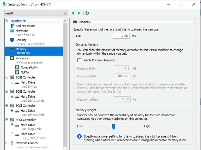
Virtual machine settings: Memory
To provide greater stability to a virtual machine workload, grant Lock Pages in Memory user rights to the SQL Server service account (Figure 25). This setting is helpful when Hyper-V dynamic memory tries to reduce the virtual machine’s memory. In such cases, Hyper-V prevents Microsoft Windows from paging out a large amount of buffer pool memory from the process, thereby providing a positive impact on performance.
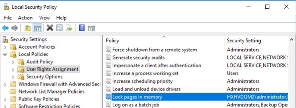
Lock Pages in Memory user rights
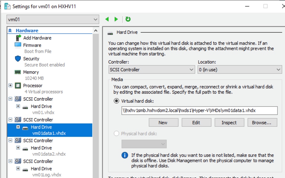
SCSI controller recommendations
For large-scale and high I/O databases, you always should use multiple virtual disks, and you should distribute those virtual disks across multiple SCSI controller adapters instead of assigning them all to a single SCSI controller (Figure 26). This approach helps ensure that the guest virtual machine accesses multiple virtual SCSI controllers (four SCSI controllers maximum per guest virtual machine) and hence enables greater concurrency, using the multiple queues available for the SCSI controllers.
Virtual machine settings: SCSI controllers and hard drives
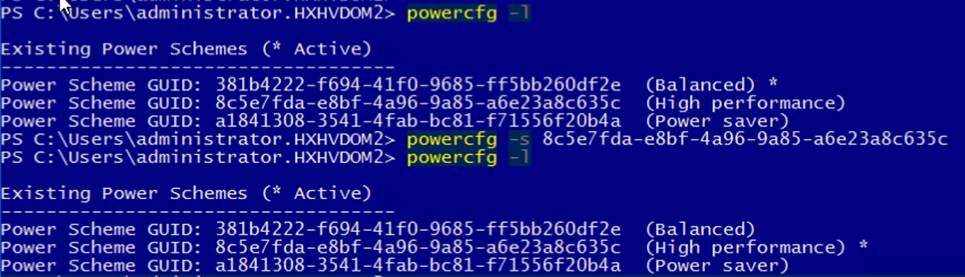
HX-Series servers are optimally configured with appropriate BIOS policy settings at the host level and do not require any changes. Similarly, Hyper-V host power management options are set for high performance at the time of HX-Series node installation by the installer (Figure 27).
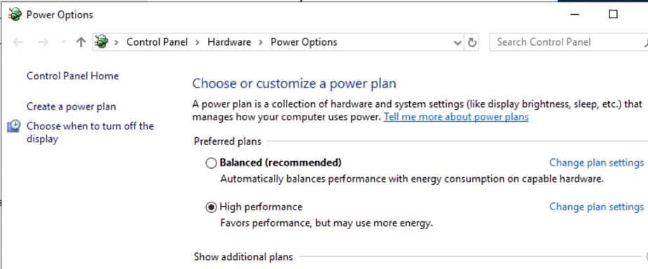
Power setting on Cisco HyperFlex HX-Series hypervisor node
In the SQL Server guest virtual machine, you should set the power management option to High Performance for optimal database performance (Figure 28. ).
Microsoft SQL Server guest virtual machine power settings in Microsoft Windows OS
For more information about configuration recommendations specific to SQL Server in virtualized environments, see http://download.microsoft.com/download/6/1/d/61dde9b6-ab46-48ca-8380-d7714c9cb1ab/best_practices_for_virtualizing_and_managing_sql_server_2012.pdf.
Achieving database high availability
Cisco HyperFlex storage systems incorporate efficient storage-level availability techniques such as data mirroring (RF2 and RF3) and native snapshots to help ensure continuous data access to the guest virtual machines hosted on the cluster.
This section discusses the high-availability techniques that help enhance the availability of virtualized SQL Server databases (in addition to the storage-level availability that comes with Cisco HyperFlex solutions).
The availability of the individual SQL Server database instance and virtual machines can be enhanced using the following technologies:
● SQL Server Failover Cluster Instance: Adds a virtual machine cluster role for high availability
● SQL Server Always On: Uses availability groups to achieve database-level high availability
Single virtual machine and SQL Server instance-level high availability using Failover Cluster Manager roles
The Cisco HyperFlex solution uses Hyper-V clustering to provide high availability to the hosted virtual machines. Because the exposed SMB share is accessible on all the hosts in the cluster, they act as a shared storage environment to help the virtual machines migrate between the hosts. This configuration helps the virtual machines migrate seamlessly in the event of either a planned or unplanned outage.
For more information, see https://docs.microsoft.com/en-us/powershell/module/failoverclusters/add-clustervirtualmachinerole?view=win10-ps.
Database-level high availability using SQL Always On availability group feature
The database-level availability of a single or multiple databases can be provided using the SQL Server Always On feature that is part of Microsoft SQL Server Enterprise Edition. Introduced in SQL Server 2012, Always On availability groups increase the availability of a set of user databases for an enterprise. An availability group supports a failover environment for a discrete set of user databases, known as availability databases, that fail over together. An availability group supports a set of read-write primary databases and one to eight sets of corresponding secondary databases. Optionally, secondary databases can be made available for read-only access and some backup operations. For more information about this feature, see https://msdn.microsoft.com/en-us/library/hh510230.aspx.
SQL Server Always On availability groups take advantage of the Microsoft Windows Server Failover Cluster (WSFC) platform technology. WSFC uses a quorum-based approach to monitor the overall cluster health and enhance node-level fault tolerance. Always On availability groups will be configured as WSFC resources, and their availability will depend on the underlying WSFC quorum modes and voting configuration, as explained in https://docs.microsoft.com/en-us/sql/sql-server/failover-clusters/windows/wsfc-quorum-modes-and-voting-configuration-sql-server.
Using Always On availability groups with synchronous replication that supports automatic failover capabilities, enterprises can achieve seamless database availability across the database replicas configured. Figure 29 shows a scenario in which an Always On availability group is configured between the SQL Server instances running on two separate Cisco HyperFlex storage systems. To help ensure that the involved databases can be protected with guaranteed high performance and no data loss in the event of a failure, proper planning needs to be done to maintain a low-latency replication network link between the clusters.
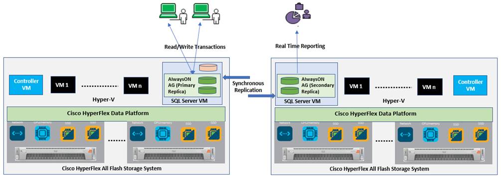
Synchronous Always On configuration across Cisco HyperFlex all-flash systems
Follow the guidelines listed here to place the primary replica in an all-flash high-performance cluster. There are no specific rules about the infrastructure used for hosting a secondary replica.
● With synchronous replication (no data loss)
◦ The replicas need to be hosted on similar hardware configurations to help ensure that database performance is not compromised while waiting for an acknowledgment from the replicas.
◦ A high-speed low latency network connection between the replicas needs to be ensured.
● With asynchronous replication (minimal data loss)
◦ The performance of the primary replica does not depend on the secondary replica, so it can be hosted on low-cost hardware solutions as well.
◦ The amount to data loss will depend on the network characteristics and the performance of the replicas.
A Microsoft article describes considerations for deploying Always On availability groups, including prerequisites and restrictions and recommendations for host computers, use of WSFC, server instances, and availability groups. See Availability Group: Prerequisites, Restrictions, and Recommendations - SQL Server Always On | Microsoft Learn
Deploying Microsoft SQL Server
This section describes how to deploy test SQL Server virtual machine on a Cisco HyperFlex all-flash system.
Cisco HyperFlex 4.0 installation and deployment on Microsoft Hyper-V
This document focuses on Microsoft SQL Server virtual machine deployment and assumes the availability of an already running healthy all-flash Cisco HyperFlex 4.0 cluster on Hyper-V.
Step-by-step instructions for deploying and configuring the Cisco HyperFlex system on Hyper-V are outside the scope of this document. For more information about deploying a Cisco HyperFlex 4.0 all-flash system on Hyper-V, refer to the installation guide at https://www.cisco.com/c/en/us/td/docs/unified_computing/ucs/UCS_CVDs/hx40_vsi_microsoft_hyperv.html.
This section provides step-by-step procedures for deploying Microsoft SQL Server 2019 on a Microsoft Windows Server 2019 virtual machine on a Cisco HyperFlex all-flash system with NVMe cache storage. Cisco recommends following the guidelines at http://download.microsoft.com/download/6/1/d/61dde9b6-ab46-48ca-8380-d7714c9cb1ab/best_practices_for_virtualizing_and_managing_sql_server_2012.pdf to create an optimally performing SQL Server database configuration.
Before proceeding to create a guest virtual machine and install SQL Server on the guest, you need to gather certain required information. This document assumes that you have information such as the IP addresses; server names; and DNS, NTP, VLAN details of the Cisco HyperFlex system available before proceeding with SQL Server virtual machine deployment on the Cisco HyperFlex all-flash system. Table 2provides an example of a database checklist.
Table 2. Virtual interface order within Cisco HyperFlex HX-Series server
| Component |
Details |
| Cisco UCS Manager user name and password |
User name admin and <<password>> |
| Cisco HyperFlex cluster credentials |
User name admin and <<password>> |
| Cisco HyperFlex admin service account in Active Directory |
Domain name\hxadmin / <<password>> |
| Datastore names and sizes to be used for SQL Server virtual machine deployments |
HXDS1: 5 TB |
| Microsoft Windows and SQL Server ISO file location |
\HXDS1\ISOs\ |
| Virtual machine configuration: vCPUs, memory, and virtual machine disk (VMDK) files and sizes |
● vCPUs: 4
● Memory: 10 GB
● OS: 75 GB
● Data volumes: SQL-DATA1 (350 GB) and SQL-DATA2 (350 GB)
● Log volume: SQL-Log (250 GB)
All of these files are to be stored in the HXDS1 datastore. |
| Microsoft Windows and SQL Server license keys |
<<Client provided>> |
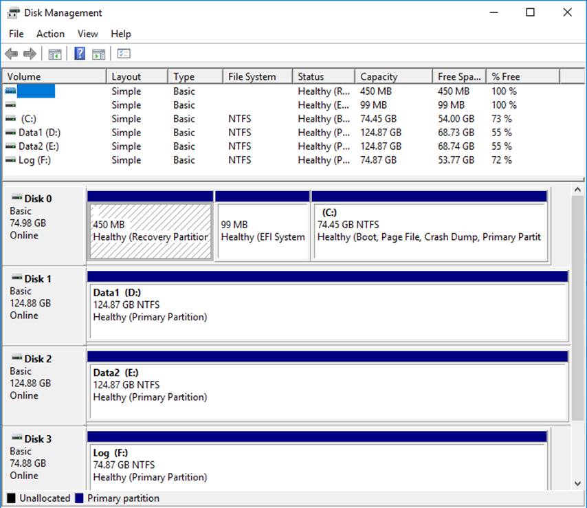
| Drive letters for OS and SQL swap, data, and log files |
● OS: C:\
● SQL-Data1: D:\
● SQL-Data2: E:\
● SQL-Log: F:\
|
Follow these steps to deploy SQL Server on the Cisco HyperFlex system:
1. Verify that the Cisco HyperFlex cluster is healthy and configured correctly. Log in to the Cisco HyperFlex Connect dashboard using the Cisco HyperFlex cluster IP address (Figure 30).
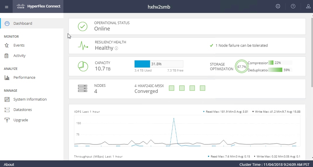
Cisco HyperFlex cluster health status
2. Make sure that Windows Hyper-V host service profiles in Cisco UCS Manager are all healthy without any errors. Figure 31 shows the service profile status summary in the Cisco UCS Manager GUI.
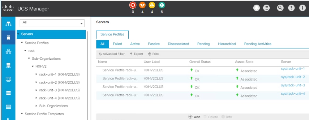
Cisco UCS Manager service profiles
3. Create datastores for deploying SQL Server guest virtual machines and make sure that the datastores are mounted on all the Cisco HyperFlex cluster nodes. The procedure for adding datastores to the Cisco HyperFlex system is provided in the Cisco HyperFlex Administration Guide. Figure 32 shows the creation of a sample datastore. This example uses an 8-KB block size for the datastore, which is appropriate for the SQL Server database.
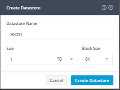
Cisco HyperFlex datastore creation
4. Install the Windows Server 2019 virtual machine using the instructions in the Microsoft article here. As described previously in the “Deployment procedure” section of this document, make sure that the OS and data and log files are segregated and balanced by configuring separate virtual SCSI controllers. In Hyper-V Manager, select and right-click the virtual machine and click Settings to change the virtual machine configuration, as shown in Figure 33.
Note: Fixed-size Hyper-V Virtual Hard Disk (VHDX) uses the full amount of space specified during Virtual Hard Disk (VHD) creation, and it can deliver better throughput than dynamic VHDX.
Microsoft SQL Server virtual machine configuration
5. Initialize, format, and label the volumes for Windows OS files and SQL Server data and log files. Use 64 KB as the allocation unit size when formatting the volumes. Figure 34 (the Windows OS disk management utility) shows a sample logical volume layout of the test virtual machine.
Microsoft SQL Server virtual machine disk layout
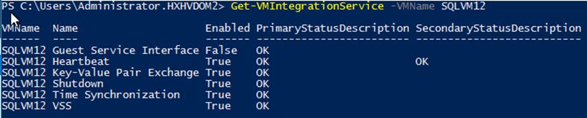
6. When the Windows guest OS is installed in the virtual machine, as a best practice you should have the latest Virtual Machine Integration Service enabled and running, as shown in Figure 35. For more information about managing Hyper-V integration services, click here.
Virtual Machine Integration Service
7. Install SQL Server 2019 on the Windows Server 2019 virtual machine. Follow the Microsoft documentation to install the database engine on the guest virtual machine.
8. Download and mount the required edition of the SQL Server 2019 ISO file on the virtual machine from Hyper-V Manager. Choose the Standard or Enterprise Edition of SQL Server 2019 based on your application requirements .
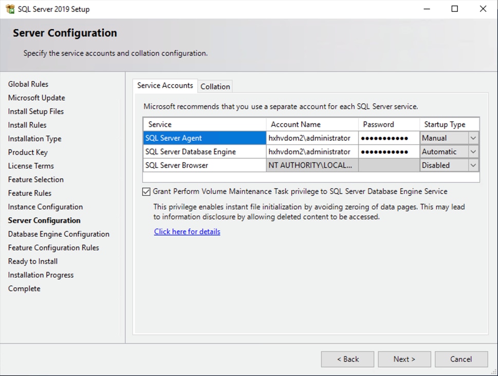
9. In the Server Configuration window of the SQL Server installation process, make sure that instant file initialization is enabled by enabling the check box as shown in Figure 36. . This setting helps ensure that the SQL Server data files are instantly initialized by avoiding zeroing operations.
Enabling instant file initialization during Microsoft SQL Server deployment
10. If the domain account used as the SQL Server service account is not a member of the local administrator group, add the SQL Server service account to the “Perform volume maintenance tasks” policy using the Local Security Policy editor as shown in Figure 37.
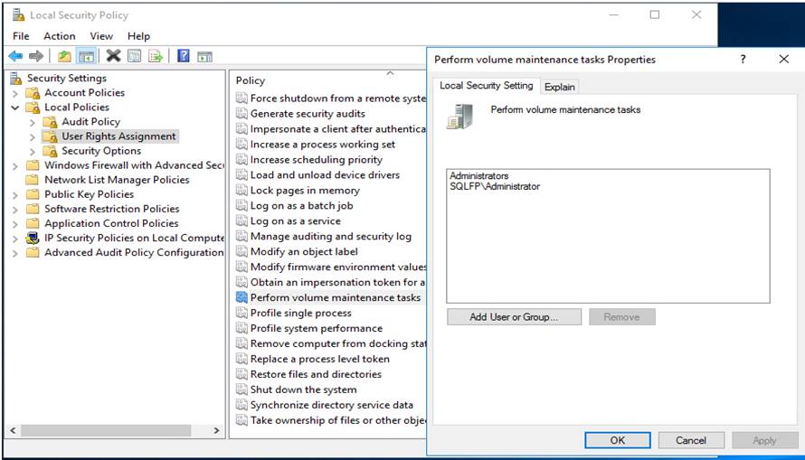
Granting volume maintenance task permissions to the Microsoft SQL Server service account
11. In the Database Engine Configuration window, under the TempDB tab, make sure that the number of TempDB data files is equal to 8 when the number of vCPUs or logical processors of the SQL Server virtual machine is less than or equal to 8. If the number of logical processors is more than 8, start with 8 data files and add data files in multiples of 4 when contention occurs on the TempDB resources. Figure 38 shows 8 TempDB files specified for a SQL Server virtual machine that has 8 vCPUs. Also, as a general best practice, keep the TempDB data and log files on two different volumes.
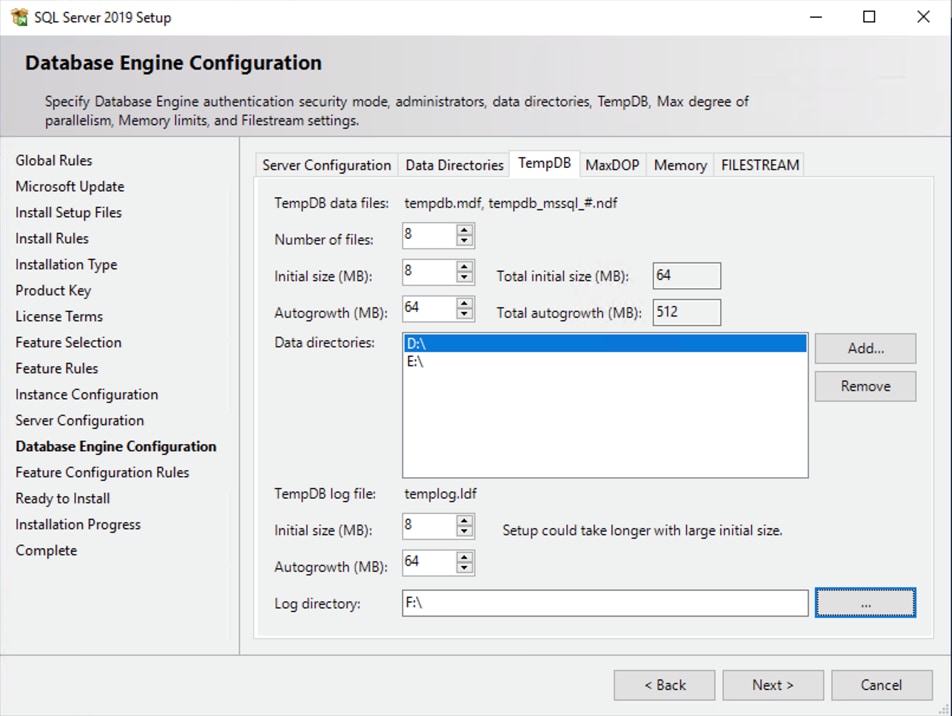
TempDB data and log files location
12. When SQL Server is successfully installed, use SQL Server Configuration Manager to verify that the SQL Server service is up and running (Figure 39).
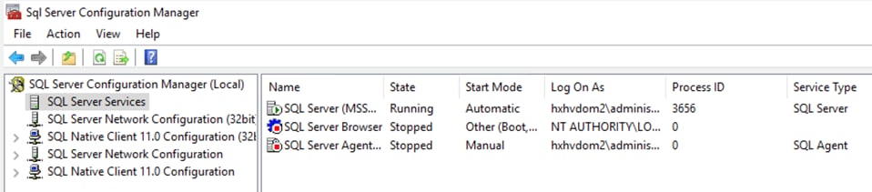
Microsoft SQL Server Configuration Manager
13. Create a user database using Microsoft SQL Server Management Studio or Transact-SQL so that the database logical file layout is in line with the desired volume layout. Detailed instructions are provided here.
Solution resiliency testing and validation
This section discusses some of the tests conducted to validate the robustness of the SQL Server and Cisco HyperFlex all-flash solution and the configuration used for the validation. These tests were conducted on a Cisco HyperFlex cluster built with four Cisco HyperFlex HX240c M4 All-Flash Nodes. Table 3lists the component details of the test setup. Other failure scenarios (failures of disk, network, etc.) are outside the scope of this document.
| Component |
Details |
| Cisco HyperFlex HX Data Platform |
● Cisco HyperFlex HX Data Platform Software Release 4.0(2a)
● Replication factor: 3
● Inline data deduplication and compression: Enabled (default)
|
| Fabric interconnects |
● 2 fourth-generation Cisco UCS 6454 Fabric Interconnects
● Cisco UCS Manager Firmware Release 4.0 (4d)
|
| Servers |
4 Cisco UCS HyperFlex HX240c M5 All Flash Nodes |
| Processors per node |
2 Intel Xeon Gold 6240 CPUs at 2.6 GHz with 18 cores each |
| Memory per node |
384 GB (12 x 32 GB) at 2933 MHz |
| Cache drives per node |
1 x 2.5-inch U.2 375-GB Intel XPoint P4800 NVMe medium performance |
| Capacity drives per node |
10 x 960-GB 2.5-inch Enterprise Value 6-GB SATA SSD |
| OS and hypervisor |
Microsoft Windows Server 2019 Hyper-V (v1809 Build 17763.107) |
| Network switches (optional) |
2 Cisco Nexus 9396PX Switches |
| Guest operating system |
Microsoft Windows 2019 Datacenter Edition |
| Database |
Microsoft SQL Server 2019 |
| Database workload |
OLTP with 70:30 read-write mix |
The following major tests were conducted on the setup:
● Node failure tests
● Fabric interconnect failure tests
● Database maintenance tests
All these tests used the HammerDB testing tool to generate the required stress on the guest SQL Server virtual machine. A separate client machine located outside the Cisco HyperFlex cluster was used to run the testing tool and generate the database workload.
This section contains examples of ways in which SQL Server workloads can take advantage of the Cisco HyperFlex HX Data Platform architecture and its performance scaling attributes.
Performance with single large virtual machine
The Cisco HyperFlex HX Data Platform uses a distributed architecture. A main advantage of this approach is that the cluster resources form a single, seamless pool of storage capacity and performance resources. This approach allows any individual virtual machine to take advantage of the overall cluster resources; the virtual machine is not limited to the resources on the local node that hosts it. This unique capability is a significant architectural differentiator that the HX Data Platform provides.
Several common data center deployment scenarios in particular benefit from the HX Data Platform:
● Virtual machine hotspot: Rarely do all the virtual machines in a shared virtual infrastructure uniformly utilize the resources. Capacity increases for individual virtual machines usually differ, and their performance requirements are different at different points in time. With the Cisco HyperFlex distributed architecture, the infrastructure easily absorbs these hotspots, without causing capacity or performance hotspots in the infrastructure.
● Large virtual machine: Because the cluster presents a common pool of resources, organizations can deploy large applications and virtual machines with performance and capacity requirements that exceed the capability of any single node in the cluster.
A performance test was conducted with a large SQL Server virtual machine. The cluster setup was the same as that listed in Table 3. Table 4 provides the details of the virtual machine configuration and workload used in this test. An OLTP workload with a 70:30 read-write ratio was exerted on the guest virtual machine. The workload stressed the virtual machine with CPU utilization of up to 70 percent, which resulted in Hyper-V host CPU utilization of greater than 10 percent.
Table 4. Virtual machine and workload details for test using single large virtual machine
| Configuration |
Details |
| Virtual machine |
● 8 vCPUs with 12 GB of memory (8 GB assigned to SQL Server)
● 2 data volumes and one log volume (each with a dedicated SCSI controller)
|
| Workload |
● Toolkit: HammerDB
● Users: 60
● Data warehouses: 8000
● Database size: 800 GB
● Read-write ratio: About 70:30
|
Figure 40 shows the performance for the single virtual machine running a large SQL Server workload for about 8 hours. The following points are noteworthy:
● A large virtual machine with a very large working data set size can achieve a sustained high I/O operations per second (IOPS) rate using resources (capacity and performance) from all four nodes in the cluster. Note that the IOPS rate can be scaled even higher with an even larger virtual machine.
● Deduplication and compression are enabled by default, and this was the configuration used during this test.
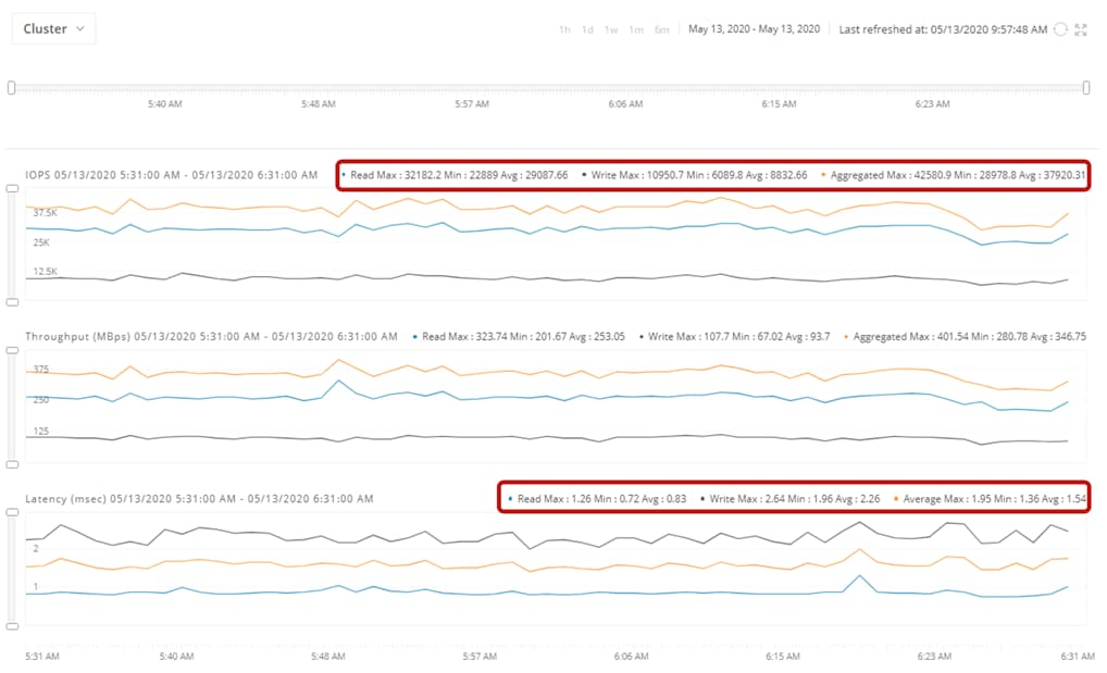
Single large working SQL Server database workload on Cisco HyperFlex all-flash cluster
This test demonstrates the capability of Cisco HyperFlex systems to use the resources from all nodes in the cluster to meet the performance (and capacity) needs of any given virtual machine.
Performance scaling with multiple virtual machines
The seamless pool of capacity and performance resources presented by the Cisco HyperFlex cluster can also be accessed by multiple smaller virtual machines. In the test reported here, multiple virtual machines are each running a SQL Server instance with HammerDB. The cluster setup used is the same as that listed in Table 3. Table 5 provides the details of the virtual machine configuration and the workload used in this test. An OLTP workload with a 70:30 read-write ratio was exerted on each guest virtual machine. The workload stressed each virtual machine with guest CPU utilization of up to 25 percent.
Table 5. Virtual machine and workload details for test using multiple smaller virtual machines
| Configuration |
Details |
| Virtual machines |
● 4 vCPUs with 10 GB of memory (8 GB is assigned to SQL Server)
● 2 data logical unit numbers (LUNs) and 1 log LUN
● Virtual machine count scales in units of 4 (1 virtual machine per node).
|
| Workload |
● Toolkit: HammerDB
● Users: 5
● Data warehouses: 1000
● Database size: About 100 GB
● Read-write ratio: About 70:30
|
Figure 41 shows the performance scaling achieved by increasing the number of virtual machines in the cluster from 4 (1 virtual machine per node), to 8 (2 virtual machines per node), and finally to 12 (3 virtual machines per node). The performance data shown in the graphs was captured using the Microsoft Windows Performance Monitor (Perfmon) tool. Note that the numbers show the sustained level of performance. Also, deduplication and compression are on by default, and this was the configuration used during this test. If one or more virtual machines need additional IOPS or throughout, the virtual machines will be able to get the increase in storage performance provided that the virtual machine itself is not experiencing a CPU or memory bottleneck and that additional performance headroom is available in the cluster. A 4-node Cisco HyperFlex all-flash system with NVMe cache storage can achieve nearly 50,000 IOPS with write latency of less than 4 milliseconds (ms).
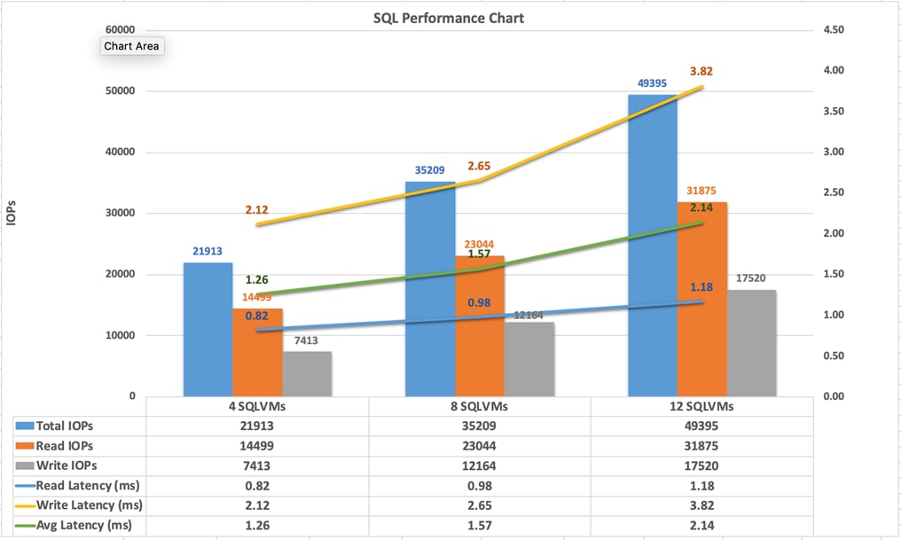
Performance scaling with virtual machine count in the cluster with 4, 8, and 12 virtual machines
This test demonstrates the capability of the HX Data Platform to scale cluster performance by using a large number of virtual machines.
Common database maintenance scenarios
This section discusses common database maintenance activities and provides some guidelines for planning database maintenance activities on the SQL Server virtual machines deployed on the all-flash Cisco HyperFlex system.
Among the most common database maintenance activities are export, import, index rebuild, backup, and restore operations and running database consistency checks at regular intervals. The I/O pattern of these activities usually differs from that of business operational workloads hosted on the other virtual machines in the same cluster. These maintenance activities typically generate sequential I/O operations, whereas business transactions typically generate random I/O operations (in the case of transactional workloads). When a sequential I/O pattern is introduced into the system alongside a random I/O pattern, I/O-sensitive database applications may be negatively affected. Hence, care must be used in sizing the environment and to control the impact of database maintenance activities that are run during business hours in production environments.
The following list provides some guidelines for running maintenance activities to avoid a negative impact on business operations:
● As a general best practice, all maintenance activities such as export, import, backup, and restore operations and database consistency checks should be scheduled to run outside business hours, when no critical business transactions are running on the underlying Cisco HyperFlex system, to avoid affecting ongoing business operations. Another way to limit the impact of maintenance activities is to size the system with appropriate headroom.
● In the case of an urgent need to run maintenance activities during business hours, administrators should know the I/O limits of their hyperconverged systems and plan to run the activities accordingly.
● For clusters running at peak load or near saturation, when exporting a large volume of data from the SQL Server database hosted on any hyperconverged system to any flat files, locate the destination files outside the Cisco HyperFlex cluster. This approach will prevent the export operation from negatively affecting the other guest virtual machines running in the same cluster. For small data exports, the destination files can be in the same cluster.
● Most import data operations are followed by re-creation of indexes and statistics to update the database metadata pages. Usually index re-creation causes a lot of sequential read and write operations; hence, you should schedule data import operations for outside business hours.
● Database restore, backup, and index rebuild activities and database consistency checks typically generate a huge number of sequential I/O operations. Therefore, these activities should be scheduled to run outside business hours.
In the case of complete guest system or database backups, you should not keep the backups in the same cluster, because doing so would not provide protection if the entire cluster is lost: for example, during a geographic failure or large-scale power outage. Data protection for virtualized applications that are deployed on hyperconverged systems is becoming a major challenge for organizations, and a flexible, efficient, and scalable data protection platform is needed.
Cisco HyperFlex systems integrate with several backup solutions. For example, the Cisco HyperFlex solution together with Veeam Availability Suite provides a flexible, agile, and scalable infrastructure that is protected and easy to deploy.
Performance demands for workloads are rarely static. They tend to increase or decrease over time. A main advantage of the Cisco HyperFlex architecture is the seamless scalability of the cluster. In scenarios in which the existing workload needs grow, Cisco HyperFlex can handle the change by increasing the existing cluster’s computing, storage capacity, and storage performance capabilities, depending on the resource requirements. This capability gives administrators enough flexibility to right-size their environments based on today’s needs without having to worry at the same time about future growth.
Troubleshooting performance problems
For information about how to use Windows Perfmon to identify problems in host and virtual machines that do not perform as expected, see https://docs.microsoft.com/en-us/windows-server/administration/performance-tuning/role/hyper-v-server/detecting-virtualized-environment-bottlenecks.
For information about best practices for virtualizing and managing SQL Server, see http://download.microsoft.com/download/6/1/d/61dde9b6-ab46-48ca-8380-d7714c9cb1ab/best_practices_for_virtualizing_and_managing_sql_server_2012.pdf.
Some performance problems that commonly occur on virtualized and hyperconverged systems are described here.
High Microsoft SQL Server guest CPU utilization
When high CPU utilization and lower disk latency occurs on SQL Server guest virtual machines and CPU utilization on Hyper-V hosts appears to be normal, the virtual machine may be experiencing CPU contention. In that case, the solution may be to add more vCPUs to the virtual machine because the workload is demanding more CPU resources.
When high CPU utilization is observed on both the guest and the host virtual machines, one option is to upgrade to a higher-performing processor.
High disk latency on Microsoft SQL Server guest virtual machine
When higher disk latency is observed on SQL Server guest virtual machines, you have several options for troubleshooting.
Use Windows Perfmon to identify latencies and follow the options discussed in the section “Deployment planning” earlier in this document.
If the Cisco HyperFlex system storage capacity is nearing the expected threshold (exceeding 60 percent utilization), both the guest and the host SQL Server virtual machines may experience I/O latency. In this scenario, you should scale up the cluster by adding new HX-Series nodes to the cluster.
The Cisco HyperFlex HX Data Platform revolutionizes data storage for hyperconverged infrastructure deployments that support new IT consumption models. The platform’s architecture and software-defined storage approach gives you a purpose-built, high-performance distributed file system with a wide array of enterprise-class data management services. With innovations that redefine distributed storage technology, the data platform provides you an optimal hyperconverged infrastructure for delivering adaptive IT infrastructure. Cisco HyperFlex systems lower both operating expenses (OpEx) and capital expenditures (CapEx) by allowing you to scale as you grow. They also simplify the convergence of computing, storage, and network resources.
All-flash memory configurations enhance the unique architectural capabilities of https://www.cisco.com/site/us/en/products/computing/hyperconverged-infrastructure/index.html
to meet the high-performance, low-latency requirements of enterprise applications. The architecture allows hosted virtual machines to use all the resources in a cluster efficiently, regardless of the host. This design also makes virtualized SQL Server an excellent candidate for deployment on high-performing Cisco HyperFlex all-flash systems.
Lab resiliency tests presented in this document show the robustness of a Cisco HyperFlex solution for hosting I/O-sensitive applications such as Microsoft SQL Server. The system performance tuning guidelines in this document address platform-specific tunings that will help organizations attain optimal performance for a SQL Server virtual machine on Cisco HyperFlex all-flash systems. The SQL Server performance observed on Cisco HyperFlex systems and described in this document demonstrates that the Cisco HyperFlex all-flash system is an excellent platform for hosting high-performing, low-latency applications such as Microsoft SQL Server databases.
https://www.cisco.com/c/en_in/products/hyperconverged-infrastructure/index.html
https://docs.microsoft.com/en-us/windows-server/virtualization/hyper-v/hyper-v-on-windows-server
https://www.microsoft.com/en-us/sql-server/sql-server-2019