Einleitung
In diesem Dokument wird die Verwendung von BGP Community Values zur Steuerung der Routing-Richtlinie in Upstream-Anbieternetzwerken beschrieben.
Voraussetzungen
Anforderungen
In diesem Dokument werden Kenntnisse über das Border Gateway Protocol (BGP)-Routing-Protokoll und dessen Funktionsweise benötigt.
Verwendete Komponenten
Dieses Dokument ist nicht auf bestimmte Software- und Hardware-Versionen beschränkt. Die Informationen in diesem Dokument basieren jedoch auf der folgenden Softwareversion:
Die Informationen in diesem Dokument beziehen sich auf Geräte in einer speziell eingerichteten Testumgebung. Alle Geräte, die in diesem Dokument benutzt wurden, begannen mit einer gelöschten (Nichterfüllungs) Konfiguration. Wenn Ihr Netzwerk in Betrieb ist, stellen Sie sicher, dass Sie die möglichen Auswirkungen aller Befehle kennen.
Hintergrundinformationen
Auch wenn die Communitys selbst den Prozess für den BGP-besten Pfad nicht verändern, können sie als Markierungen für bestimmte Routen verwendet werden. Upstream-Service-Provider-Router können diese Flags verwenden, um innerhalb ihres Netzwerks bestimmte Routing-Richtlinien (z. B. die lokale Präferenz) anzuwenden.
Provider ordnen Ihre konfigurierbaren Community-Werte den entsprechenden lokalen Voreinstellungen innerhalb des Anbieternetzwerks zu. Sie können spezifische Richtlinien festlegen, für die LOCAL_PREF im Anbieternetzwerksatz und die entsprechenden Community-Werte in den Routing-Updates geändert werden müssen.
Eine Community ist eine Gruppe von Präfixen, die gemeinsame Eigenschaften haben und mit dem BGP-Community-Attribut konfiguriert werden können. Das BGP-Community-Attribut ist ein optionales transitives Attribut variabler Länge. Das Attribut besteht aus einem Satz von vier Oktetten, die eine Community angeben. Die Community-Attributwerte werden mit einer AS-Nummer (Autonomous System) in den ersten beiden Oktetten codiert, während die beiden anderen Oktetten vom AS definiert werden. Ein Präfix kann mehr als ein Community-Attribut aufweisen. Ein BGP-Sprecher, der mehrere Community-Attribute in einem Präfix erkennt, kann auf der Grundlage eines, einiger oder aller Attribute agieren. Ein Router hat die Möglichkeit, ein Community-Attribut hinzuzufügen oder zu ändern, bevor der Router das Attribut an andere Peers weitergibt. Weitere Informationen zum Community-Attribut finden Sie in den BGP-Anwenderberichten.
Das Attribut "local preference" gibt dem AS an, welcher Pfad bevorzugt wird, um ein bestimmtes Netzwerk zu erreichen. Wenn mehrere Pfade zum gleichen Ziel vorhanden sind, wird der Pfad mit der höheren Einstellung ausgewählt (der Standardwert des lokalen Einstellungsattributs ist 100). Weitere Informationen finden Sie unter Fallstudien.
Konventionen
Weitere Informationen zu Dokumentkonventionen finden Sie unter Cisco Technical Tips Conventions (Technische Tipps von Cisco zu Konventionen).
Konfigurieren und Steuern der Routing-Richtlinie
Anmerkung: Weitere Informationen zu den in diesem Dokument verwendeten Befehlen finden Sie mit dem Tool Befehlssuche.
Zur Vereinfachung wird davon ausgegangen, dass die Zuordnung von Community-Attributen und lokalen Voreinstellungsattributen zwischen dem Upstream-Service-Provider (AS 100) und Ihrem Gerät (AS 30) eingerichtet wird.
|
Lokale Präferenz
|
Gemeinschaftswerte
|
|
130
|
100:300
|
|
125
|
100:250
|
Wenn die Präfixe mit einem Community-Attribut von 100:300 angekündigt werden, setzt der Upstream-Service Provider die lokale Präferenz für diese Routen auf 130 und 125, wenn das Community-Attribut 100:250 entspricht.
Dadurch haben Sie die Kontrolle über die Routing-Richtlinie im Service-Provider-Netzwerk, wenn Sie die Community-Werte der dem Service Provider angekündigten Präfixe ändern.
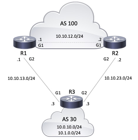
Im Netzwerkdiagramm möchte AS 30 diese Routing-Richtlinie mit den Community-Attributen verwenden.
-
Der von AS 100 an das Netzwerk 10.0.10.0/24 eingehende Datenverkehr wird über die R1-R3-Verbindung geleitet. Wenn die R1-R3-Verbindung ausfällt, wird der gesamte Datenverkehr über R2-R3 geleitet.
-
Der von AS 100 an das Netzwerk 10.1.0.0/24 eingehende Datenverkehr wird über die R2-R3-Verbindung geleitet. Wenn die R2-R3-Verbindung ausfällt, wird der gesamte Datenverkehr über R1-R3 geleitet.
Um diese Routing-Richtlinie zu erreichen, kündigt R3 seine Präfixe wie folgt an:
Zu R1:
- 10.0.10.0/24 mit Community-Attribut 100:300
- 10.1.0.0/24 mit Community-Attribut 100:250
Zu R2:
Wenn die BGP-Nachbarn R1 und R2 die Präfixe von R3 empfangen haben, wenden R1 und R2 die konfigurierte Richtlinie basierend auf der Zuordnung zwischen den Attributen für die Community und die lokalen Einstellungen an (siehe vorige Tabelle), um die von Ihnen (AS 30) diktierte Routing-Richtlinie zu erreichen. R1 installiert die Präfixe in der BGP-Tabelle.
R2 installiert das Präfix in seiner BGP-Tabelle:
Da bei den BGP-Pfadauswahlkriterien eine höhere lokale Präferenz bevorzugt wird, wird der Pfad mit einer lokalen Präferenz von 130 (130 ist größer als 125) als bester Pfad innerhalb von AS 100 ausgewählt und in der IP-Routing-Tabelle von R1 und R2 installiert. Weitere Informationen zu BGP-Pfadauswahlkriterien finden Sie unter BGP Bester Pfadauswahlalgorithmus.
Netzwerkdiagramm
Konfigurationen
In diesem Dokument werden folgende Konfigurationen verwendet:
| R3-Konfiguration |
hostname R3
!
interface Loopback0
 ip address 10.0.10.1 255.255.255.0
!
interface Loopback1
 ip address 10.1.0.1 255.255.255.0
!
interface GigabitEthernet1
 ip address 10.10.13.3 255.255.255.0

!--- Interface connected to R1
!
interface GigabitEthernet2
 ip address 10.10.23.3 255.255.255.0

!--- Interface connected to R2
!
router bgp 30
 bgp router-id interface Loopback0
 network 10.0.10.0 mask 255.255.255.0
 network 10.1.0.0 mask 255.255.255.0

!--- Network commands announce prefix 10.0.10.0/24 and 10.1.0.0/24.

 neighbor 10.10.13.1 remote-as 100

!--- Establishes peering with R1

 neighbor 10.10.13.1 send-community

!--- Without this command, the community attributes are not sent to the neighbor

 neighbor 10.10.13.1 route-map Peer-R1 out

!--- Configures outbound policy as defined by route-map "Peer-R1" when peering with R1

 neighbor 10.10.23.2 remote-as 100

!--- Establishes peering with R2

 neighbor 10.10.23.2 send-community

!--- Configures to send community attribute to R2

 neighbor 10.10.23.2 route-map Peer-R2 out

!--- Configures outbound policy as defined by
!--- route-map "Peer-R2" when peering with R2.

!
ip bgp-community new-format

!--- Allows you to configure the BGP community
!--- attribute in AA:NN format.

!
access-list 101 permit ip 10.0.10.0 0.0.0.255 any
access-list 102 permit ip 10.1.0.0 0.0.0.255 any
!
route-map Peer-R1 permit 10
 match ip address 101
 set community 100:300

!--- Sets community 100:300 for routes matching access-list 101

!
route-map Peer-R1 permit 20
 match ip address 102
 set community 100:250

!--- Sets community 100:250 for routes matching access-list 102

!
route-map Peer-R2 permit 10
 match ip address 101
 set community 100:250

!--- Sets community 100:250 for routes matching access-list 101

!
route-map Peer-R2 permit 20
 match ip address 102
 set community 100:300

!--- Sets community 100:300 for routes matching access-list 102

!
end
|
| R1-Konfiguration |
hostname R1
!
interface Loopback0
 ip address 10.200.200.1 255.255.255.0
!
interface GigabitEthernet1
 ip address 10.10.12.1 255.255.255.0

!--- Connected to R2
!
interface GigabitEthernet2
 ip address 10.10.13.1 255.255.255.0

!--- Connected to R3

!
router bgp 100
 bgp log-neighbor-changes
 neighbor 10.10.12.2 remote-as 100

!--- Establishes peering with R2

 neighbor 10.10.12.2 next-hop-self
 neighbor 10.10.13.3 remote-as 30

!--- Establishes peering with R3

 neighbor 10.10.13.3 route-map Peer-R3 in

!--- Configures the inbound policy as defined by route-map "Peer-R3" when peering with R3.

 no auto-summary
!
ip bgp-community new-format

!--- Allows you to configure the BGP community attribute in AA:NN format.

ip community-list 1 permit 100:300
ip community-list 2 permit 100:250

!--- Defines community list 1 and 2.

!
route-map Peer-R3 permit 10
 match community 1
 set local-preference 130

!--- Sets local preference 130 for all routes matching community list 1.

!
route-map Peer-R3 permit 20
 match community 2
 set local-preference 125

!--- Sets local preference 125 for all routes matching community list 2.

!
route-map Peer-R3 permit 30

!--- Without this permit 30 statement, updates that do not match the permit 10 or permit 20 statements are dropped.

!
end
|
| R2-Konfiguration |
hostname R2
!
interface Loopback0
ip address 192.168.50.1 255.255.255.0
!
interface GigabitEthernet1
 ip address 10.10.12.2 255.255.255.0

!--- Connected to R1

!
interface GigabitEthernet2
 ip address 10.10.23.2 255.255.255.0

!--- Connected to R3
!
router bgp 100
 bgp log-neighbor-changes
 neighbor 10.10.12.1 remote-as 100

!--- Establishes iBGP peering with R1

 neighbor 10.10.12.1 next-hop-self
 neighbor 10.10.23.3 remote-as 30

!--- Establishes peering with R3

 neighbor 10.10.23.3 route-map Peer-R3 in

!--- Configures inbound policy as defined by route-map "Peer-R3" when peering with R3.

!
ip bgp-community new-format

!--- Allows you to configure the BGP community attribute in AA:NN format.

!
ip community-list 1 permit 100:300
ip community-list 2 permit 100:250

!--- Defines community list 1 and 2.

!
route-map Peer-R3 permit 10
 match community 1
 set local-preference 130

!--- Sets local preference 130 for all routes matching community list 1.

!
route-map Peer-R3 permit 20
 match community 2
 set local-preference 125

!--- Sets local preference 125 for all routes matching community list 2.

!
route-map Peer-R3 permit 30

!--- Without this permit 30 statement, updates that do not match the permit 10 or permit 20 statements are dropped.

!
end
|
Verifizierung
R1 empfängt die Präfixe 10.0.10.0/24 und 10.1.0.0/24 mit den Communities 100:300 und 100:250, wie im nächsten show ip bgp Befehlsausgabeergebnis gezeigt.
Anmerkung: Sobald diese Routen entsprechend der konfigurierten Richtlinie in der BGP-Tabelle installiert wurden, wird den Präfixen mit der Community 100:300 die lokale Präferenz 130 zugewiesen, und den Präfixen mit der Community 100:250 die lokale Präferenz 125.
R1#show ip bgp 10.0.10.0
BGP routing table entry for 10.0.10.0/24, version 19
Paths: (1 available, best #1, table default)
  Advertised to update-groups:
     4
  Refresh Epoch 1
  30
    10.10.13.3 from 10.10.13.3 (10.0.10.1)
      Origin IGP, metric 0, localpref 130, valid, external, best
      Community: 100:300
      rx pathid: 0, tx pathid: 0x0
      Updated on Oct 31 2025 16:47:42 UTC

!--- Prefix 10.0.10.0/24 with community 100:300 received from 10.10.13.3 (R3) is assigned local preference 130.
R1#show ip bgp 10.1.0.0
BGP routing table entry for 10.1.0.0/24, version 20
Paths: (2 available, best #1, table default)
  Advertised to update-groups:
     6
  Refresh Epoch 1
  30
    10.10.12.2 from 10.10.12.2 (192.168.50.1)
      Origin IGP, metric 0, localpref 130, valid, internal, best
      rx pathid: 0, tx pathid: 0x0
      Updated on Oct 31 2025 16:47:42 UTC
  Refresh Epoch 1
  30
    10.10.13.3 from 10.10.13.3 (10.0.10.1)
      Origin IGP, metric 0, localpref 125, valid, external
      Community: 100:250
      rx pathid: 0, tx pathid: 0
      Updated on Oct 31 2025 16:47:42 UTC

!--- Received prefix 10.1.0.0/24 over iBGP from 10.10.12.2 (R2) with local preference 130
!--- Prefix 10.1.0.0/24 with community 100:250 received from 10.10.13.3 (R3) is assigned local preference 125.
R1#show ip bgp
BGP table version is 20, local router ID is 10.200.200.1
Status codes: s suppressed, d damped, h history, * valid, > best, i - internal,
              r RIB-failure, S Stale, m multipath, b backup-path, f RT-Filter,
              x best-external, a additional-path, c RIB-compressed,
              t secondary path, L long-lived-stale,
Origin codes: i - IGP, e - EGP, ? - incomplete
RPKI validation codes: V valid, I invalid, N Not found

     Network          Next Hop            Metric LocPrf Weight Path
 *>   10.0.10.0/24     10.10.13.3               0    130      0 30 i
 *>i  10.1.0.0/24      10.10.12.2               0    130      0 30 i
 *                     10.10.13.3               0    125      0 30 i

R1#show ip bgp summary
BGP router identifier 10.200.200.1, local AS number 100
BGP table version is 20, main routing table version 20
2 network entries using 496 bytes of memory
3 path entries using 408 bytes of memory
5/2 BGP path/bestpath attribute entries using 1440 bytes of memory
1 BGP AS-PATH entries using 24 bytes of memory
2 BGP community entries using 48 bytes of memory
0 BGP route-map cache entries using 0 bytes of memory
0 BGP filter-list cache entries using 0 bytes of memory
BGP using 2416 total bytes of memory
BGP activity 4/2 prefixes, 15/12 paths, scan interval 60 secs
2 networks peaked at 15:24:53 Oct 31 2025 UTC (04:38:04.419 ago)

Neighbor        V           AS MsgRcvd MsgSent   TblVer  InQ OutQ Up/Down  State/PfxRcd
10.10.12.2      4          100     242     243       20    0    0 03:31:31        1
10.10.13.3      4           30     219     219       20    0    0 03:16:06        2
Der show ip bgp Befehl auf R1 bestätigt, dass der beste auf R1 ausgewählte Pfad mit der lokalen Präferenz (LoclPrf) = 130 lautet. Entsprechend erhält R2 die Präfixe 10.0.10.0/24 und 10.1.0.0/24 mit den Communities 100:250 und 100:300, wie in dieser show ip bgp Befehlsausgabe fett dargestellt:
Anmerkung: Sobald diese Routen entsprechend der konfigurierten Richtlinie in der BGP-Tabelle installiert wurden, wird den Präfixen mit der Community 100:300 die lokale Präferenz 130 zugewiesen, und den Präfixen mit der Community 100:250 die lokale Präferenz 125.
R2#show ip bgp 10.0.10.0
BGP routing table entry for 10.0.10.0/24, version 13
Paths: (2 available, best #1, table default)
  Advertised to update-groups:
     6
  Refresh Epoch 1
  30
    10.10.12.1 from 10.10.12.1 (10.200.200.1)
      Origin IGP, metric 0, localpref 130, valid, internal, best
      rx pathid: 0, tx pathid: 0x0
      Updated on Oct 31 2025 16:47:42 UTC
  Refresh Epoch 1
  30
    10.10.23.3 from 10.10.23.3 (10.0.10.1)
      Origin IGP, metric 0, localpref 125, valid, external
      Community: 100:250
      rx pathid: 0, tx pathid: 0
      Updated on Oct 31 2025 16:47:42 UTC

!--- Prefix 10.0.10.0/24 with community 100:250 received from 10.10.23.3 (R3) is assigned local preference 125
!--- Received prefix 10.0.10.0/24 over iBGP from 10.10.12.1 (R1) with local preference 130
R2#show ip bgp 10.1.0.0
BGP routing table entry for 10.1.0.0/24, version 11
Paths: (1 available, best #1, table default)
  Advertised to update-groups:
     5
  Refresh Epoch 1
  30
    10.10.23.3 from 10.10.23.3 (10.0.10.1)
      Origin IGP, metric 0, localpref 130, valid, external, best
      Community: 100:300
      rx pathid: 0, tx pathid: 0x0
      Updated on Oct 31 2025 16:47:42 UTC

!--- Prefix 10.1.0.0/24 with community 100:300 received from 10.10.23.3 (R3) is assigned local preference 130.
R2#show ip bgp
BGP table version is 13, local router ID is 192.168.50.1
Status codes: s suppressed, d damped, h history, * valid, > best, i - internal,
              r RIB-failure, S Stale, m multipath, b backup-path, f RT-Filter,
              x best-external, a additional-path, c RIB-compressed,
              t secondary path, L long-lived-stale,
Origin codes: i - IGP, e - EGP, ? - incomplete
RPKI validation codes: V valid, I invalid, N Not found

     Network          Next Hop            Metric LocPrf Weight Path
 *>i  10.0.10.0/24     10.10.12.1               0    130      0 30 i
 *                     10.10.23.3               0    125      0 30 i
 *>   10.1.0.0/24      10.10.23.3               0    130      0 30 i

R2#show ip bgp summary
BGP router identifier 192.168.50.1, local AS number 100
BGP table version is 13, main routing table version 13
2 network entries using 496 bytes of memory
3 path entries using 408 bytes of memory
5/2 BGP path/bestpath attribute entries using 1440 bytes of memory
1 BGP AS-PATH entries using 24 bytes of memory
2 BGP community entries using 48 bytes of memory
0 BGP route-map cache entries using 0 bytes of memory
0 BGP filter-list cache entries using 0 bytes of memory
BGP using 2416 total bytes of memory
BGP activity 6/4 prefixes, 18/15 paths, scan interval 60 secs
2 networks peaked at 16:18:51 Oct 31 2025 UTC (03:55:29.816 ago)

Neighbor        V           AS MsgRcvd MsgSent   TblVer  InQ OutQ Up/Down  State/PfxRcd
10.10.12.1      4          100     255     254       13    0    0 03:42:55        1
10.10.23.3      4           30     233     232       13    0    0 03:27:29        2
Mit diesem show ip bgp Befehl auf R2 wird bestätigt, dass der beste Pfad auf R2 mit der lokalen Einstellung (loclPrf) = 130 ausgewählt ist. Die IP-Route mit dem Präfix 10.0.10.0/24 bevorzugt, dass die R1-R3-Verbindung von AS 100 zu AS 30 endet. Der show ip route Befehl auf R1 und R2 bestätigt diese Einstellung.
R1#show ip route 10.0.10.0
Routing entry for 10.0.10.0/24
  Known via "bgp 100", distance 20, metric 0
  Tag 30, type external
  Last update from 10.10.13.3 03:28:31 ago
  Routing Descriptor Blocks:
  * 10.10.13.3, from 10.10.13.3, 03:28:31 ago
      opaque_ptr 0x7F19642ACC28
      Route metric is 0, traffic share count is 1
      AS Hops 1
      Route tag 30
      MPLS label: none

!--- On R1, the IP route to prefix 10.0.10.0/24 points to next hop 10.10.13.3 which is R3 interface on the R1-R3 link.
R2#show ip route 10.0.10.0
Routing entry for 10.0.10.0/24
  Known via "bgp 100", distance 200, metric 0
  Tag 30, type internal
  Last update from 10.10.12.1 03:29:07 ago
  Routing Descriptor Blocks:
  * 10.10.12.1, from 10.10.12.1, 03:29:07 ago
      opaque_ptr 0x7F14CD5E7D00
      Route metric is 0, traffic share count is 1
      AS Hops 1
      Route tag 30
      MPLS label: none

!--- On R2, IP route to prefix 10.0.10.0/24 points to next hop R1 (10.10.12.1) on its iBGP link
!--- Thus traffic to network 10.0.10.0/24 from R2 exits through R2-R1 and then R1-R3 link from AS 100 towards AS 30
Die IP-Route zum Präfix 10.1.0.0/24 bevorzugt die R2-R3-Verbindung zum Beenden von AS 100 zu AS 30. Der show ip route Befehl auf R1 und R2 bestätigt diese Einstellung.
R2#show ip route 10.1.0.0
Routing entry for 10.1.0.0/24
  Known via "bgp 100", distance 20, metric 0
  Tag 30, type external
  Last update from 10.10.23.3 03:31:41 ago
  Routing Descriptor Blocks:
  * 10.10.23.3, from 10.10.23.3, 03:31:41 ago
      opaque_ptr 0x7F14CD5E7A90
      Route metric is 0, traffic share count is 1
      AS Hops 1
      Route tag 30
      MPLS label: none

!--- On R2, IP route to prefix 10.1.0.0/24 points to next hop 10.10.23.3 which is R3 interface on R2-R3 link.
R1#show ip route 10.1.0.0
Routing entry for 10.1.0.0/24
  Known via "bgp 100", distance 200, metric 0
  Tag 30, type internal
  Last update from 10.10.12.2 03:33:03 ago
  Routing Descriptor Blocks:
  * 10.10.12.2, from 10.10.12.2, 03:33:03 ago
      opaque_ptr 0x7F19642AC748
      Route metric is 0, traffic share count is 1
      AS Hops 1
      Route tag 30
      MPLS label: none

!--- On R1, IP route to prefix 10.1.0.0/24 points to next hop R2 (10.10.12.2) on its iBGP link.
!--- Thus traffic to network 10.1.0.0/24 from R1 exits through R1-R2 and then R2-R3 link from AS 100 towards AS 30.
Wenn eine Verbindung ausfällt, z. B. die R1-R3-Verbindung, muss der gesamte Datenverkehr die R2-R3-Verbindung verfolgen. Sie können diesen Datenverkehr simulieren, wenn Sie die Verbindung zwischen R1 und R3 beenden.
R1#configure terminal
Enter configuration commands, one per line.  End with CNTL/Z.
R1(config)#interface gigabitEthernet 2
R1(config-if)#shutdown
R1(config-if)#
*Oct 31 21:26:31.423: %BGP-5-NBR_RESET: Neighbor 10.10.13.3 reset (Interface flap)
*Oct 31 21:26:31.461: %BGP-5-ADJCHANGE: neighbor 10.10.13.3 Down Interface flap
*Oct 31 21:26:31.461: %BGP_SESSION-5-ADJCHANGE: neighbor 10.10.13.3 IPv4 Unicast topology base removed from session  Interface flap
*Oct 31 21:26:33.373: %LINK-5-CHANGED: Interface GigabitEthernet2, changed state to administratively down
*Oct 31 21:26:34.378: %LINEPROTO-5-UPDOWN: Line protocol on Interface GigabitEthernet2, changed state to down
Beachten Sie die IP-Routing-Tabelle für die Präfixe 10.0.10.0/24 und 10.1.0.0/24 auf R1 und R2. Verwenden Sie die R2-R3-Verbindung, um den AS 100 zu beenden.
R1#show ip route 10.0.10.0
Routing entry for 10.0.10.0/24
  Known via "bgp 100", distance 200, metric 0
  Tag 30, type internal
  Last update from 10.10.12.2 00:01:17 ago
  Routing Descriptor Blocks:
  * 10.10.12.2, from 10.10.12.2, 00:01:17 ago
      opaque_ptr 0x7F19642AC880
      Route metric is 0, traffic share count is 1
      AS Hops 1
      Route tag 30
      MPLS label: none
R1#show ip route 10.1.0.0
Routing entry for 10.1.0.0/24
  Known via "bgp 100", distance 200, metric 0
  Tag 30, type internal
  Last update from 10.10.12.2 04:41:06 ago
  Routing Descriptor Blocks:
  * 10.10.12.2, from 10.10.12.2, 04:41:06 ago
      opaque_ptr 0x7F19642AC748
      Route metric is 0, traffic share count is 1
      AS Hops 1
      Route tag 30
      MPLS label: none
Die vorherige show Befehlsausgabe zeigt, dass die Route zu den Präfixen 10.0.10.0/24 und 10.1.0.0/24 auf den erwarteten nächsten Hop 10.10.12.2 (R2) verweist. Sehen Sie sich jetzt die IP-Routing-Tabelle auf R2 an, um den Next-Hop des Präfix 10.0.10.0/24 und 10.1.0.0/24 zu überprüfen. Der nächste Hop muss R3 für die konfigurierte Richtlinie sein, damit er erfolgreich funktioniert.
R2#show ip route 10.0.10.0
Routing entry for 10.0.10.0/24
  Known via "bgp 100", distance 20, metric 0
  Tag 30, type external
  Last update from 10.10.23.3 00:04:34 ago
  Routing Descriptor Blocks:
  * 10.10.23.3, from 10.10.23.3, 00:04:34 ago
      opaque_ptr 0x7F14CD5E7820
      Route metric is 0, traffic share count is 1
      AS Hops 1
      Route tag 30
      MPLS label: none
R2#show ip route 10.1.0.0
Routing entry for 10.1.0.0/24
  Known via "bgp 100", distance 20, metric 0
  Tag 30, type external
  Last update from 10.10.23.3 04:44:05 ago
  Routing Descriptor Blocks:
  * 10.10.23.3, from 10.10.23.3, 04:44:05 ago
      opaque_ptr 0x7F14CD5E7A90
      Route metric is 0, traffic share count is 1
      AS Hops 1
      Route tag 30
      MPLS label: none
Der nächste Hop 10.10.23.3 ist die R3-Schnittstelle GigabitEthernet2 auf der R2-R3-Verbindung. Dadurch wird bestätigt, dass die konfigurierte Richtlinie wie erwartet funktioniert.
Zugehörige Informationen
 Feedback