UCCE on UCS B-Series Network Configuration (top)
The following sections provide instructions on performing the network configuration needed to deploy Cisco Unified Contact Center Enterprise (UCCE) on UCS B-Series servers.
Design Considerations for High Availability (top)
The High Availability (HA) deployment provides redundancy from a component failure in the Unified Computing System (UCS) architecture.
For deploying Cisco Unified Contact Center Enterprise (UCCE) on UCS B Series servers, it is mandatory that a HA design be used. Please follow the best practices and guidelines described in the Cisco white paper Design Consideration for High Availability and Scalability in Blade Server Environment for guidelines on implementing HA. Pay particular attention to the following information in this white paper:
- The guidelines described in the section “Server I/O High Availability Architecture” with redundant infrastructure and paths.
- The diagrams of HA design shown in Figure 2, Figure 4, and Figure 6 in the above white paper. For an additional example of Cisco UCS 6100 Series Fabric Interconnects HA, refer to Figure 5 in this document.
For an introduction to UCS architecture, see the Cisco white paper http://www.cisco.com/en/US/prod/collateral/ps10265/ps10281/solution_overview_c22-522771.pdf.
Design Considerations and Requirements for UCS Fabric Interconnects (top)
Unified CCE requirements for UCS B series Fabric Interconnect implementation:
- Fabric Interconnects must always be deployed in HA pair.
- UCS Fabric Ethernet switching mode must be set to End-Host Mode. Switching Mode is not supported.
- Fabrics pair may not be connected to a split-L2 Data Center switching infrastructure.
- Fabric Failover must not be enabled for VNICs in UCS Manager blade service profiles.
- All devices interconnected to the UCS Fabric Interconnects must meet Cisco Data Center Interoperability Support Matrix requirements.
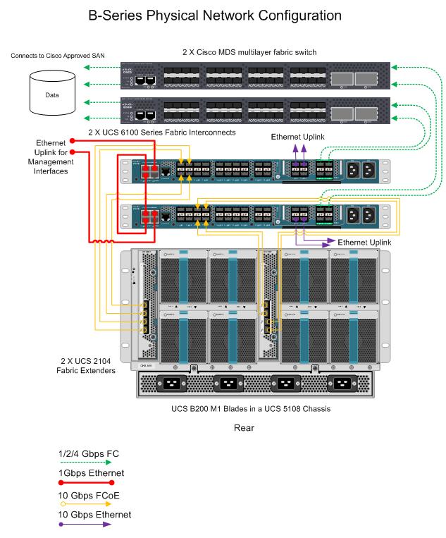
UCS B Series Physical Network Connections Design Example (top)
Figure 1 examples the connections between the following UCS Fabric components with redundant configuration for a Unified CCE on UCS B-series deployment:
- Two Cisco MDS multilayer fabric switches (Nexus 5/7 Series and 3rd Party SAN switches also supported as per Interop Matrix)
- Two Cisco UCS 6100 Series Fabric Interconnects (6200 Series also supported)
- Two Cisco UCS 2100 Series Fabric Extenders with minimum 2 10G links each (4 links illustrated) (2200 Series also supported)
- Dual 10 Gigabit Ethernet up-links from each Fabric that will be cross-connected to redundant Data Center switches. (See Up-links to Data Center Switches section below for more details).
Figure 1
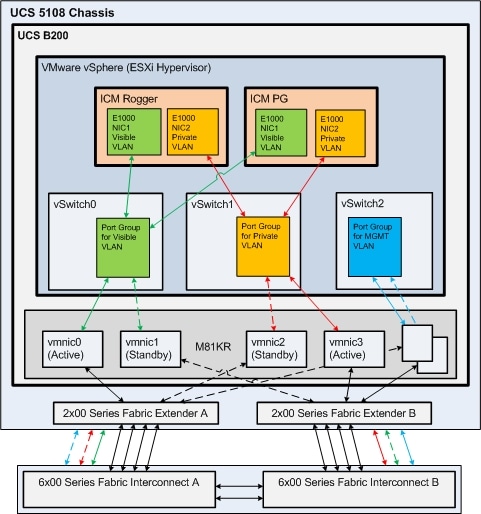
Unified CCE Network vSwitch Configuration for UCS B Series - Reference Design 1 (top)
Figure 2 illustrates the default design for Unified CCE on UCS B Series blades to meet Public and Private network communications requirements. This design requires the M81KR VIC.
Figure 2
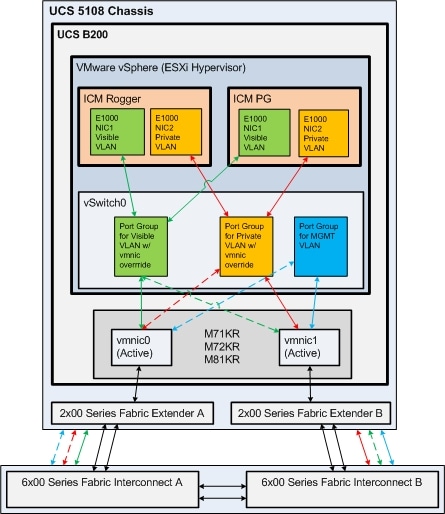
Unified CCE Network vSwitch Configuration for UCS B Series - Reference Design 2 (top)
Figure 3 illustrates an alternate design for Unified CCE on UCS B Series blades that uses a single vSwitch and an Active/Active VMNIC design. This design allows for the use of the M71KR and M72KR CNAs in addition to the M81KR, and is thus appropriate in an environment where you may have a mixture if CNA types installed across your blade infrastructure. This design requires vSwitch Port Group NIC Teaming override be used to control the flow of each VLAN through the Fabric Interconnects, rather than through the Active/Standby path control used in Reference Design 1 above. Please refer to VMware documentation and online help for futher information on how to enable Port Group override.
Figure 3
Creating the UCS Profile (top)
Understanding the service profile is key to understanding the blade management in the UCS. The service profile represents a logical view of a single blade server, without needing to know exactly which blade you are talking about. The profile object contains the server personality (identity and network information). The profile can then be associated with a single blade at a time. The following link provides a step by step guide on how to provision service profiles.
http://www.cisco.com/en/US/products/ps10281/products_configuration_example09186a0080af7515.shtml
Every server that is provisioned in the Cisco UCS is specified by a service profile. A service profile is a software definition of a server and its LAN and SAN network connectivity. In other words, a service profile defines a single server and its storage and networking characteristics. The UCS Manager software is embedded in the Cisco UCS 6100 Series Fabric Interconnects, which is also where the service profiles are stored. When a service profile is deployed to a server, UCS Manager automatically configures the server, adapters, fabric extenders, and fabric interconnects to match the configuration specified in the service profile. Automating the device configuration reduces the number of manual steps required to configure servers, network interface cards (NICs), host bus adapters (HBAs), and LAN and SAN switches.
This page does not provide a step by step guide on how to use UCS manager. However, it provides the necessary information to configure a service profile for Unified CCE.
Service Profile VLAN Configuration for Unified CCE in UCS Manager (top)
The service profile must have the complete and correct VLANs configured for Unified CCE Public and Private traffic.
The following shows an example of the VLANs needed for a Unified CCE deployment.
- One VLAN is needed for the Public Ethernet traffic
- One VLAN is needed for the Private Ethernet traffic
- One VLAN is needed for the VMkernel & Management traffic
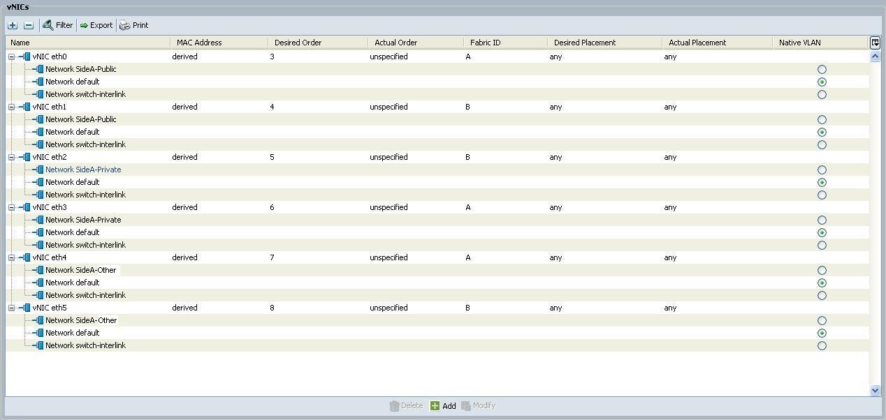
UCS Manager Profile for Reference Design 1 (top)
The following figure illustrates the six vNIC design used for Reference Design 1.
Note MAC addresses in UCS Manager for all vNICs, as the vNIC numbers do not map to same number vmnic in vSphere.
Note that in order to provision more than two interfaces per blade, the M81KR Virtual Interface Controller (VIC) must be used. The M71KR and M72KR Converged Network Adapters (CNA) are only capable of provisioning two interfaces and is limited to using Reference Design 2 as shown above.
Figure 4
UCS Manager Profile for Reference Design 2 (top)
The following figure illustrates the two vNIC design used for Reference Design 2.
Figure 5
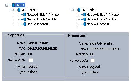
Note: VLAN for VMkernel & Management is not specifically depicted in this figure.
vSAN (top)
The service profile must have a vSAN configured for Unified CCE. The following shows an example of the vSAN needed for a UCCE deployment. The vSAN network ID must match the vSAN ID configured on the SAN devices for connectivity.
Figure 6

Configuring Up-link Ports on Data Center Switches for UCS B Series (top)
The following is an example of the port configuration for connection to the UCS Fabric Interconnects. For redundancy there must be at least two TenGigabitEthernet ports configured per UCS 6100 Series Fabric Interconnect cross connected to a Catalyst or Nexus Data Center switch pair. Gigabit Links may be used in certain cases where 10 Gigabit is not available in the Data Center, but a minimum of 4 links is required per Fabric (two dual 1 Gigabit port channels), with 8 recommended (two quad Gigabit port channels). This may require additional port licenses on the Fabrics.
Up-links to the UCS B Fabric Interconnects should use Virtual Switch Tagging (VST) mode, as exampled below.
interface TenGigabitEthernet2/1
description Fabric-Connect-A
switchport
switchport trunk encapsulation dot1q
switchport trunk allowed vlan 1,2,3,4
switchport mode trunk
no ip address
mls qos trust cos
spanning-tree portfast trunk/edge (actual command is IOS dependent)
Note: vPC/VSS and Etherchannel configuration not exampled, please refer to Cisco documentation for configuration best practices (see Cisco reference link below).
As exampled above, Cisco recommends auto negotiation for 10 and 1 Gigabit connections on both the network switch and the ESXi host adapters. Please see VMware reference below for more.
Where VLAN trunking is used to up-link to VMware, it is essential that the network configuration be implemented correctly. Testing has shown that improper configuration of VLAN trunking directly and negatively impacts performance of the system.
References:
Sample configuration of virtual switch VLAN tagging (VST Mode)
VMware Infrastructure 3 in a Cisco Network Environment
Troubleshooting network connectivity with Virtual Switch Tagging (VST) /
External Switch Tagging (EST) mode
Connectivity Solutions for the Cisco Unified Computing System
Configuring the speed and duplex of an ESX / ESXi host network adapter
As with all previous Unified CCE deployments, there must be dedicated public and private links between routers following supported models as defined in the Cisco Unified Contact Center Enterprise Solution Reference Network Design (SRND).
Configuring the vSphere vSwitch and vmnic Adapters (top)
For deploying Cisco Unified CCE on UCS B Series servers, configure the vSwitches and vmnic adapters as follows:
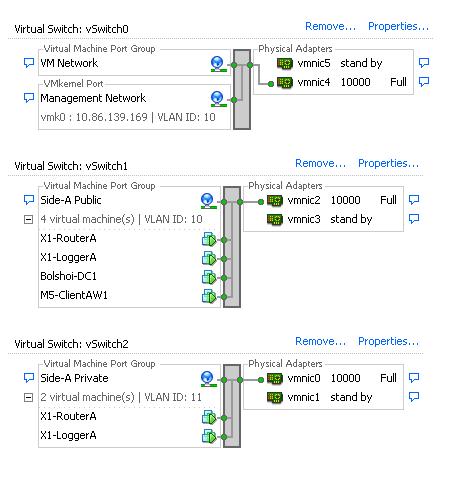
vSwitch and vmnic Adapter Configuration for Reference Design 1 (top)
For Reference Design 1 configurations that use the M81KR VIC, create 3 separate vSwitches with two A/B Fabric aligned pairs of vmnics in Active/Standby to control traffic pathing in alternating fashion for the Public and Private networks as illustrated in Reference Design 1 illustration above.
Assign physical adapters (vmnics) to vSwitches by MAC address to ensure that the correct interfaces created by the UCS profile are being assigned. Make sure that the Public and Private networks use alternate Fabrics (A/B) on their Active vmnic.
Figure 7
vSwitch and vmnic Adapter Configuration for Reference Design 2 (top)
In this design, a single vSwitch is used with two vmnics in Active/Active state.
Note: Figure incorrectly depicts Active/Standby.
Figure 8
Unified CCE on UCS C-Series Network Configuration (top)
The following section provides instructions on performing the network configuration needed to deploy Cisco Unified Contact Center Enterprise (Unified CCE) on UCS C-Series servers.
UCCE Design Guide can he download from this URL: http://www.cisco.com/c/en/us/support/customer-collaboration/unified-contact-center-enterprise/products-implementation-design-guides-list.html
Network Requirements for UCS C Series Servers (top)
The below design is the default and recommended for all Unified CCE deployments on UCS C series servers. Exampled in Figures 10 and 11 are two possible network side implementations of the same vSphere Hypervisor vSwitch design. This design calls for using the VMware NIC Teaming (without load balancing) of vmnic interfaces in an Active/Standby configuration through alternate and redundant hardware paths to the network, thereby preventing any single point of failure from affecting the Visible or Private network communications.
The network side implementation does not have to exactly match either of those illustrated below, but it must allow for redundancy and not allow for single points of failure affecting both Visible and Private network communications. There are more possible ways that this could be implemented in a supportable design than can be covered here.
Requirements:
- Ethernet interfaces must be Gigabit speed, and connected to Gigabit Ethernet switches. 10/100 Ethernet is not supported.
- No single point of failure is allowed to affect both the Active and Standby Visible network links or both the Visible and Private network communications between Unified CCE Side A and Side B servers at the same time.
- Cisco Stacking technology may not meet the high availability
requirements of Unified CCE network communications:
- A switch stack may not be used for both the Active and Standby Visible network uplinks from a single Unified CCE server in one physical switch within a stack.
- A switch stack may not be used for both the Active Visible and Active Private network uplinks from a single Unified CCE server in one physical switch within a stack.
- Active Visible and Active Private network uplinks from a single Unified CCE server must connect to separate physical switch within a stack.
- Network switches must be configured properly for connection to VMware. Refer to the VMware Knowledge Base for details on ensuring proper switch configuration to prevent Spanning Tree Protocol (STP) delay in failover/fallback scenarios.
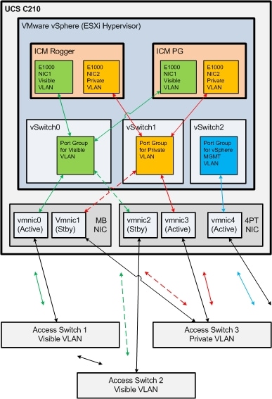
Figure 9
Figure 9 illustrates how to configure the vSwitches and vmnic adapters on a C-Series server using the redundant Active/Standby vSwitch NIC Teaming design.
Note: vmnic numbers in figure 9 do not match those illustrated in figures
10 and 11 below.
Note: Illustrations shows 10000 link speed, as this illustration is re-used
from UCS B example.
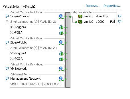
Figure 10
Figure 10 illustrates a sample UCS C-Series server network configuration for UCCE components that require both Public and Private network connections, and how that can work using the Active/Standby design with two network switches.
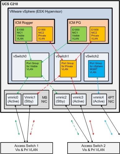
Figure 11
Figure 11 illustrates a sample UCS C-Series server network configuration for UCCE components that require both Public and Private network connections, and how that can be deployed using the Active/Standby design with three network switches.
Note: The Management VLAN and design is not fully illustrated as we do not have specific requirements for it to be deployed in any specific manner other than separate from the Visible and Private vSwitch & network interfaces. Please refer to VMware for best practices in deploying vSphere VMKernel/management interfaces to network.
Configuring Up-link Ports on Access Switches for UCS C Series (top)
The following are examples of data center access switch up-link port configurations for connecting to UCS C Series servers. You may use VST or EST VLAN tagging modes, but reference VST design is recommended. Ensure that whichever design you choose to use, that you have properly configured the correct corresponding setting between the network switches and the vSphere vSwitches. Please refer to reference Cisco and VMware documentation to help ensure proper design.
Virtual Switch VLAN Tagging Mode Example (VST): (Default Design)
interface GigabitEthernet1/1
description UCS-C-NIC1-PublicA
switchport
switchport trunk encapsulation dot1q
switchport trunk allowed vlan 1,2,3,4
switchport mode trunk
switchport nonegotiate
no ip address
spanning-tree portfast trunk/edge (actual command is IOS dependent)
External Switch VLAN Tagging Mode Example (EST):
interface GigabitEthernet1/1
description UCS-C-NIC1-PublicB
switchport
switchport access vlan 1
switchport mode access
no ip address
spanning-tree portfast
As exampled above, Cisco recommends auto negotiation for Gigabit connections on both the network switch and the ESXi host adapters. Please see VMware reference below for more.
It is essential that the network configuration be implemented correctly. Testing has shown that improper configuration of up-link ports can directly and negatively impact performance, operation and fault handling of the system.
References:
Sample configuration of virtual switch VLAN tagging (VST Mode)
Sample Configuration - ESX/ESXi connecting to physical switch via VLAN
access mode and External Switch VLAN Tagging (EST Mode)
VMware Infrastructure 3 in a Cisco Network Environment
Troubleshooting network connectivity with Virtual Switch Tagging (VST) /
External Switch Tagging (EST) mode
Connectivity Solutions for the Cisco Unified Computing System
Configuring the speed and duplex of an ESX / ESXi host network adapter
As with all previous Unified CCE deployments, there must be dedicated public and private links between routers following supported models as defined in the Cisco Unified Contact Center Enterprise Solution Reference Network Design (SRND).
Configuring the ESXi Host Network for the Virtual Machines (top)
To configure the network for VMs, you create a virtual switch connected to an Ethernet port on the server, and then associate the virtual machine's network adapter to this virtual switch.
To Add a vSwitch
- Login to the ESXi host using VMware Infrastructure Client
- Select the ESXi host
- Click on the Configuration tab
- Click on Hardware/Networking
- Click on Add Networking...
- Select Connection Types: Virtual Machine. Click Next.
- Select "Create a virtual switch" and select an associated VM NIC.
- Enter Port Group Properties/Network label: VM Network n, where n is an integer.(Example: "VM Network 1")
- Click on Finish.
To Associate a VM Network Adapter to Network Connection
- Edit virtual machine settings.
- Select the Network Adapter.
- Select a virtual switch from the Network Connection/network label. (Example: "VM Network 1")
- Click OK.