Installing the Chassis
Installation Options with Rack-Mount Kits, Racks, and Cabinets
The rack-mount kit enables you to install the switch into racks of varying depths. You can position the switch with easy access to either the port connections or the fan and power supply modules.
You can install the switch using the following rack-mount options:
-
Rack-mount kit (N9K-C9300-RMK) which you can order from Cisco.
You can install the switch in the following types of racks:
-
Open EIA rack
-
Perforated EIA cabinet
The rack or cabinet that you use must meet the requirements listed the in General Requirements for Cabinets and Racks section.
 Note |
You are responsible for verifying that your rack and rack-mount hardware comply with the guidelines that are described in this doc. |
Install a Rack
Before you install the switch, you must install a standard two- or four-post, 19-inch EIA data center rack (or a cabinet that contains such a rack) that meets the requirements listed in Overview of Racks.
Procedure
| Step 1 |
Bolt the rack to the concrete subfloor before moving the chassis onto it.
|
||||
| Step 2 |
If the rack has bonded construction, connect it to the earth ground. This action enables you to easily ground the switch and its components and to ground your electrostatic discharge (ESD) wrist strap to prevent damaging discharges when you handle ungrounded components before installing them. |
||||
| Step 3 |
Include one or two power sources at the rack. For AC power, provide a power receptacle. For DC power, provide a circuit breaker with terminals for connecting power cables.
|
Unpacking and Inspecting a New Switch
Before you install a new chassis, you need to unpack and inspect it to be sure that you have all the items that you ordered and verify that the switch was not damaged during shipment. If anything is damaged or missing, contact your customer representative immediately.
 Caution |
When you handle the chassis or its components, you must follow ESD protocol at all times to prevent ESD damage. This protocol includes but is not limited to wearing an ESD wrist strap that you connect to the earth ground. |
 Tip |
Do not discard the shipping container when you unpack the switch. Flatten the shipping cartons and store them. If you need to move or ship the system in the future, you will need this container. |
Procedure
| Step 1 |
Compare the shipment to the equipment list that is provided by your customer service representative and verify that you have received all of the ordered items. The shipment should include the following:
|
| Step 2 |
Check the contents of the box for damage. |
| Step 3 |
If you notice any discrepancies or damage, send the following information to your customer service representative by email:
|
Planning How to Position the Chassis in the Rack
The switch is designed so that you can have coolant air flow through the switch in one of the two following directions:
-
Enter the port side and exhaust out the power supply side (port-side intake airflow)
-
Enter the power supply side and exhaust out the port side (port-side exhaust airflow)
For port-side intake airflow, the switch must have port-side intake fan and AC power supply modules with one or more of the following colorings:
-
Burgundy coloring on fan modules and AC power supplies
-
Green coloring on DC power supplies
-
White coloring on 1200-W HVAC/HVDC power supplies (dual-direction airflow power supplies with their airflow direction set by the fan modules)
For port-side exhaust airflow, the switch must have port-side exhaust fan and AC power supply modules with one or more of the following colorings:
-
Blue coloring on fan modules and AC power supplies
-
Gray coloring on DC power supplies
-
White coloring on 1200-W HVAC/HVDC power supplies (dual-direction airflow power supplies with their airflow direction set by the fan modules)
You can plan the positioning of the switch so that its ports are located close to ports on connected devices or so that the fan and power supply modules are conveniently located in a maintenance aisle, and then order the modules that move coolant air in the appropriate direction from the cold aisle to the hot aisle.
Note |
All fan and power supply modules in the same switch must operate with the same direction of airflow and the air intake portion of the switch must be located in a cold aisle. |
Installing the Chassis in a Two-Post Rack
Before you install the chassis, be sure that the rack is fully secured to the data center floor.
You must attach mounting brackets to the chassis before mounting the chassis.
Attaching Center-Mount Brackets to the Chassis
You need to attach a right-angled bracket to each side of the chassis. This bracket centers the chassis and secures it in place on a two-post rack.
 Warning |
Statement 1006—Chassis Warning for Rack-Mounting and Servicing To prevent bodily injury when mounting or servicing this unit in a rack, you must take special precautions to ensure that the system remains stable. The following guidelines are provided to ensure your safety:
|
Before you begin
-
You must separately order the center-mount brackets if you are installing the chassis in a two-post rack. These brackets do not ship with the chassis unless you specifically order them.
-
You must have the following tools and equipment:
-
Manual Phillips-head torque screwdriver
-
Center-mount bracket kit
-
Procedure
| Step 1 |
Align one of the two center-mount brackets on the left or right side of the chassis and be sure that the angled portion is facing the front of the chassis (see the following figure). Be sure to align four of the screw holes on the larger side of the bracket with the four screw holes near the center of the left or right side of the chassis. 
|
||||
| Step 2 |
Use four M4 x 8 mm screws to attach the bracket to the chassis. Tighten each screw to 11 to 15 in-lb (1.2 to 1.7 N·m). |
||||
| Step 3 |
Repeat Steps 1 and 2 to attach the second center-mount bracket to the other side of the chassis. |
What to do next
You are ready to mount the chassis to the two-post rack.
Installing the Chassis in a Two-Post Rack
You need to position the chassis near the top of the rack with the power supply and fan modules in the appropriate aisle for their required airflow. If the fan modules have a blue coloring for port-side exhaust airflow, then you must position the modules by the cold aisle. If the fan modules have a burgundy coloring for port-side intake airflow, you must position the modules by the hot aisle.
Note |
Power supply modules must have the same airflow direction as the fan modules. |
Note |
Power supply modules must have the same airflow direction as the fan modules but might have different coloring if they use DC power (green coloring for port-side intake airflow or gray coloring for port-side exhaust airflow). HVAC/HVDC power supplies with white coloring use the same direction of airflow as used by the fan modules. |
Warning |
Statement 1074—Comply with Local and National Electrical Codes To reduce risk of electric shock or fire, installation of the equipment must comply with local and national electrical codes. |
Warning |
Statement 1032—Lifting the Chassis To prevent personal injury or damage to the chassis, never attempt to lift or tilt the chassis using the handles on modules (such as power supplies, fans, or cards); these types of handles are not designed to support the weight of the unit. |
Before you begin
-
Make sure that the two-post rack is properly installed and secured to the concrete subfloor.
-
Make sure that two center-mount brackets are securely fastened to the middle of each side of the chassis.
-
Make sure that you have six customer-supplied rack-mount screws (typically M6 x 10 mm or the appropriate screw for the vertical mounting rails on the rack).
-
You have at least two people to install the chassis.
Warning |
Statement 1006—Chassis Warning for Rack-Mounting and Servicing To prevent bodily injury when mounting or servicing this unit in a rack, you must take special precautions to ensure that the system remains stable. The following guidelines are provided to ensure your safety:
|
Procedure
| Step 1 |
Use one person to position the chassis so that it is near the top of the rack with the fan and power supply modules in the appropriate aisle and the center-mount bracket has its screw holes aligned to screw holes on the two-post rack. If these modules have a blue or gray coloring for port-side exhaust airflow, then you must position the modules by the cold aisle. If the modules have a burgundy or green coloring for port-side intake airflow, you must position the modules by the hot aisle. 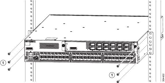
|
||||
| Step 2 |
Use the second person to secure the three customer-supplied rack-mount screws (typically M6 x 10 mm or other appropriate screws for the rack) on each center-mount bracket to attach the chassis to the rack. Tighten each screw to the appropriate torque setting for the screws (for M6 x 10 mm screws, use 40 in-lbs [4.5 N·m] of torque). |
Installing the Chassis in a Four-Post Rack
Before you install the chassis, be sure that the rack is fully secured to the data center floor.
Installing the Switch using the N9K-C9300-RMK Rack-mount Kit
Attaching the Bottom-Support Rails to the Rack
The switch chassis that you are installing ships with two adjustable bottom-support rails that you can attach to a four-post rack to hold the chassis. Each of these bottom-support rails has two pieces—one that slides into the other so that you can adjust them to fit racks with front and rear mounting posts that are spaced less than 36 inches (91 cm). On each bottom-support rail, the rail half that slides into the other rail includes a chassis stop that fits into the module end of the chassis. Depending on direction of the chassis airflow, you need to position the rail half with the chassis stop so that the fan and power supply modules end up in the appropriate aisle as follows:
-
Port-side intake (burgundy coloring for fan modules) airflow requires that the bottom-support rail with the chassis stop be located on the hot aisle side of the rack.
-
Port-side exhaust (blue coloring for fan modules) airflow requires that the bottom-support rail with the chassis stop be located on the cold aisle side of the rack.
Warning |
Statement 1074—Comply with Local and National Electrical Codes To reduce risk of electric shock or fire, installation of the equipment must comply with local and national electrical codes. |
Before you begin
Before you can install the bottom support rails for the chassis, you must do the following:
-
Verify that a four-post rack or cabinet is installed.
-
If any other devices are stored in the rack or cabinet, verify that the heavier switches are installed below lighter switches.
-
Verify that the bottom-support rails kit is included in the switch accessory kit.
-
Verify that you have 8 screws for attaching the bottom support brackets to the racks (typically M6 x 10 mm screws or the screw appropriate for the vertical mounting rails on the rack.
Warning |
Statement 1006—Chassis Warning for Rack-Mounting and Servicing To prevent bodily injury when mounting or servicing this unit in a rack, you must take special precautions to ensure that the system remains stable. The following guidelines are provided to ensure your safety:
|
Procedure
| Step 1 |
Look at the fan and power supply modules installed in the chassis to determine how you must position the bottom-support rails on the rack.
|
||||||||
| Step 2 |
Separate the two sliders that make up one bottom-support rail and position the half with the chassis stop by the appropriate aisle for the fan and power supply modules. Also make sure that there is at least 1 rack unit open above the bottom-support rails so that you can easily install the chassis. |
||||||||
| Step 3 |
Use two customer-supplied screws (typically M6 x 10 mm screws) to attach the bottom-support rail half to the vertical mounting rails on the rack post. Tighten each screw to the appropriate torque setting for the screws (for M6 x 10 mm screws, use 40 in. lbs [4.5 N·m] of torque). |
||||||||
| Step 4 |
Slide the other half of the bottom-support rail onto the attached half of the rail set and use two customer supplied screws (typically M6 x 10 mm screws) to secure that portion to the vertical mounting rails on the rack. Tighten each screw to the appropriate torque setting for the screws (for M6 x 10 mm screws, use 40 in. lbs [4.5 N·m] of torque). 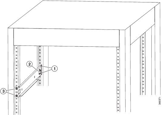
|
||||||||
| Step 5 |
Repeat Steps 2 and 3 to attach the other expanding bottom-support rails to the other side of the rack.
|
What to do next
You are ready to install two front-mount brackets on the chassis.
Attaching Front-Mount Brackets to the Chassis
You need to attach a right-angled bracket to each side of the chassis. This bracket holds the chassis in place on a four-post rack.
Before you begin
-
You must have the following tools and equipment:
-
Manual Phillips-head torque screwdriver
-
Front-mount brackets (2) and screws (4) (found inside the switch accessory kit)
-
Procedure
| Step 1 |
Align the two holes in one side of one of two front-mount brackets to two holes on the left or right side of the chassis (see the following figure). Be sure that the other side of the bracket is facing toward the front (port end) of the chassis. 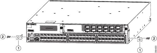
|
||||
| Step 2 |
Use two M4 x 6 mm screws to attach the bracket to the chassis. Tighten each screw to 11 to 15 in-lb (1.2 to 1.7 N·m). |
||||
| Step 3 |
Repeat Steps 1 and 2 to attach the second center-mount bracket to the other side of the chassis. |
What to do next
You are ready to mount the chassis to the four-post rack.
Installing the Chassis in a Four-Post Rack
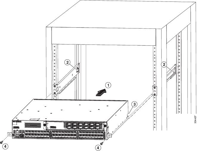
You need to slide the chassis onto the bottom-support rails so that the power supply end locks onto the chassis stops at the end of the rails and so that the front-mount brackets on the chassis come into contact with the front-mount rails on the rack.
Warning |
Statement 1074—Comply with Local and National Electrical Codes To reduce risk of electric shock or fire, installation of the equipment must comply with local and national electrical codes. |
Warning |
Statement 1032—Lifting the Chassis To prevent personal injury or damage to the chassis, never attempt to lift or tilt the chassis using the handles on modules (such as power supplies, fans, or cards); these types of handles are not designed to support the weight of the unit. |
Before you begin
-
Make sure that the four-post rack is properly installed and secured to the concrete subfloor.
-
Make sure that the bottom-support rails are installed so that the fan modules will be in the appropriate aisle as follows:
-
Burgundy (port-side intake airflow) fan modules are positioned in a hot aisle (the chassis stop on the bottom-support rails is positioned by the hot aisle).
-
Blue colored (port-side exhaust airflow) fan modules are positioned in a cold aisle (the chassis stop on the bottom-support rails is positioned by the cold aisle).
-
-
Make sure that two front-mount brackets are securely fastened to the sides of the chassis at the port end.
-
Make sure that you have two customer-supplied rack-mount screws (M6 x 10 mm or appropriate screw for the vertical mounting rails on the rack).
Warning |
Statement 1006—Chassis Warning for Rack-Mounting and Servicing To prevent bodily injury when mounting or servicing this unit in a rack, you must take special precautions to ensure that the system remains stable. The following guidelines are provided to ensure your safety:
|
Procedure
| Step 1 |
Slide the power supply end of the chassis onto the bottom-support rails that are installed on the rack. Be sure that the sides of the chassis by the power supplies clips into the chassis stops on the bottom-support rails and the front-mount brackets come in contact with the rack (see the following figure).
|
||||||||||
| Step 2 |
Use a customer-supplied rack-mount screw (an M6 x 10 mm screw or other appropriate screw for the rack) to attach each of the two mounting brackets on the chassis to the rack and tighten each screw to the appropriate torque setting for the screw (for M6 x 10 mm screws, use 40 in-lbs [4.5 N·m] of torque). |
Grounding the Chassis
The switch chassis is automatically grounded when you properly install the switch in a grounded rack with metal-to-metal connections between the switch and rack.
You can also ground the chassis, which is required if the rack is not grounded, by attaching a customer-supplied grounding cable. Attach the cable to the chassis grounding pad and the facility ground.
Warning |
Statement 1024—Ground Conductor This equipment must be grounded. To reduce the risk of electric shock, never defeat the ground conductor or operate the equipment in the absence of a suitably installed ground conductor. Contact the appropriate electrical inspection authority or an electrician if you are uncertain that suitable grounding is available. |
Warning |
Statement 1046—Installing or Replacing the Unit To reduce risk of electric shock, when installing or replacing the unit, the ground connection must always be made first and disconnected last. |
Before you begin
Before you can ground the chassis, you must have a connection to the earth ground for the data center building.
Procedure
| Step 1 |
Use a wire-stripping tool to remove approximately 0.75 inch (19 mm) of the covering from the end of the grounding wire. We recommend 6-AWG wire for the U.S. installations. |
||||||||
| Step 2 |
Insert the stripped end of the grounding wire into the open end of the grounding lug. Use a crimping tool to crimp the lug to the wire, see the following figure. Verify that the ground wire is securely attached to the grounding lug by attempting to pull the wire out of the crimped lug. 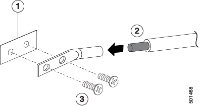
|
||||||||
| Step 3 |
Secure the grounding lug to the chassis grounding pad with two M4 screws, see the previous figure. Tighten the screws to 11 to 15 in-lb (1.24 to 1.69 N·m) of torque. |
||||||||
| Step 4 |
Prepare the other end of the grounding wire and connect it to the facility ground. |
Powering Up the Switch
To power up the switch, you must connect the power supplies to one or two power sources. The number of power sources used depends on the type of power redundancy that you require as follows:
-
For no power redundancy, connect only the power supplies to one power source.
-
For n+1 redundancy, connect the power supplies to one or two power sources.
-
For n+n redundancy, connect each power supply to a different power source (two power sources required).
no_notes |
Statement 7012—Equipment Interfacing with AC Power Ports This equipment shall be connected to AC mains provided with a surge protective device (SPD) at the service equipment complying with NFPA 70, the National Electrical Code (NEC). |
Warning |
Statement 1004—Installation Instructions Read the installation instructions before using, installing or connecting the system to the power source. |
Warning |
Statement 1018—Supply Circuit To reduce risk of electric shock and fire, take care when connecting units to the supply circuit so that wiring is not overloaded. |
Before you begin
-
Switch installed in a rack and connected to an earth ground
-
Recommended power cable for your nation or region
-
Power source with the required amperage located within reach of the power cable being used
Procedure
|
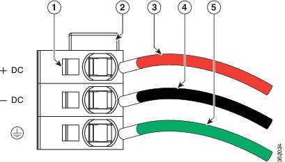
Connect each power supply to a power source as follows:
|