Cisco Nonstop Forwarding (NSF) with Stateful Switchover (SSO) provides increased network service availability and protection against unplanned downtime due to hardware or software problems. Deploying NSF/SSO at critical network locations will improve system and service availability while preparing to take advantage of future capabilities that target planned downtime through In Service Software Upgrade (ISSU).
All organizations, whether an Enterprise seeking to provide network access to critical business systems, or Service Providers seeking to offer unsurpassed network service and connectivity to their customers, understand that reducing downtime due to component failure is an operational necessity. Cisco customers go to great lengths to create redundant network designs and ensure their operational procedures produce the highest service availability possible according to the business requirements and budget allotted.
Cisco NSF/SSO evolved from a series of progressive enhancements to reduce the impact of specific network outages. Cisco NSF/SSO builds on the earlier work known as Route Processor Redundancy (RPR) and RPR Plus (RPR+). Through the use of redundant intra-chassis hardware (redundant route processors) and the separation of the control plane from the data plane, continuous packet forwarding with zero packet loss can now be achieved, even if a hardware or software problem causes a route processor failure.
This document is meant as an aid to the network design and the network operations staff who are intent on increasing availability by deploying Cisco NSF/SSO. The first section will describe the target deployment points within the network. Sections two and three will review the operational characteristics of Stateful Switchover and Nonstop Forwarding. Section four will describe the implementation procedures that will ensure a successful deployment.
Note: Throughout this document, the term "Route Processor" is used to describe the route processing engine on all networking devices, regardless of the hardware designation, unless otherwise noted. For example, on the Cisco 10000 Series Internet Router the Route Processor is referred to as the Performance Routing Engine (PRE), on the Cisco 12000 Series Internet Router the Route Processor is referred to as the Gigabit Route Processor (GRP) or the Performance Route Processor (PRP), the Cisco Catalyst® 6500 Series Switches and Cisco 7600 Series Routers use the term Supervisor, and on the Cisco 7500 Series Router the Route Processor is referred to as the Route Switch Processor (RSP).
NSF/SSO DEPLOYMENT
At first it may seem that all network nodes would benefit from the increased resiliency provided by Cisco NSF/SSO. However, in practice it is the edge devices that gain the most benefit from this feature. Single points of failure will tend to exist at the network edge boundaries. Further, the Service Provider edge will tend to have more single points of failure because of the economy of scale the services business is built on. The tendency is to design path redundancy among higher tier and backbone nodes such that a failure to a single node will not impact service. Therefore, higher tier and backbone nodes are not typically outfitted with redundant intra-chassis route processors and network resilience; instead it depends on routing convergence to an alternate path. Fast IP routing convergence offers availability improvements by detecting link or node failures immediately and routing traffic quickly to an alternate path. Multiprotocol Label Switching (MPLS) VPN networks incorporate such features as traffic engineering and fast re-route with link and node protection in the core to achieve path resiliency. Although routing protocol convergence directly impacts network service availability, it can be a complex subject and will not be the focus of this document. For information relative to routing protocol timer manipulation and NSF/SSO, please refer to the Cisco NSF and Timer Manipulation for Fast Convergence-High Availability document: http://www.cisco.com/en/US/technologies/tk869/tk769/technologies_white_paper09186a00801dce40_ps6550_Products_White_Paper.html.
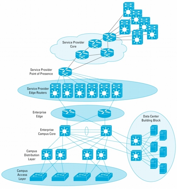
Figure 1. Primary Deployment Points for Cisco NSF/SSO
Figure 1 illustrates the prime target deployment points for Cisco NSF/SSO. As shown by the highlighted circles, deployment of NSF/SSO at the edge of Service Provider networks will provide the most benefit. Nonstop Forwarding ensures that customers are shielded from the affects of a route processor in the Service Provider edge router going offline for some reason, whether it is for maintenance or because of some failure. In particular, customers or networks that interconnect to the Service Provider at only a single edge router gain the most. The Service Provider edge router represents a single point of failure for these customers, and without this capability any impact to that node halts all traffic flow using that path. With Non-Stop Forwarding, traffic flow continues during a switchover to the redundant route processor within the chassis, leading to better service and less network disruption and routing protocol fluctuation.
In many networks, additional benefit is seen at other locations within a topology. For instance, Enterprises will see benefit by deploying NSF/SSO at the edge boundary to their Service Provider, because these devices typically provide critical network services and loss of capacity or packet loss due to reconvergence is significant. The availability of NSF/SSO for the Cisco Catalyst 6500 Series Switch enables deployment on key data center distribution layer devices and at the campus access layer, where single point of failure connections exist. See the section NSF/SSO in Campus Networks for more details.
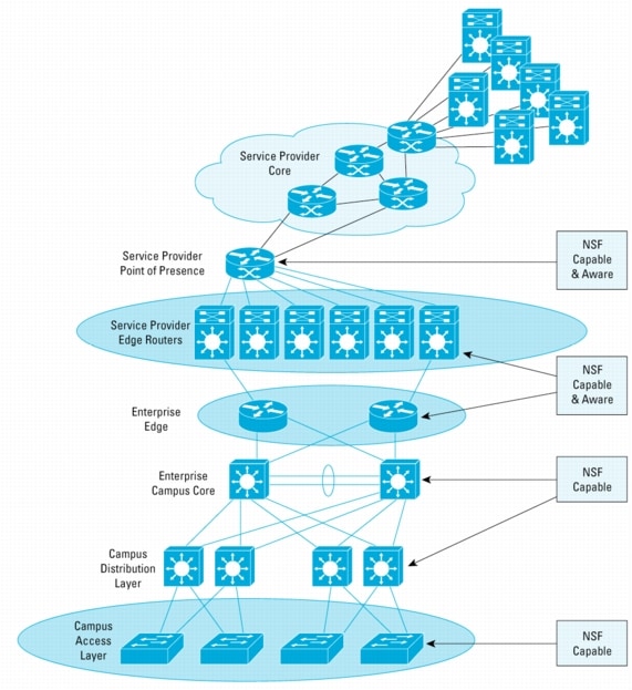
Note that the neighbor nodes play a role in the Cisco Nonstop Forwarding function (see Figure 2). A node that is capable of continuous packet forwarding during a route processor switchover is NSF-capable. An adjacent or routing protocol peer node must be NSF-aware to gain the greatest benefit from NSF/SSO deployment. Although it is not absolutely required for implementation, only limited benefit will be achieved unless routing peers are aware of the ability of the restarting node to continue packet forwarding and assist in restoring and verifying the integrity of the routing tables after a switchover. This will be explained during description of the operational details of NSF for each routing protocol.
Cisco Nonstop Forwarding and Stateful Switchover are designed to be deployed together. NSF relies on SSO to ensure that links and interfaces remain up during switchover, and that lower layer protocol state is maintained. NSF is, however, configured separately and it is possible to enable SSO without NSF.
Figure 2. NSF-Aware Devices Cooperate with NSF-Capable Devices
NSF/SSO IN CAMPUS NETWORKS
Campus networks have typically been designed with high redundancy and an abundance of bandwidth. Within the campus, dual equal cost paths and fast convergence allows traffic to take alternate paths in the event of failure to nearly any link or component. However, there are places where NSF/SSO offers advantages in terms of continuous connectivity, lower packet loss, and consistent path flow through nodes providing specific network services.
Figure 3. NSF-Aware Devices Cooperate with NSF-Capable Devices
In Figure 3 the circles highlight the places where NSF/SSO is expected to offer the most benefit.
The first location to consider is the access layer. In larger Enterprises, availability is often improved through the use of common equipment and modules to simplify the design, ensure consistent operation, and minimize sparing needs. With Cisco Catalyst 6500 Series or 4500 Series Switch equipment providing wiring closet connectivity for end stations and IP telephony, SSO offers protection against failure due to the Supervisor or loss of service because of software problems. The access layer typically provides Layer 2 services, with redundant switches making up the distribution layer. The Layer 2 access layer can benefit from SSO deployed without NSF. Some Enterprises have deployed Layer 3 routing at the access layer. In that case, NSF/SSO can be used.
Another location to consider is the campus metropolitan network edge. In many Enterprises, the campus is an extended one, where multiple buildings are interconnected. Sometimes a metropolitan-area network is created with dual routers or switches interconnecting each building or site. Metropolitan-area services may be provided by a Service Provider, interconnected through dark fiber or made up of Enterprise-owned fiber paths. In either case, the campus edge where each site connects to the metro net becomes more critical and will benefit from NSF/SSO.
Lastly, equipment used to front-end data centers, servers, computing clusters, and mainframes will benefit from NSF/SSO. Here it becomes particularly beneficial to preserve traffic paths that pass through hardware- and software-based IP services equipment or blades such as firewalls, content management systems, load-balancing systems, etc.
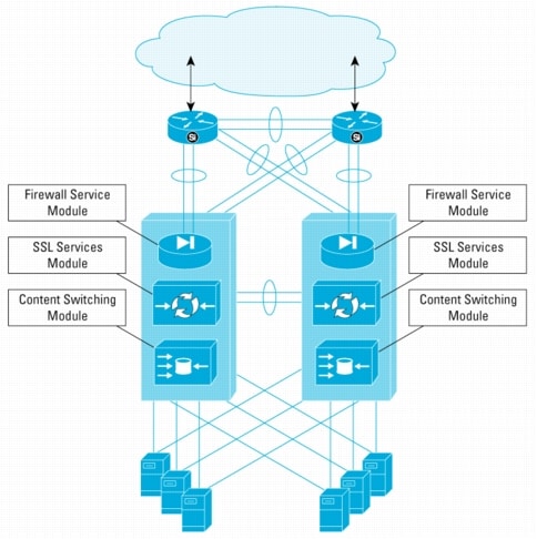
Figure 4. NSF/SSO in the Data Center
Figure 4 illustrates the data center design. The figure shows an example where dual Cisco Catalyst 6500 Series switches are deployed with integrated Service Modules. Specifically, the Firewall Services Module, SSL Services Module, and the Content Switching Services Module are used to provide vital services for traffic destined for applications on the connected servers.
In this environment, it is beneficial for traffic to continue to flow along consistent paths even in the event of a possible Supervisor failure on one of the Cisco Catalyst 6500 Series switches. With support for NSF/SSO, the effect of failures and network reconvergence are minimized and the amount of traffic loss and Mean Time to Repair (MTTR) are lowered. Protection from critical failure that affects a service module, the power to a chassis, or a complete chassis failure is still provided by the redundant switch operating in parallel.
OPERATIONAL CONSIDERATIONS FOR SSO
Cisco Stateful Switchover relies on two other Cisco IOS® Software Infrastructure subsystems called the Redundancy Facility and theCheckpoint Facility. Software that controls individual protocols such as PPP, high-level data link control (HDLC), Frame Relay, etc. use the Checkpoint Facility and the Redundancy Facility to ensure that the link state and Layer 2 protocol details are mirrored on the standby Route Processor. This helps links to remain operational during a Route Processor switchover.
Previous redundancy modes such as RPR did not exhibit this quality. In RPR mode, the standby Route Processor loads a Cisco IOS Software image at power on and initializes itself in standby mode. The startup configuration is synchronized to the standby Route Processor, but incremental changes are not. In the event of a switchover, the standby Route Processor reinitializes itself as the active Route Processor, reloads all the line cards, and restarts the system. Because all line cards are reloaded, adjacent routers detect the physical link failure for most types of point-to-point connections. In RPR+ mode, the standby Route Processor is fully initialized and configured. This allows RPR+ to dramatically shorten the switchover time if the active Route Processor fails, or if a manual switchover is performed. Both the startup and running configurations are continually synchronized from the active to the standby Route Processor, and the line cards are not reset during a switchover. The interfaces remain up during this transfer, so neighboring routers do not detect a physical link flap (the link does not go down and back up). However, some Layer 2 protocols will still fail because line card, protocol, and application state information are not synchronized. With redundancy mode set to SSO, line card, protocol, and application state information are synchronized and the redundant Route Processor provides a "hot" standby ready to take over immediately.
Currently, for synchronization to be performed using SSO, both Route Processors must run the same level of software release. Development of In Service Software Upgrade (ISSU) is under way and, when available, will negate this restriction and allow software upgrades to occur without impacting service by taking advantage of NSF/SSO.
Operationally, a major consequence and benefit of SSO is that adjacent devices do not see a link failure when the Route Processor switches from the primary to the hot standby Route Processor. This applies to Route Processor switchovers only. If the entire chassis lost power or failed, or a line card failure occurred, the link(s) would fail, and the peer would detect such an event. Of course, this assumes point-to-point Gigabit Ethernet interfaces, packet over SONET (POS) interfaces, etc. where link failure is detectable. Even with NSF enabled, physical link failures are still detectable by a peer and override NSF awareness.
Protocol Specificities for SSO
SSO-supported line protocols and applications are SSO-aware. A Cisco IOS Software feature or protocol is SSO-aware if it maintains, either partially or completely, undisturbed operation through a Route Processor switchover by using the facilities provided by the Redundancy Facility and Checkpoint Facility. State information for SSO-aware protocols and applications (such as PPP, Frame Relay, Asynchronous Transfer Mode (ATM), and Simple Network Management Protocol (SNMP)) is synchronized from active to standby to achieve stateful switchover for those protocols and applications.
The dynamically created state of protocols and applications that are not SSO-aware is lost on switchover and must be reinitialized and restarted there. These protocols and applications may encounter some period of packet loss until the state information is established or reconstructed.
As of October 2004, SSO provided support for PPP, Multilink Point-to-Point Protocol (MLPPP), high-level data link control (HDLC), Frame Relay, ATM, and Ethernet. Switching products also include support for the features and protocols listed in Table 1.
Table 1. Switching Feature Support of SSO
Link Negotiation
VLAN Trunking Protocol (VTP)
Dynamic Trunking Protocol (DTP)
Virtual LANs (VLANs)
802.1Q
Port Aggregation Protocol (PAgP)
VLAN trunks
Layer 2 protocol tunneling
MAC Move Notification
Spanning Tree Protocol
802.1Q Tunneling
Flow Control & Traffic Storm Control
Address Resolution Protocol (ARP)
Bridge Groups
Voice VLAN with Inline Power
Cisco Discovery Protocol
Port Security
802.1x
(Remote) Switch Port Analyzer (SPAN/RSPAN)
Unidirectional
Link Detection Protocol (UDLD)
Link Aggregation Control Protocol (802.3ad-LACP)
Internet Group Management Protocol (IGMP) Snooping
Products also maintain configuration and state information to allow transparent failover at Layer 4. This includes maintaining Quality of Service (QoS), security features, and access control lists (ACLs).
For detailed information about the state synchronization, restrictions, and configuration of each specific protocol, please refer to the appropriate Cisco documentation.
OPERATIONAL CONSIDERATIONS FOR NSF
Cisco NSF can be considered a Layer 3 routing redundancy feature. NSF takes advantage of the separation of the control plane from the forwarding plane. The control plane is the routing protocol intelligence, and the forwarding plane switches packets using hardware acceleration where available. NSF is tightly coupled with Cisco Express Forwarding. Distributed routing hardware such as Cisco 12000 and Cisco 7600 series routers and Cisco Catalyst 6500 Series switches download Cisco Express Forwarding information in the form of a forwarding information base (FIB) to the line cards. That way, the line cards can continue to forward traffic using the routing information they have, while the Route Processor switchover occurs.
NSF also uses the Checkpoint Facility and Redundancy Facility to replicate the state information of Cisco Express Forwarding to the standby Route Processor. When the hot standby Route Processor takes over and becomes `active', NSF-capable and -configured routing protocols reform adjacencies with their neighbors and exchange routing information. After routing information exchange, the routing information base (RIB) is verified with the FIB and updated, if necessary, to ensure accuracy and synchronization of routing information with the peers.
Note that the routing protocol adjacency is lost when the primary Route Processor is down and reestablished after the standby Route Processor becomes active. And subsequently, routing protocol information is exchanged with the peers. For this to occur and to ensure that peer or adjacent routers continue to forward traffic to the router undergoing a switchover, routing protocol extensions are used.
From an operational and deployment perspective, this requires the adjacent routers to support the routing protocol extensions. The extensions to routing protocols allow a neighbor to be aware in advance that its peer can continue forward packets, but may bring its adjacency down for a brief period and request routing protocol information to be sent. A router that has the capability for continuous forwarding during a switchover is NSF-capable. Devices that support the routing protocol extensions to the extent that they continue to forward traffic to a restarting router are NSF-aware. A Cisco device that is NSF-capable is also NSF-aware. Some software versions and Cisco products support NSF awareness without the support to be NSF-capable.
Protocol Specificities for NSF
As mentioned previously, Cisco Nonstop Forwarding does not maintain a continuously active control plane during switchover. Instead, the forwarding plane uses known routes while the routing protocol information is being restored after switchover. In Cisco networking devices, packet forwarding is provided by Cisco Express Forwarding. Cisco Express Forwarding maintains the FIB and uses the FIB information that was current at the time of the switchover to continue forwarding packets during a switchover. The ability to continue packet forwarding eliminates downtime during the switchover.
Cisco NSF supports the Border Gateway Protocol (BGP), Intermediate System-to-Intermediate System (IS-IS), Open Shortest Path First (OSPF), and EIGRP routing protocols. Cisco NSF also includes support for multi-protocol label switching (MPLS) related protocols (please refer to the appropriate documentation for product and release availability). Each protocol depends on Cisco Express Forwarding to continue forwarding packets during switchover, while the routing protocols rebuild the Routing Information Base (RIB).
Cisco current implementation of Nonstop Forwarding was designed with the following requirements in mind:
• Provide scalability to meet the needs of Cisco customers
• Be deployable across a number of Cisco products
• Maintain network integrity across several failure scenarios
Cisco worked with the network community and the IETF to promote several extensions to widely used routing protocols, producing an effective solution. The standards and drafts that form the basis of the protocol extensions are summarized in the section: Related Standards and Drafts.
The next sections describe the protocol extensions and implementation for each of the supported routing protocols.
BGP NSF
Cisco support for BGP Nonstop Forwarding (also called Graceful Restart) follows the implementation specification described in the IETF proposed standard. According to this implementation, to achieve continuous packet forwarding the following conditions must be met:
• The NSF-capable router and the peer router must each agree to support BGP Graceful Restart.
• The peer router must not prematurely declare the NSF-capable router as unavailable.
• The peer router must not communicate any state change in the NSF-capable router to any of its peers. This avoids the networkwide detrimental effect on performance associated with the sudden failure of a router.
• The peer router must send BGP updates to help the restarting NSF-capable router to reacquire its BGP RIB.
• The peer router must signal the completion of the initial routing update by sending the End-of-RIB marker.
• In the interim (before the restarting NSF-capable router has reacquired the routing information), the peer router must mark any routes associated with the restarting router as "stale", but continue to use those routes for packet forwarding.
The protocol modifications begin when the initial BGP connection is established. Both the NSF-capable router and its peer indicate their understanding of the BGP Graceful Restart mechanism by exchanging a new BGP capability (#64) during the initial BGP OPEN that establishes the session.
Note that the router will send Capability 64, regardless of whether it is NSF-capable. Capability 64 does not alone indicate restartability. It can indicate that the router in question has implemented the BGP enhancements specified in the IETF draft. Thus, a Cisco 7200 Series Router that is configured for BGP graceful-restart will still advertise Capability 64 to its peers, even though it does not support dual RPs and cannot restart BGP.
Additionally, the NSF-capable router will provide a list of Address Family Identifiers (AFI) and Subsequent Address Family Identifiers (SAFI), for which it has the capability to maintain forwarding state across a BGP Restart. The AFI and SAFI indicate different types of protocols, for which BGP can carry information. This would include protocol support such as IPv4, IPv6, MPLS, and Unicast/Multicast routing.
This section offers an example of the BGP Graceful Restart procedures in action during a Route Processor switchover. Figure 5 illustrates the BGP protocol extension procedures, where R1 is the restarting router, and R2 is a peer (also called the receiving router). Remember, the goal is to restart a BGP session without the peers of the NSF-capable router redirecting traffic around the restarting router.
1. The BGP process of router R1 begins and establishes a peering relationship with router R2. It sends an OPEN message to R2. The OPEN message includes the Graceful Restart Capability (Code 64), Address Family of IPv4, and Subsequent Address Family ID of unicast. Because R2 supports Graceful Restart, it also sends an acknowledgement through its own OPEN Message, which contains GR=64 and AF=IPv4.
2. A Route Processor switchover occurs, and the router R1 BGP process restarts on the newly active Route Processor. R1 does not have a routing information base on this Route Processor and must reacquire it from its peer routers. R1 will continue to forward IP packets destined for (or through) peer routers (R2) using the last updated FIB and Cisco Express Forwarding table.
3. When the receiving router (R2) detects that the TCP session between it and the restarting router is cleared, it immediately marks routes, learned from the restarting router, as STALE. R2 marks routes learned only from R1 as STALE. If R2 had other peers, then the routes learned from those peers would remain in the UP state. Router R2 also initializes a Restart-timer for the restarting router. The default setting for this timer is 120 seconds. The Restart-timer is the amount of time that a receiving router will wait for an OPEN message from the restarting router. A receiving router will remove all STALE routes unless it receives an OPEN message from the restarting router within the specified Restart-time. When R2 receives the R1 OPEN message, the Restart-timer is reset. During this time, Routers R1 and R2 continue to forward traffic using the last updated Cisco Express Forwarding table.
4. The R1 BGP process has been initialized. It will now attempt to reestablish a BGP session with R2. It first establishes a new TCP session, and then sends an OPEN message (Restart State bit set, Restart Time = n, and Forwarding State = IPv4). By default, Restart-time is 120 seconds and it is configurable. When R2 receives this OPEN message, it resets its own Restart-timer and starts a Stalepath-timer. The Stalepath-timer, by default, is 360 seconds and is also configurable.
5. Both routers successfully re-establish their session. At this point, if R2 recognizes that the Forwarding State in the R1 OPEN message is not set for IPv4 (Normally, the Forwarding State will be set for IPv4), it immediately removes any STALE routes, which it had learned from the restarting router, and recomputes its routing database.
6. R2 will begin to send UPDATE messages to R1. These messages contain IP prefix information, and R1 will process them accordingly. R1 starts an update-delay timer and waits up to 120 seconds to receive end-of-RIB(EOR) from all its NSF-peers. R1 will not start the BGP Route Selection Process until an EOR indication is received from all peers (or the BGP update-delay timer expires). A new routing information database is available after the Route Selection Process is finished, and the Cisco Express Forwarding information is updated accordingly.
7. When R1 receives EOR from all its peers, it will begin the BGP Route Selection Process.
8. When this process is complete, it will begin to send UPDATE messages with prefix information to R2. R1 concludes this process by sending an EOR indication to R2 so that R2, in turn, can start its Route Selection Process.
9. While R2 waits for an EOR, it also monitors Stalepath-time. If the timer expires, all STALE routes will be removed and "normal" BGP processes will be in effect. When R2 has completed its Route Selection Process, then any STALE entries in BGP will be refreshed with newer information or removed from the BGP RIB and FIB. The network is now converged.
BGP NSF Deployment Scenarios
There are different variations of design and deployment of BGP networks. To simplify matters, consider BGP design in terms of router functions. What does a particular router need to accomplish, given its placement within the network topology? There are three basic types of routers within a BGP network:
• Inter-AS routers run a combination of eBGP and iBGP to connect different autonomous systems. There are many variations to this: edge routers that connect Enterprise customers to the Service Provider network, Internet peering points that connect Service Provider autonomous systems together, and edge routers that exist on the boundary of a BGP confederation sub-AS. (See RFC 3065.) Yet, the functionality of each of these routers is identical from the Cisco NSF perspective.
• Intra-AS routers exist in the distribution layer or core of an individual autonomous system. These routers run only iBGP and interact only with routers within their own autonomous system. Any knowledge they have of the world outside of their autonomous system is communicated to them through Inter-AS routers.
• Route Reflectors act as aggregation and distribution points for BGP routing information. Intra-AS routers report BGP routing information to the Route Reflectors and receive information from them. Route Reflectors increase the scalability of a BGP network by removing the restriction for all iBGP peers to be fully meshed. The two most common deployment scenarios for Route Reflectors follow:
– Centralized Route Reflectors exist at the core of the BGP network, roughly equidistant from all the other routers in the autonomous system. Each router in the autonomous system forms a BGP session with this Route Reflector. Frequently, there will be redundant Route Reflectors in this configuration.
– Distributed Route Reflectors: Some subset of routers within an autonomous system will be administratively grouped and have a local Route Reflector, to which each router will form a BGP session. These Route Reflectors subsequently form BGP sessions to other Route Reflectors, in other regions, or a meshed connection to other Route Reflectors as well as Intra-AS routers in the core. A typical example of this type of configuration would be a Service Provider that has local Route Reflectors in each of its Points of Presence (PoPs).
Inter-AS Example
Figure 6 illustrates an eBGP deployment with peers in several different autonomous systems. The diagram shows several possible designs. Routers R1 and R2 are part of AS100. The peering point is outfitted with dual route reflectors, RR1 and RR2. One possible design uses two links and two eBGP sessions to two different routers in the connected AS (AS200). Another design has two links to a single router using eBGP multihop, as illustrated by the connection to AS300 in the diagram. Another possibility is a single connection such as to the AS400. Note that AS400 has another path through AS300.
The diagram also illustrates the fact that some routers peering to AS100 might not be NSF-aware. Remember, the full benefit of NSF/SSO is seen when peer routers are NSF-aware. However, to offer additional understanding, the traffic flow behavior when a peer is not NSF-aware will be described as well.
Note: An NSF-capable router is also NSF-aware.
A case where R2 performs a switchover was taken for an examination.
First we examine the behavior between AS100 and AS400. Because AS400 is connected to AS100 through a single router, R6, and that router is BGP NSF-aware, R6 will continue to forward traffic to R2 while it undergoes a switchover. Further, it will not inform any of its peers of any loss of connectivity to R2. Likewise, routers upstream of R2 will also continue to forward packets destined for AS400 through R2. NSF/SSO does exactly what is intended: it provides continuous forwarding without any routing protocol disruption during a Route Processor switchover.
The same is also true for the traffic flowing between AS100 and AS200. Here two connections to two different routers are used between the administrative domains. R3 and R4 are both BGP NSF-aware. Again, loss of the TCP session used for BGP due to the Route Processor switchover on R2 is handled gracefully. Traffic is continually forwarded along the best path chosen by BGP during the switchover.
Now the traffic flowing to and from AS300 is considered. Notice that R5 is not BGP NSF-aware. Perhaps it is running software older than the first version that offered support for BGP NSF-awareness (before Cisco IOS Software Release 12.0(22)S). When R2 undergoes a switchover, the TCP/BGP session failure is detected by R5. R5 will then attempt to route traffic around the failure. As a result, traffic destined for AS100 will take the route through R6/AS400. However, R2, because it is configured for NSF/SSO, will continue to forward traffic destined for AS300 to R5. This presents an example of asymmetric routing that might occur when there is a mixture of NSF-aware and NSF-unaware peers. Although asymmetric routing is an undesirable condition and may result in some packet loss, it is still preferable to the network disruption that would have ensued for reinitialization of R2.
Suppose that R5 did not have a connection to R6. R2 will not flush routes that it had previously learned from R5. R2 should continue to forward IP packets to R5 using its last updated Cisco Express Forwarding Table. R5 is non-NSF-aware, and as such it will lose the BGP session to R2 and initialize the BGP session from scratch. R2 will continue to forward packets bound for AS300 through R5, but there will be no return path for the traffic. There will be packet loss until R5 successfully reconverges with R2.
There is an exception to this rule. Suppose R5 has a static default route pointing to R2 as the next hop, and R5 was only using BGP, so it could advertise its routes into the R2 BGP table. In this case there would be no packet loss, because the R5 routes are preserved at R2, and R5 only needs a default route.
Figure 6. BGP Inter-AS Deployment Example
Internal BGP and IGP Relationship
Note that there is an important deployment consideration in this scenario. In this topology, it is very common to be running an IGP protocol (that is, OSPF or IS-IS) to provide next-hop reachability within AS100. There is interdependence between BGP and the selected IGP protocol. During best-path calculation, BGP knows the IP address of the router advertising certain destination prefixes. However, it relies on the information from the IGP to determine the next hop to reach that advertising router.
Because BGP Graceful Restart can alter the timing of BGP convergence, situations can potentially occur when BGP is ready to conduct best-path selection, but the IGP has not yet converged. Therefore, some destination prefixes could exist in BGP, but cannot be added to the Cisco Express Forwarding table, because a path to the advertising router has not been calculated by the IGP yet. This could result in packet loss, and therefore, it is strongly recommended that NSF for IS-IS or OSPF should be configured in addition to the BGP Graceful Restart.
Interaction with Route Reflectors
This topology demonstrates that R1, R2, RR1, RR2, and the core-facing routers are NSF-aware. Here, the route reflectors are deployed as a control plane to reduce the requirements for a full iBGP mesh. Thus, the Route Reflectors are not in the forwarding path, but they do form iBGP peering arrangements with R1, R2, and other Route Reflectors as Route Reflector clients. It is assumed that a type of IGP NSF (either OSPF or IS-IS) is implemented in this topology. With respect to BGP NSF and Route Reflectors, the following should be considered:
• When R2 restarts BGP, it relies on the existing Cisco Express Forwarding table and FIB and continues to forward packets destined to (or through) the core-facing routers.
• Meanwhile, the only peering arrangement that R2 has is the one with the Route Reflectors. It has no direct peering with the core-facing routers.
• Because Route Reflectors are NSF-aware, the fact that R2 has restarted BGP is masked. Route Reflectors refrain from propagating any information to the core-facing routers or other Route Reflector peers. Other routers in the network continue to forward traffic through R2.
Consider another variation where the Route Reflector is actually NSF-capable and restarts its BGP process. When the Route Reflector restarts BGP, all the clients will keep routing information that had been reflected by the Route Reflector. None of the clients will switch to a backup Route Reflector.
Some special considerations must be made when using an NSF-capable Route Reflector. First, consider that a Route Reflector will likely have more BGP peers and a larger aggregate collection of BGP data than other routers in the autonomous system. Because of this, best-path selection may take longer to complete during a switchover. Second, network designers must balance the requirement to provide uninterrupted packet forwarding and routing stability to the network versus the likelihood of a significant routing change before convergence is complete. Remember that during a Route Processor switchover, Cisco NSF uses the Cisco Express Forwarding table, not the BGP routing information, to forward packets.
Assuming that the decision has been made to use Cisco NSF on the Route Reflector, another configuration adjustment may be required. The default value of the bgp graceful-restart stalepath-time 360 command may need to be adjusted on all of the peers of the route reflector if it is anticipated that the entire process of reconvergence will exceed 360 seconds. The value for Stalepath-time should be adjusted to be equal to the expected convergence time (in seconds) plus an additional buffer zone of 30-60 seconds to account for variances in convergence time based on changing network conditions.
The decision of whether to use BGP Graceful Restart on a Route Reflector is a complex one and depends largely on network operations. Network designers must consider the key trade-offs in this decision. The following questions need to be answered:
• Is there an alternate availability strategy? Does the use of a backup Route Reflector provide acceptable failover time?
• How long does it take for the restarting Route Reflector to reconverge, so that its peer routers can begin to base forwarding decisions on fresh information?
• What is the likelihood that there will be other significant BGP routing changes that occur while the Route Reflector is reconverging?
Although these questions are posed in the context of a decision to use Cisco NSF with SSO on a Route Reflector, they are also good general questions that should help in determining where and how to deploy Cisco NSF with SSO.
Other cases and topologies might arise in particular network deployments. Therefore, it is important to analyze the effects of the introduction of NSF/SSO in all cases before activating them in the network.
BGP NSF Configuration
When the design is set and the deployment options are determined, configuration is very simple.
BGP NSF (Graceful Restart) is configured under the global router bgp configuration command.
Router(config-route)# [no] bgp graceful-restart
Router(config-route)# [no] bgp graceful-restart restart-time n
Router(config-route)# [no] bgp update-delay n
Router(config-route)# [no] bgp graceful-restart stalepath-time n
The bgp graceful-restart command must be entered on the Cisco NSF-capable router and on any NSF-aware peer that will be participating in the Graceful Restart. Graceful Restart is not enabled by default, and must be explicitly configured on both the NSF-capable router and all peer routers.
The bgp graceful-restart restart-time n command is the maximum amount of time that a peer will wait for a reconnection of the TCP session and a new BGP OPEN message following the detection of a failure on the Restarting Router. If the TCP and BGP sessions are not reestablished before this timer expires, the BGP session is deemed a failure, and normal BGP recovery procedures take effect. The default value for restart time is 120 seconds.
The bgp update-delay n command may be entered on the Cisco NSF-capable router. The update delay specifies the time interval after the first peer has reconnected, during which the restarting router expects to receive all BGP updates and the END-OF-RECORD (EOR) marker from all its configured peers. The default value of n is 120 seconds, and it is always measured in seconds. If the restarting router has a large number of peers, each with a large number of updates to be sent, this value may need to be increased from its default value.
The bgp graceful-restart stalepath-time n command may be entered on the NSF-aware peer(s) of the restarting router. This timer sets an upper limit on how long the peer will continue to use stale routes for forwarding after it has reestablished the BGP session with the restarting router. The default value is 360 seconds. Although this should give an adequate amount of time to allow for complete convergence, on very large networks it may be necessary to increase this value.
OSPF NSF
Like with BGP, the goal for OSPF NSF is to perform a graceful restart when a Route Processor switchover occurs. The graceful restart must occur in such a way that the impact on routing is minimized, and packet forwarding is not disrupted.
OSPF is a link state routing protocol, which requires all the routers in the same routing area to maintain a consistent view of the routing topology. For example, if there is a change in the routing topology, then link state advertisements (LSAs) are flooded out to the entire OSPF area. This causes all routers in that area to perform SPF calculations, update their routing tables, and repopulate their FIB tables.
During reconvergence, the network can be unstable, and negative side effects can appear. Route Processor switchover is a recovery procedure rather than a change of routing topology, because the routing topology will have to resume its previous status. If the restarting router can relearn the routing information without causing LSA flooding and neighbor adjacency flap, the routing instability can be avoided.
There are two main challenges that the OSPF routing protocol needs to address to achieve this goal:
• To maintain neighbor adjacency and avoid unnecessary LSA flooding when switchover occurs
• To resynchronize link state database (LSDB) for the new active Route Processor with its adjacent neighbors
Maintaining Neighbor Adjacency
When OSPF is enabled on an NSF router with dual Route Processors, the routing process runs only on the active Route Processor. The standby Route Processor does not contain any OSPF related routing information, no link state database (LSDB), nor does it maintain a neighbor data structure. When the switchover occurs, the neighbor relationships must be reestablished.
OSPF Hello protocol is responsible for establishing and maintaining neighbor relationships and ensuring that communication between neighbors is bidirectional. Bidirectional communication is indicated when the router sees itself listed in its neighbor's Hello Packet.
When switchover occurs, the restarting router tries to reestablish neighbor adjacency by sending out Hello packets. Neighbor state information does not exist in the new active Route Processor, so the Hello packet will not contain any neighbor information in the neighbor list of the Hello packet. Without any additional protocol changes, a neighbor receiving this Hello packet would fail the two-way check and then reset the existing neighbor adjacency with the restarting router. The neighbor router would simultaneously flood update LSAs to reflect the adjacency change, thereby causing routing disruption.
Cisco has solved this problem by introducing protocol extensions to OSPF. The Cisco implementation follows the methodology proposed in three IETF drafts (See section Related Standards and Drafts). To avoid the neighbor adjacency flap, the Cisco implementation for OSPF NSF introduces a new bit, Restart Signal, into Hello protocol. A Hello packet with the Restart Signal-bit set indicates that the router is undergoing a Route Processor switchover. Upon receiving this Hello packet, a neighbor would follow the OSPF NSF procedures and would ignore the two-way connectivity check.
The Restart Signal-bit is stored in Extended Options TLV (EO-TLV) in the Link Local Signaling (LLS) data block of a Hello packet. The existence of the LLS data block on a Hello packet is indicated by an L-bit introduced in the IETF draft. The L-bit is set in the OSPF Options field. The value of the bit is 0x10.
Hello packets with Restart Signal-bit set during NSF procedures are sent out in two-second intervals. This is done to expedite the convergence time after a switchover. This two-second interval of Hello with Restart Signal-bit set is referred to as "Fast Hello". The Restart Signal-bit is cleared when the neighbor adjacency is resumed.
LSDB Resynchronization
Because OSPF NSF does not maintain OSPF state information on the standby Route Processor, the newly active Route Processor needs to synchronize its LSDB with its neighbors.
The OSPF protocol defined in RFC 2328 currently has two ways to synchronize LSDB:
• It can initialize the LSDB during neighbor adjacency establishment procedures.
• It can synchronize the LSDB using a flooding mechanism after neighbor adjacency is established, and when a topology change occurs.
Neither of these methods is feasible for the Route Processor switchover case. The first method is not possible because the neighbor adjacency should be maintained during a Route Processor switchover, so that LSA flooding is avoided. The second synchronization method is inadequate because it is incremental, meaning that only changes are resynchronized. This incremental LSDB synchronization would not permit validation of all routes in the FIB. It is critical that all routes be verified after switchover, so total integrity of the topology is maintained.
Cisco OSPF NSF addresses this issue by using out-of-band (OOB) LSDB resynchronization. The OOB-Resync mechanism, which is defined in an IETF draft, enables full LSDB resynchronization after the neighbor relationship is established.
To announce this OOB-Resync capability, a new bit-LR-bit (LSDB Resynchronization) is defined. The LR-bit is set in the EO-TLV in the link local signaling (LLS) data block. This data block is included on all Hello and Database Description (DBD) packets.
In addition to the LR-bit, a new R-bit is also introduced in the DBD packet. The R-bit is used to indicate that the OOB-Resync procedure is active. This R-bit is set in the options field flag of DBD packets.
With the introduction of the LR-bit, an OSPF NSF router can discern whether an OSPF neighbor is capable of supporting its NSF procedures. When OSPF is operating and receiving Hello packets with the presence of the LR-bit from its neighbors, it knows that the neighbor is NSF-aware and can execute the NSF procedures. With the introduction of the R-bit, a router can determine whether a normal LSDB synchronization or an OOB-Resync is taking place.
Note that the LSDB synchronization process using the OOB-Resync mechanism does not occur among all the adjacent neighbors. It occurs between routers in the same way as defined in the existing LSDB synchronization method in RFC 2328. For example, in a broadcast network, if the restarting router is not a Designated Router or Backup DR (BDR), it will just do the OOB-Resync with the Designated Router only. If the restarting router has a point-to-point connection with its NSF-aware neighbor, it will do the OOB-Resync with that neighbor.
Note: An OSPF NSF-capable router will disable NSF processing on a segment if there is an NSF-unaware router detected. By default, the other segments will continue NSF processing. If the (OSPF) nsf [enforce global] CLI option is configured, NSF processing will terminate for all segments. Also, if two routers on a common segment attempt to perform NSF at the same time, NSF processing is terminated on both routers.
OSPF NSF Protocol Extension Procedures
The diagram in Figure 7 illustrates the OSPF NSF procedures between a dual-RP NSF-capable router and an NSF-aware router just after R1 has restarted.
1. The restarting router (R1) marks routes in the FIB "stale." It also starts an NSF restart timer, which will trigger DR/BDR selection and OOB-Resync.
2. R1 multicasts out fast Hello packets with RS-bit set, signaling the beginning of OSPF NSF procedures. The LR-bit is also set. The neighbor list in these Hello packets is empty because there is no neighbor information retained after the switchover. Note that NSF-capable and NSF-aware neighbors always have their LR-bit set in the Hello packets, regardless of NSF process status.
3. R2 receives the Hello packets with RS-bit set from R1, and knows that R1 is undergoing an NSF restart procedure. The 2-Way check is, therefore, ignored. In the meantime, it keeps the neighbor's Finite State Machine (FSM) in Full state. A timer, called Resync-Timeout, is started at this point. This timer limits the delay between the first seen Hello packet with RS-bit set and initiation of the OOB-Resync.
Note: The OOB-Resync timer is set to the maximum value of either the dead-interval timer or forty seconds by default. For example, if the dead-interval timer is set to a value lower than forty seconds, the OOB-Resync timer will still be forty seconds. Conversely, if the dead-interval timer is raised to some value greater than forty seconds (for some reason specific to an individual network configuration), then the OOB-Resync timer will be set to the same value. This occurs automatically, and requires no special configuration on the router. A CLI command allows explicit configuration of the OOB-Resync timer: ip ospf resync-timeout seconds. If desired, this command can be enabled on the NSF-aware peers of the restarting router. The command is enabled on a per-interface basis. See CSCdz80936 for details.
4. R2 sends unicast Hello packets back to R1. Instead of waiting for normal Hello timer, R2 immediately replies to those Hello packets. Note: the Hello packets from R2 do not have RS-bit set.
5. When R1 receives the fast Hello from R2, it moves the neighbor adjacency state to 2-Way. However, from an NSF perspective, the state is considered Full.
6. R1 waits until the NSF restart timer expires, which is 20 seconds. When this timer is expired, it starts DR/BDR election and OOB LSDB resynchronization. This "wait time" ensures that the restarting router can learn all its neighbors' states because there may be an NSF-unaware router on the segment. Also, the RS-bit is now cleared. After DR/BDR selection, R1 moves its neighbor adjacency state to EXSTART.
Note: If the (OSPF) nsf [enforce global] CLI option is configured, then as soon as any Hello is received from a peer without the LR-bit set, OSPF NSF is disabled and DR/BDR election proceeds immediately.
7. R1 begins to send DBD packets with R-bit set to R2.
8. When R2 receives the DBD with R-bit set from R1, R2 moves the neighbor FSM to EXSTART and starts LSDB synchronization. R2 cancels the resync timer.
9. R1 and R2 now perform LSDB synchronization in the same manner as normal LSDB synchronization described in RFC 2328. If R1 receives self-generated LSAs during the LSDB synchronization process, it will not prematurely flush out the LSAs. Instead, R1 stores the LSAs and marks them as "stale."
10. OOB-Resync is complete at this stage. R1 starts generating router LSAs and network LSAs. It does not send those LSAs to its neighbor unless they are different from the ones learned from its neighbor earlier. If they are same, it simply clears the "stale" status for those LSAs. At this stage, R1 also starts to update its RIB and FIB.
Note: Here, it is assumed that an internal RIB convergence signal is received; therefore, R1 starts the LSA flush timer. The RIB convergence is based on all NSF routing protocols, not just when OSPF converges (unless OSPF is the only protocol doing NSF restart). This prevents a premature flush of self-generated external LSAs, which are derived from redistributing other protocols into OSPF.
11. R1 detects that the NSF flush timer has expired (the default NSF flush timer is 60 sec). It flushes all the LSAs still present in the database with a "stale" flag set.
12. OSPF NSF is now complete.
Figure 7. OSPF NSF Procedures
OSPF NSF Deployment
It is recommended that OSPF NSF be deployed on:
• Routers that represent single points of failure.
• Routers that would cause the network to be unstable if an RP switchover occurred.
• Neighbors of OSPF NSF-capable routers should be NSF-aware because OSPF NSF procedures involve both a restarting router and its neighbors. This is not mandatory; however, it is required to gain the full benefit of NSF/SSO.
It is possible to gain some Nonstop Forwarding benefits, despite the presence of NSF-unaware neighbors, allowing incremental NSF deployment. When the restarting router detects that a neighbor in a segment is NSF-unaware, by default it only terminates NSF procedures for that segment. It will continue NSF procedures for the rest of segments.
A mixed environment can cause asymmetric routing during an RP switchover and until the NSF procedures are complete. Routing will become symmetrical when the NSF procedures complete.
Below is a discussion about how traffic flows when NSF is in operation. There are illustrations of traffic flows at three stages:
1. Before RP switchover starts
2. When RP switchover occurs and while NSF is in progress
3. After NSF processing is completed
To increase understanding, we will focus on an edge router as the OSPF NSF restarting router, while one of its neighbor routers is an NSF-unaware router.
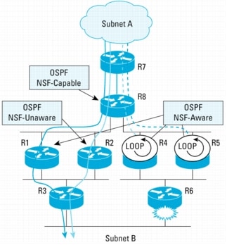
Traffic Flow When an OSPF NSF-Unaware Neighbor Is Present
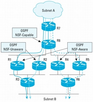
In Figure 8, R8 is the NSF restarting router. Four of its neighbors (R1, R4, R5, and R7) are NSF-aware routers. R2 is NSF-Unaware. This is designed purposefully, because it illustrates the outcome of traffic flows when an NSF-unaware router is present. It is also assumed that all links have an equal cost, and that the "enforce global" configuration option is not enabled. The "enforce global" option forces termination of all OSPF NSF procedures for all network segments if an NSF-unaware neighbor is detected.
Figure 8. OSPF NSF Example with NSF-Unaware Neighbor
Traffic Flow from Subnet-A to Subnet-B
• Before R8 RP switchover starts:
– R8 load balances the traffic flow to R1, R2, R4, and R5. The traffic flows are then sent to R3 and R6 to subnet B. This is illustrated in Figure 9.
• When R8 RP switchover occurs and NSF is in progress:
– R8 continues to forward traffic to the R1, R2, R4, and R5 just as in Figure 9.
Note: R2 is included even though it is not an NSF-aware router, because the FIB on the line card of the restarting router remains intact during the switchover time, regardless of whether its neighbor is NSF-aware.
• After R8 switchover has completed:
– The traffic flows continue to follow the same paths as illustrated in Figure 9 as they did prior to the switchover.
Figure 9. Traffic Flow from Subnet A to B Before Switchover
Figure 10. Traffic Flow from Subnet B to subnet A Before Switchover
Traffic Flows from Subnet B to Subnet A
• Before R8 RP switchover starts:
– Assume the traffic from subnet B is sent to both R3 and R6. R3 load balances traffic destined for subnet A over R1 and R2. Similarly, R6 load balances the traffic destined for subnet A it receives over R4 and R5. The traffic flow before switchover is illustrated in Figure 10.
• When R8 RP switchover occurs and NSF is in progress:
– The traffic flows only to R6 and then is load balanced through R4 and R5 as depicted in Figure 11.
– The flows are not going across the Rtr1 and Rtr2 paths. This is because R2 is not NSF-Aware. Because of this, R8 terminates the NSF procedures on the segment connecting R1 to R2.
– This will cause the OSPF adjacencies between R8 and R1 and R2 to flap. R1 and R2 floods LSAs to R3 to update the topology. The routes through R8 are removed on R1, R2, and R3 as a result, leaving only the paths known to R6.
– Here we assume the traffic from subnet B will be directed to R6. The traffic from subnet B destined for subnet A flows only over the right side of the network as shown in Figure 11.
• After Rtr8 switchover has completed:
– The traffic flows return back to their original paths (as they were prior to the switchover), as shown in Figure 9 and Figure 10.
Figure 11. Traffic Routed Around R1 and R2 Because R2 Is Not NSF-Aware
Traffic Flow When a Topology Change Occurs During NSF Process
It should be rare that a topology change occurs while the NSF procedures are in progress. Under this circumstance, the NSF process would continue. This section discusses how traffic might be affected when NSF procedures are in progress and a topology change occurs concurrently. We will use the same example network topology in the previous figures but now consider R2 to be NSF-Aware.
The diagram in Figure 12 shows the traffic flow while NSF procedures are in progress because of a switchover at R8.
Figure 12. Traffic Flow Before and During Switchover
Now assume the link on R6 fails, causing a topology change to occur. When this happens, R6 generates LSAs and floods them to its OSPF area.
When R4 and R5 have received the LSAs, they know that the path to subnet B through R6 no longer exists. R4 and R5 recalculate the path and figure out that the subnet B can be reached through R8. Thus, they pick up R8 as the next hop to reach subnet B. This creates a temporary routing loop, as illustrated in Figure 13.
The duration whereby this routing loop exists will be short. NSF procedures are still in progress, and when the OOB-Resync procedures are completed between R8 and R4 or R5, R8 will know that the path to subnet B through R6 is no longer available which breaks the routing loop.
Note: The routing loop will not always occur when there is a topology change during the NSF process. It depends on the network topology, the type of the change (that is, flapping of a stub network will not cause a routing loop), and the timing of the change.
An alternative is to terminate NSF when a change in topology occurs while NSF procedures are in effect. Termination of the NSF process during a topology change eliminates all the benefits of Cisco NSF. Consider that if NSF is terminated during the topology change, none of the four flows will reach the subnet B. In other words, the traffic would be black-holed. Even without the implementation of NSF/SSO, traffic loss is a common occurrence because of an RP switchover until network reconvergence is complete. Considering all sides, the benefits of NSF/SSO outweigh the consequences.
Figure 13. Temporary Loop Due to Routing Change During NSF Procedures
OSPF NSF Configuration
To configure NSF operations for OSPF, use the nsf command in router configuration OSPF mode:
router(config)# router ospf 100
router(config-router)# nsf
Note: You do not have to configure a router to be NSF-aware. A router running a Cisco IOS Software Release that is capable of supporting NSF procedures will exhibit NSF awareness without any configuration.
To optionally terminate the OSPF NSF process for the entire router when detecting an OSPF NSF-unaware router, configure the "enforce global" keywords.
router(config)# router ospf 1
router(config-router)# nsf enforce global
IS-IS NSF
The objective of IS-IS NSF is to perform a graceful restart when RP switchover occurs. The graceful restart must occur in such a way that the impact on routing is minimized and packet forwarding is not disrupted.
IS-IS, like OSPF, is a link state routing protocol. Therefore, all routers in the same routing area must maintain a consistent view of routing topology. For example, if there is a change in the routing topology, then Link State Protocol data units (LSPs) are flooded out to the entire IS-IS area. As a result, all routers in that area execute the SPF algorithm, update the RIB, and repopulate the FIB.
The network can be unstable during reconvergence, thus imparting negative side effects affecting packet delivery. RP switchover can be viewed as a recovery procedure rather than a change in routing topology. After switchover the routing topology will have resumed its previous status. The routing instability can be avoided if the restarting router can relearn or preserve the routing information without causing LSP flooding and neighbor adjacency flap.
Like with OSPF, there are two main challenges that the IS-IS routing protocol needs to address to achieve this goal:
• Maintain neighbor adjacency and avoid unnecessary LSP flooding when switchover occurs.
• Resynchronize link state database (LSDB) for the new active RP with its adjacent neighbors.
There are two solutions to address this problem. One is a stateful routing solution that is Cisco specific and the other is much like the previously described methods used for OSPF and BGP. The Cisco IOS Software-specific solution uses checkpoint facilities to back up the states of the IS-IS adjacencies and database on the standby RP. The second solution is based on IETF work and uses a new TLV in the IS-IS Hello PDU. Consequently, the second method requires a supportive neighbor to work.
Cisco Stateful Solution
Using the Cisco stateful routing solution, full adjacency and LSP information is saved, or "checkpointed", to the Standby RP. Following a switchover, the newly active RP maintains its adjacencies using the checkpointed data, and can quickly rebuild its routing tables.
This Cisco specific solution addresses the two aforementioned problems (adjacency reacquisition and LSDB resynchronization) in an innovative and unique way.
Maintaining Adjacencies
According to IS-IS protocol, adjacencies are maintained by the periodic transmission of Hello messages. If an intermediate system (IS) fails to receive a Hello for the adjacency holding time, then the adjacency is dropped. Adjacencies are also reinitialized if the Hello does not contain the appropriate state information (that is, if it does not list the system ID (for point-to-point links) or MAC address (for LAN segments) of the receiving IS in the Hello). Consequently, an NSF mechanism must restart quickly enough that neighbors do not drop their adjacencies because of timeouts. Secondly, the NSF process must maintain state so that Hellos have the appropriate information to prevent neighbors from noticing the restart.
The Cisco solution overcomes these challenges and prevents the neighbor from cycling the adjacency by checkpointing the appropriate state information and using it after restart. Mechanisms were designed for both point-to-point adjacencies and LAN adjacencies.
LSP Database Synchronization
Database synchronization is another subset of the reinitialization process. The IS-IS protocol allows for a mechanism to synchronize link state databases with neighboring routers. Under normal circumstances, a reboot would trigger adjacency reinitialization and subsequent LSP database synchronization. Because adjacency reinitialization will be suppressed with the Cisco IS-IS stateful solution, a specific mechanism is used to synchronize the router LSP database without triggering a topology change.
Again, mechanisms were developed to handle point-to-point interfaces and LAN interfaces.
IETF Solution
The IETF solution defines a mechanism whereby a restarting router can signal its neighbors that it is restarting and allow them to reestablish their adjacencies without cycling through the down state while still correctly initiating database synchronization. Unlike the Cisco stateful IS-IS routing solution described previously, the IETF solution is stateless. It does not checkpoint the content of the LSP database and the adjacency information.
The IETF solution does not hide the fact that the restarting router has restarted. The restarting router indicates clearly that it has restarted and makes sure that it acquires the content of the LSP database from its neighbors. The neighbors are aware of this fact, and cooperate with the restarting router.
Adjacency Reacquisition
Adjacency reacquisition is the first step in reinitialization. The restarting router explicitly notifies its neighbor that the adjacency is being reacquired, and hence that it should not reinitialize the adjacency. This is achieved by the inclusion of a new "restart" option (TLV) in the Hello PDU. The presence of this TLV indicates that the sender supports the new restart capability, and it carries flags that are used to convey information during a restart. All Hello messages transmitted by a router that supports this capability include this TLV. This TLV contains two flags: RR to indicate a "Restart Request" and RA to transmit a "Restart Acknowledgement"; and a "Remaining Time," which informs the restarting router the allowable duration for its recovery.
Neighboring routers of a restarting router, on receipt of a Hello message with the "restart" TLV having the RR bit set, leaves the adjacency with the restarting router in "Up" state and sends a Hello message, including the RA bit set, to acknowledge this restart.
Multiple Levels
A router that is operating as both Level 1 and Level 2 on a particular interface performs the above operations for each level:
• LAN interface: The router sends and receives both Level 1 and Level 2 Hellos and performs the Complete Sequence Number PDU (CSNP) synchronizations independently for each level.
• Point-to-Point interface: Only a single Hello message (indicating support for both levels) is required, but the CSNP synchronizations are performed independently for each level.
LSP Database Synchronization
When a router restarts, it can expect to receive CSNP(s) that reflect the LSP state held by each neighbor over each interface. The arrival of the CSNP(s) is now guaranteed, because the "restart" Hello with the RR bit set will be retransmitted until the CSNP(s) are correctly received. Synchronization will be complete when all these LSPs have been received.
LSP Generation and Flooding
After all adjacencies have been reinitialized, the router assumes that all available adjacency information has been reacquired and IS-IS can now generate its own LSP. To achieve a localized restart, it is important that the LSP of this router not be generated and propagated before sufficient information is acquired to reflect the state of the router prior to the restart. It is also likely that an old copy of the LSP of the local router will be received prior to the local LSP regeneration phase.
Under normal conditions, LSP copies that are received from a router that is no longer generating should be purged. However, in the case of a restarting router, it is possible to receive a new LSP that does not need to be generated (that is, Level 1 SPF has been run and prefixes that should be propagated into Level 2 were discovered). Purging the "extra" LSP would now rip out all the other routers and disrupt their FIBs. Instead, an NSF-aware router ignores this "extra" LSP until all the redistributions between protocols and IS-IS levels are performed. The "extra" LSPs are purged after the synchronization point is reached.
Similarly, redistribution of inter-level information is regenerated before the LSP of this router should be flooded to other nodes. Sending out Level 1 or Level 2 LSP is delayed until the SPF of the other level has been run and it can be determined that any inter-level information that must be propagated has been included in this LSP.
Note: Information that has not been added into the RIB during a "first iteration" SPF should not result in dropped traffic to these destinations, because the FIB maintains these entries. Redistribution of routing protocol information other than IS-IS may be dependent upon the appropriate routing information being updated in the RIB prior to the final NSF IS-IS LSP generation.
SPF Computation
After the LSP database has been resynchronized, the link state database is now current. SPF computation is run to propagate all reinitialized information to the RIB and FIB. Any routes that have not been refreshed by this process are aged and then purged after a hold time period to limit black holing and routing loops.
IS-IS NSF Protocol Extension Procedures
This section will describe the IS-IS NSF for the IETF implementation.
Cisco IETF Implementation of ISIS NSF
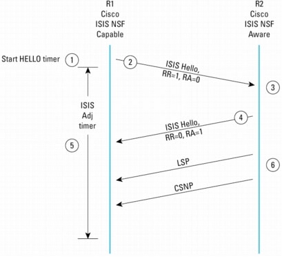
This next sequence describes the IS-IS procedures according to the IETF implementation. Refer to the diagram in Figure 14.
1. R1 restarts.
2. R1 sends a Hello message including TLV 211 with RR bit set and RA bit cleared indicating that it has restarted.
3. R2 receives R1's Hello message.
4. R2, because it is IS-IS NSF-aware, responds with a Hello message including TLV 211 with RR bit cleared and RA bit set: R2 indicates that it acknowledges the previous Hello received from R1.
5. R1 receives Hello message from R2.
6. If the interface is a Point-to-Point interface, or if R2 has the highest router priority (with highest source MAC address breaking ties) among those routers whose IS-IS Hellos (IIHs) contain the restart TLV (excluding R1), R2 sends a complete set of CSNPs. When both this CSNP and the above Hello message sent in 4 are received, the Adjacency timer is cancelled. If the adjacency timer expires, R1 resends the Hello message with RR bit set.
Figure 14. IS-IS NSF Procedures for the IETF Implementation
Example with an IS-IS NSF-Unaware Peer
The description below follows the case where the IETF IS-IS NSF capability is enabled but a peer router is not NSF-aware. Refer to the diagram in Figure 15.
7. R1 restarts.
8. R1 sends a Hello message including TLV 211 with RR bit set and RA bit cleared indicating that it has restarted.
9. R2 receives Hello message from R1.
10. R2, because it is NOT NSF-aware, responds with a Hello message without TLV 211. The adjacency is dropped.
11. R1 receives the Hello message without TLV 211, reinitializing the adjacency with R2. R1 sends a Hello message with TLV 211 but RR and RA bits are cleared. The purpose is not necessarily to reinitialize the adjacency (because R2 has already done this), but to do the "normal" adjacency acquisition process.
Note: An IETF IS-IS NSF-capable router will disable NSF processing on all other segments if an NSF-unaware router is detected.
Figure 15. IETF IS-IS NSF Procedures with an IS-IS NSF-Unaware Peer
IS-IS NSF Deployment
The recommended target deployment point for IS-IS NSF is on:
• Routers that are represented as a single point of failure
• Routers that would cause undesired network instabilities if RP switchover occurs
Cisco IS-IS NSF offers the benefit to work at the same level of efficiency regardless of the NSF router neighbor capabilities. Neighbors of IS-IS NSF-enabled routers should be NSF-aware if the IETF version is deployed, because IS-IS NSF procedures involve both a restarting router and its neighbors.
Timer Tuning Consideration
A typical time-out period for dropping adjacencies is thirty seconds on a Point-to-Point link and ten seconds on a LAN. If the transmission of Hellos can be resumed before this period expires, the neighbor will not drop its adjacency. This suggests that hold times for Hellos should be configured large enough to permit a process restart before adjacencies expire.
Note that this pits the goal of "smooth" restart against the goal of reacting quickly to link (and subsequent topology) changes. However, configuring a larger hold time is not sufficient to ensure smooth restart. If Hello timers are jittered, the Hellos and hold-time expirations will be uniformly distributed over the hold interval. This means that at any given moment, a large number of adjacencies are on the verge of expiring. The only reasonable way to prevent the loss of all the nearly expired adjacencies is to assure that the hello multiplier is greater than 1. This is common practice, but is an absolute requirement for NSF. Having a Hello multiplier of 2 or 3 assures that (at least for adjacencies for which Hellos have not been lost) the restarting process has a full Hello interval in which to recover. When the number of interfaces is high, it is necessary to determine the IS-IS restart times for an NSF router.
IS-IS NSF Configuration
To configure NSF operations for IS-IS, use the nsf command in router configuration IS-IS mode. By default, NSF restarting is off but the router includes the IETF TLVs by default. The mode of operation (Cisco or IETF) is chosen at this stage.
router(config)# router isis
router(config-router)# nsf [cisco/ietf]
The following command limits the interval (in a 0-1440 minutes range) between two restarts. If the router's Active and Standby RPs have not remained up for at least this time, ISIS NSF is canceled. The default value is 5 minutes.
router(config)# router isis
router(config-router)# nsf interval 600
The following command sets the time (in a 1-60 seconds range) an NSF restart will wait for all interfaces with IS-IS adjacencies to come up before completing the restart. The default value is 10 seconds.
router(config)# router isis
router(config-router)# nsf interface wait 20
In IETF mode and only in this mode, the following command sets the time (in seconds) NSF will wait for the LSP database to synchronize before generating and flooding its own LSP with the overload-bit set.
router(config)# router isis
router(config-router)# nsf t3 manual 60
If the "adjacency" keyword is used, this above-mentioned t3 time would be determined from the adjacency hold time advertised to neighbors prior to switchover.
router(config)# router isis
router(config-router)# nsf t3 adjacency
EIGRP NSF
Enhanced Interior Gateway Routing Protocol (EIGRP) is an interior gateway protocol suited for many different topologies and media. EIGRP is an enhanced distance vector routing protocol, relying on the Diffused Update Algorithm (DUAL) to calculate the shortest path to a destination within a network. In a well-designed network, EIGRP scales well and provides extremely quick convergence times and minimal overhead traffic. Like the routing protocols described thus far, the goal for the interaction of EIGRP routing protocol with NSF is to perform a graceful restart when an RP switchover occurs such that the impact on routing is minimized, and packet forwarding is not disrupted.
Maintaining Neighbor Adjacency
As with other protocols, for NSF to occur, the peer to the restarting router must continue to forward packets to the restarting router during the switchover. The peer, therefore, must not reset the neighbor adjacency.
To prevent the adjacency reset by the neighbors, the restarting router notifies peers of its intent to provide service during a switchover by setting a new Restart (RS) bit in the EIGRP packet header to indicate a restart. When EIGRP NSF is configured, the RS bit is set in the hello packets and the initial INIT update packets sent during the NSF restart period. By setting the RS bit in the hello packets, the restarting router is able to quickly notify the neighbors of the switchover. This also allows the NSF aware peer to know that it should follow the NSF extensions rather than use the normal adjacency discovery and startup method.
A non-NSF-aware neighbor will ignore the new RS bit. It will reset the adjacency when it receives the INIT update packet or if the hold timer expires.
Upon receiving the restart indication, either by receiving the hello packet or the init packet, the neighbor will make a note of the restarting peer in its peer list, and will maintain the adjacency with the restarting router. The neighbor router does not communicate any state change about the restarting router to any of its own neighbors, but instead, marks routes through the restarting router as stale and continues to forward packets to the restarting router. This avoids the detrimental effects on network performance associated with the failure of a router.
EIGRP NSF Protocol Extension Procedures
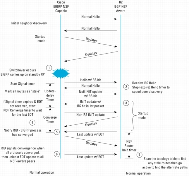
Figure 16 depicts the protocol exchange between an NSF-capable EIGRP router and an NSF-aware EIGRP peer when the NSF-capable router undergoes a switchover.
When the adjacency is first formed, the RS bit is not used. It is therefore not possible to determine in advance through CLI commands if a peer is capable of supporting the EIGRP NSF procedures. You must have access to each router or know the Cisco IOS Software version to determine its support for EIGRP NSF.
1. When a switchover happens and the standby RP becomes active, EIGRP will initiate Hellos with the RS bit set. This is the indication to peers that a restart has occurred.
2. Here the peer is EIGRP NSF-aware and therefore recognizes the RS bit and retains its forwarding state with regard to the restarting router. In other words, it does not reset the adjacency but continues to forward packets through the restarting router as if nothing happened.
The NSF-aware router may receive the Hello packet before the INIT packet when the restarting router has not yet rediscovered the peer. To speed up the peer rediscovery process for the restarting router, the NSF aware router sends Hello packets back immediately, and at a shorter Hello time interval.
3. The NSF-aware neighbor then sends its topology table to the restarting router with the RS bit set in the first update packet, indicating that it is NSF-aware and is helping out the restarting router. The NSF-aware neighbor does not set the RS bit in its hello packets because it did not undergo a switchover or a restart.
Note: A router maybe NSF-aware but still not be executing the restart procedures. This would occur when the restarting neighbor has been reloaded and is coming up from a cold start.
Figure 16. EIGRP NSF Procedures
4. The restarting router and the peer(s) exchange routing updates and the NSF-capable router rebuilds its database. The restarting router knows the process is complete when it has received the End-of-Table (EOT) marker in the topology table update. Each NSF-aware router is required to send an End-of-Table marker in the last update packet to indicate the end of the table content.
In addition to the End-of-Table marker method, EIGRP uses a timer (called the nsf converge timer) to set an upper bound for how long to wait for all End-of-Table markers to be received.
5. The restarting router sends updates as normal and signals the RIB as soon as it has received EOT indication from all its peers. When the restarting router has received all EOT indications from its neighbors or when the NSF converge timer expires, EIGRP performs a Diffusing Update Algorithm (DUAL) calculation to select the best loop-free routes for each destination in the topology database, and notifies the RIB of convergence.
6. Sometime later, when the RIB has received the convergence signal from all the protocols, it would notify EIGRP of RIB convergence. When the RIB is converged, the restarting router sends an EOT update to the NSF-aware peers that have been participating in the restart. This EOT update sent by the restarting router following notification of RIB convergence has only the EOT flag set in the packet header and contains no topology information.
7. A NSF-aware peer would know when the restarting neighbor converged when it receives an EOT indication from the restarting router. The peer then scans its topology table to search for the routes with the restarted neighbor as the source. It compares the route timestamp with the restart event timestamp to determine if the route is still available. The peer then goes active to find alternate paths for any routes that are no longer available through the restarted router.
At this point all NSF extensions have been completed and normal EIGRP processing continues.
EIGRP NSF Deployment
For the restarting router to perform NSF properly, the peer routers must also run a Cisco IOS Software version with the EIGRP NSF feature. If a peer router is running a Cisco IOS Software version without EIGRP NSF, the result of a switchover should be no worse than an adjacency reset. This is because the non-NSF EIGRP router would reset the adjacency when it receives the INIT update packet from the restarting router.
This EIGRP NSF design does not support the case where two neighboring routers undergo a switchover or NSF restart at the same time. If both routers restart concurrently, one will be signaled of the other's restart by the RS bit in the Hello packets or the INIT update packet. Both routers will go through the normal non-NSF restart and their peer relationship will be reestablished using the non-NSF method.
Three new timers to be aware of that have been added with EIGRP NSF:
• Signal timer-Each EIGRP process starts a signal timer when it is notified of a switchover event. Hellos with the RS bit set will be sent during this period.
• Converge timer-The Converge timer may be used to wait for the last EOT update if all startup updates have not been received within the signal timer period. If an EIGRP process discovers no neighbor, or if it has received all startup updates from its neighbor within the signal timer period, the Converge timer will not be started.
• Route-Hold timer-A NSF-aware peer will start the Route-Hold timer to wait for the EOT from the restarting router. At the end of this timer period, the peer will stop waiting, start scanning the topology table, and go active on those routes that were not updated by the restarting router. The Route-Hold timer may be tuned (shortened) so the peer can find alternate paths faster and avoid black holing traffic if the restart period is too long.
EIGRP NSF Configuration
EIGRP NSF is disabled by default. The user command to enable or disable NSF is:
router eigrp <AS-number>
[no] nsf
Timers may be specified using the commands:
router eigrp <AS-number>
[no] timers nsf signal <seconds>
[no] timers nsf converge <seconds>
[no] timers nsf route-hold <seconds>
High Availability for MPLS Networks
Cisco IOS Software Release 12.2(25)S introduces HA for the MPLS environment. Support for MPLS High Availability is targeted mainly toward the Service Provider Edge (PE) devices that provide access to the MPLS network. These devices often represent single points of failure for customers of MPLS VPN services in the same way as edge routers in a pure IP network that is not based on an MPLS core.
At the time this document was prepared, support for the MPLS High Availability (MPLS-HA) feature had been released for the Cisco 7500 Series Routers only. Other products will support MPLS HA over time. MPLS HA for the Cisco 7500 Series products enabled support for NSF/SSO for MPLS Layer 3 VPNs and LDP NSF or Graceful Restart. As with other protocols discussed earlier, the LDP implementation requires LDP Graceful Restart (NSF awareness) at the adjacent peer router. LDP GR awareness is available for the Cisco 12000 Series products in Cisco IOS Software Release 12.0(29)S and above.
Networks running Cisco IOS Software that does not yet offer complete support for MPLS will still see packet loss for MPLS traffic during an RP switchover. However, some benefit is still seen by enabling NSF/SSO even in this case because of the faster recovery that occurs from the link layer state being maintained by SSO. Testing has shown that for many link types, when a switchover occurs on a router with a MPLS interface, the traffic loss was measured to be the about the same as if the router had experienced a RPR+ switchover. Some link types, however, will show an improvement. Although the LDP process must fully restart and learn labels before forwarding can continue, the speed of the restart is improved by enabling NSF/SSO.
As MPLS-HA becomes available for the Cisco 12000 Series products and others, the same zero packet loss will become possible for MPLS Layer 3 VPNs and later for MPLS Layer 2 VPNs.
MPLS HA Features
With Cisco IOS Software Release 12.2(25), the following MPLS features now have the ability to continue forwarding data following a route processor (RP) switchover:
• MPLS Virtual Private Networks (VPNs): This allows a router to recover from a disruption in service without losing its VPN prefix information by utilizing the BGP NSF Graceful Restart mechanisms. BGP Graceful Restart now supports the VPNv4 VRFs, allowing the routers running BGP Graceful Restart to preserve VPN prefix information when a router restarts.
• MPLS Label Distribution Protocol (LDP): MPLS LDP uses SSO, and NSF or Graceful Restart to allow an RP to recover from disruption in the LDP components of the control plane service without losing its MPLS forwarding state. LDP Graceful Restart works with LDP sessions between directly connected peers as well as with peers that are not directly connected (targeted sessions).
• Any Transport over MPLS (AToM): AToM uses SSO, NSF, and Graceful Restart to allow an RP to recover from disruption in the LDP components of the control plane service without losing its MPLS forwarding state.
• Also included is SSO support for the MPLS VPN MIB, the MPLS LDP MIB with the IETF Version 8 Upgrade.
MPLS-HA Coexistence Features
At the time this paper was prepared, the following MPLS features had not been enabled for HA and therefore do not maintain state information following a switchover but do coexist with NSF/SSO and MPLS-HA:
• MPLS Traffic Engineering
• MPLS Quality of Service Applications
• IPv6 over MPLS
• IPv6 over MPLS
• MPLS Label Switching Router MIB
• MPLS TE MIB
• MPLS Enhancements to Interfaces MIB
For more details, please see the references section at the end of this document.
MPLS HA Prerequisites
MPLS HA relies on the underlying NSF/SSO features we have been discussing so far for operation. The prerequisites are summarized below:
• BGP NSF mechanisms must be enabled. BGP Graceful Restart allows a router to create MPLS forwarding entries for VPNv4 prefixes in NSF mode. The forwarding entries are preserved during a restart. BGP also saves prefix and corresponding label information and recovers the information after a restart.
• NSF support for the label distribution protocol in the core network
• NSF support for the Internal Gateway Protocol (IGP) used in the core; that is, OSPF or IS-IS
• NSF support for the routing protocols between the PE and Customer Edge (CE) routers
MPLS-HA Operation
When BGP allocates local labels for prefixes, it checkpoints the local label binding in the backup route processor. The check pointing function copies state information from the active route processor to the backup route processor, thereby ensuring that the backup route processor has an identical copy of the latest information. If the active route processor fails, the backup route processor can take over with no interruption in service. Check pointing begins when the active route processor does a bulk synchronization, which copies all the local label bindings to the backup route processor. After that, the active route processor dynamically checkpoints individual prefix label bindings when a label is allocated or freed. This allows forwarding of labeled packets to continue before BGP reconverges.
When a router that is capable of BGP Graceful Restart loses connectivity, the following happens to the restarting router:
1. The router establishes BGP sessions with other routers and relearns the BGP routes from other routers that are also capable of Graceful Restart. The restarting router waits to receive updates from the neighboring routers. When the neighboring routers send end-of-Routing Information Base (RIB) markers to indicate that they are done sending updates, the restarting router starts sending its own updates.
2. The restarting router accesses the checkpoint database to find the label that was assigned for each prefix. If it finds the label, it advertises it to the neighboring router. If it does not find the label, it allocates a new label and advertises it.
3. The restarting router removes any stale prefixes after a timer for stale entries expires.
When a peer router that is capable of BGP Graceful Restart encounters a restarting router, it does the following:
1. The peer router sends all the routing updates to the restarting router. When it has finished sending updates, the peer router sends an end-of-RIB marker to the restarting router.
2. The peer router does not immediately remove the BGP routes learned from the restarting router from its BGP routing table. As it learns the prefixes from the restarting router, the peer refreshes the stale routes if the new prefix and label information matches the old information.
If a router is not configured for VPN NSF and it attempts to establish a BGP session with a router that is configured with VPN NSF, the two routers create a normal BGP session but do not have the ability to perform VPN NSF.
LDP Graceful Restart (NSF)
LDP NSF or LDP Graceful Restart (GR) is a mechanism that can be used by two Label Switch Routers (LSRs) to protect LDP and forwarding state when LDP communication between them is lost and later restored as in the case of an RP switchover at one of the LSRs. LDP GR enables non-stop MPLS forwarding for traffic that uses labels previously learned by the interrupted LDP communication during the communication failure and recovery.
The implementation protects against a restart of the LDP component (control plane) as well as from the momentary interruption of LDP communication with a neighbor. A restart of the LDP component (LDP restart) causes an interruption of LDP communication with all LDP neighbors and results in a loss of the LDP state learned from those neighbors. If the LDP component does not restart but merely loses communication with a neighbor (LDP session reset), then the LDP state learned from that neighbor may be retained, including any associated forwarding state.
LDP GR operates in a manner similar to other NSF protocols described in this document. LDP GR requires that an LSR perform the following actions in order to recover from the failure of LDP communication:
• When a failure of the LDP communication is detected, mark the associated forwarding state as stale, and retain it.
• Continue forwarding using the stale state.
• When the LDP communication is reestablished, recover and refresh the stale forwarding state.
• Remove stale forwarding state if it is not "refreshed" within a requested amount of time.
LDP GR Protocol Extension
Two Label Switching Routers (LSRs) that use LDP to exchange label mapping information are known as LDP peers. When one of the LDP peers is LDP GR-capable and the peer is at least LDP GR-Aware, MPLS HA is possible. LDP works by establishing an "LDP Session" between the peers along a label switching path. A single LDP session allows each peer to learn the other's label mappings.
Figure 17 depicts the LDP GR message flow between two LSRs.
LDP specifies that Hello messages are exchanged and that a TCP session be established to carry LDP messages.
1 & 2. An LSR indicates that it is capable of supporting LDP Graceful Restart by including the Fault Tolerant (FT) session TLV as an optional parameter in the LDP Initialization message. The L (Learn from Network) flag indicates that the LDP GR procedures are used. The optional FT Session TLV has been defined in a manner that allows backwards compatibility. The TLV 'U bit' will cause the recipient to silently discard the TLV if it does not support LDP GR. In that situation, the LDP session will be established, but GR will not be attempted.
There are two timer fields associated with LDP GR and present in the FT Session TLV:
• Reconnect Timeout: the time (sent in milliseconds) that the sender of the TLV would like the receiver of that TLV to wait after the receiver detects the failure of LDP communication with the sender. While waiting, the receiver retains the MPLS forwarding state for the (already established) LSPs that traverse a link between the sender and the receiver. The FT Reconnect Timeout should be long enough to allow the restart of the control plane of the sender of the TLV, and specifically its LDP component to bring it to the state where the sender could exchange LDP messages with its neighbors. The default value for this timer is 120 seconds.
Setting the FT Reconnect Timeout to 0 indicates that the sender of the TLV will not preserve its forwarding state across the restart, yet the sender supports the procedures, as defined in Section 3.3, "Restart of LDP communication with a neighbor LSR" of RFC 3478.
• Recovery Time: For a restarting LSR, the Recovery Time carries the time (sent in milliseconds) the LSR is willing to retain its MPLS forwarding state that it preserved across the restart. The time is from the moment the LSR sends the Initialization message that carries the FT Session TLV after restart.
Figure 17. LDP Graceful Restart Extensions
Setting this time to 0 indicates that the MPLS forwarding state was not preserved across the restart.
3. Exchange of label information prior to a restart.
4. When a RP hardware or software failure triggers a switchover, the restarting LDP component of the router will establish a new TCP session to its peer(s). The LDP GR-capable router starts an internal timer, called MPLS Forwarding State Holding timer (forwarding-holding), and marks all the MPLS forwarding state entries as "stale". The router is said to be in LDP restart mode. The default value for the forwarding-holding timer is 600 seconds.
5. R2, the LDP GR aware peer, upon detection of the failure and the restart, initializes a timer called the liveness timer. This timer indicates the amount of time the peer LSR keeps its stale label-FEC bindings. It is set to the lesser of the FT Reconnect Timeout, as was advertised previously by the restarting router, and a local timer, called the Neighbor Liveness Timer.
If within this time the LSR still does not establish an LDP session with the neighbor, all the stale bindings are deleted.
6. The restarting LSR sets the Recovery Time sent in the FT Session TLV to the current value of the MPLS Forwarding State Holding timer. The timer indicates how much longer the preserved forwarding state will be kept.
7. The LDP session is established. If an LDP session is reestablished with the neighbor before the reconnect timer expires, the reconnect timer should be stopped, and the recovery timer is started.
8. LSRs exchange address prefix/label messages.
9. One more timer (max-recovery) is used by the LDP component to remove any stale outgoing label bindings that have not been re-advertised by the peer routers. The timer is started when the Initialization message is sent. The default is 120 seconds. When the timer expires, LDP removes all outgoing label bindings in the LIB that are marked as stale and were learned from the restarting neighbor associated with the timer expiry. Label binding removal triggers the removal of any associated forwarding state.
Peer Perspective
The LDP peer becomes aware of the LDP recovery in progress by means of some failure to the existing LDP session. LDP session failures are likely to be detected in the following cases:
• The last Hello adjacency for the session is lost.
• The KeepAlive timer for the session expires.
• The TCP layer announces that the connection has been lost.
• A normal close is triggered by the receipt of a Shutdown or Notification message.
The LDP GR-aware router is said to be in LDP session reset mode. The LDP GR-aware router starts a timer to establish the time for reestablishment of the LDP session with the restarting router. The amount of time a router waits for an LDP session to be reestablished is the lesser of either the Reconnect Time received from the peer in the Fault Tolerant (FT) Type Length Value (TLV) or the value of the neighbor-liveness timer. If the LDP session is established before the timer expires, the router deletes the stale label bindings associated with that neighbor. The default for neighbor liveness is 120 seconds.
Existing label bindings are used during the restart procedure. Outgoing label bindings will be advertised by the restarting router after the LDP session is reestablished. If LDP has retained a binding for an advertised prefix, then the new binding will be learned using existing LDP procedures. If a label binding has been retained, then LDP will clear the "stale" mark on the binding when the new binding is learned. If the same label has been advertised, then no further action is needed. If a new label has been advertised, then LDP must update the label binding using existing procedures for handling that event.
MPLS-HA Configuration
To enable support for MPLS-HA, the router capable of switching over to a redundant RP must first be in SSO mode. Then LDP Graceful Restart must be enabled. The IGP protocols and PE-CE protocols also must be enabled for NSF to gain the most benefit. An LDP peer must also be configured for LDP graceful restart. The specific configuration for LDP is described next.
LDP Graceful Restart Configuration
LDP GR is enabled by the following global command:
Router(config)# mpls ldp graceful-restart
LDP GR timer values may be specified using the related command:
With this command, the following timers may be specified:
• Forwarding-holding: Specifies the amount of time the MPLS forwarding state should be preserved after the control plane restarts.
• Neighbor-liveness: Specifies the amount of time a router should wait for an LDP session to be reestablished.
• Max-recovery: Specifies the amount of time a router should hold stale label-FEC bindings after an LDP session has been reestablished.
You can determine the status of LDP graceful restart using the command:
router#sh mpls ldp gr
LDP Graceful Restart is enabled
Neighbor Liveness Timer: 120 seconds
Max Recovery Time: 120 seconds
Forwarding State Holding Time: 600 seconds
Down Neighbor Database (0 records):
Graceful Restart-enabled Sessions:
VRF default:
Peer LDP Ident: 88.1.11.1:0, State: estab
NSF/SSO SOFTWARE AND HARDWARE SUPPORT
Support for Cisco Nonstop Forwarding with Stateful Switchover first appeared in Cisco IOS Software 12.0(22)S. Support for NSF/SSO has expanded to other releases and includes support for MPLS-HA in Cisco IOS Software Release 12.2(25)S for the Cisco 7500 Series routers. NSF/SSO is now available for a wide range of Cisco products, route processors, and line card hardware. NSF awareness is also prevalent in several releases for multiple Cisco product families.
Hardware Restrictions
The router must have compatible RPs and line card equipment installed to support SSO. In addition, care should be taken when mixing RP types:
• Cisco 12000 Series Internet Router: GRP and GRP-B RPs can be used together. If using a PRP on this router, it must be paired with another PRP.
• Cisco 10000 Series Internet Router: Two PRE-1s or PRE-2s must be used. The original PRE for this router does not support Cisco NSF with SSO. MPLS-HA will be supported in Cisco IOS Software Release 12.2S for the PRE-2.
• Cisco 7500: RSP-2 and RSP-4 can be used in combination. RSP-8 and RSP-16 can also be used in combination. However, an RSP-8 or RSP-16 cannot be mixed with an RSP-2 or an RSP-4.
• For the Cisco Catalyst 6500 Series and Cisco 7600 Series, Supervisor Engine 2 and Supervisor Engine 720 are supported. Like Supervisors must be used.
• Certain products may display a warning if the physical characteristics of the RP hardware differ (for example, differing memory capacity). The system may progress to SSO mode if the differences are allowed. Network designers should verify that any physical differences will not impact performance in the event of a switchover.
A wide variety of line cards support Cisco NSF with SSO. For optimum performance, every card in the router chassis should support Cisco SSO. Check the latest Cisco documentation for the current list of supported line cards for each platform. If a particular line card is not supported by Cisco SSO, that specific line card will operate in RPR+ mode. At the time of the RP switchover, the distributed forwarding information on the card will be cleared. This will cause traffic loss to destinations reachable through that card in the event of a switchover. Other line cards will continue forwarding during the switchover.
Refer to appropriate documentation on CCO or see your Cisco representative for details about support for various Line Card or Module combinations.
NSF/SSO IMPLEMENTATION STEPS
This section provides an overview of the actual implementation steps that should be taken when deploying NSF/SSO.
Review Peering Combinations
The first step prior to implementation is to review your network and analyze the various peering combinations you have. Customers that have an all Cisco network will find deployment easiest. Those customers with multi-vendor environments will need to determine the level of support for graceful restart standards and protocol extensions. In either case, you may encounter various combinations of support for HA awareness.
Next formulate a strategy for implementation. A suggested method is to work out from the core. Bring higher tier, core-facing routers up to a level of Cisco IOS Software that supports the required NSF awareness. Then work site by site or at specific locations to implement NSF/SSO at the edge devices.
In the case where Route Reflectors are used, ensure these routers are BGP NSF-aware. When this is complete, you can begin to enable NSF/SSO at the network edge boundary.
Remember that although OSPF NSF awareness is on by default, BGP NSF awareness must be configured and the peer needs to be reset for BGP NSF to be enabled for that particular peer. Situations where OSPF NSF is enabled and BGP NSF is not are undesirable and should be avoided from an implementation standpoint.
Service Provider Deployment Example
Configuration Preparation
The first preparation step of deploying NSF/SSO within a Service Provider point of presence or site is to gather a list of all routers within the site by function. For example, customer access routers, aggregation layer routers, route reflectors, core routers, etc.
Double check that all routers are running the expected and appropriate level of software for deployment of NSF/SSO.
Peering configurations should again be verified for each router to ensure that all OSPF or IS-IS and BGP peers are accounted for when the actual configuration is performed.
A summary of the steps that might be taken in a particular network are as follows (this example assumes OSPF as the IGP and the use of Route Reflectors):
1. Configure BGP NSF on route reflectors so that they are NSF-aware.
2. Review the OSPF NSF capability of the core-facing routers.
3. Configure OSPF NSF and BGP NSF on the aggregation routers (resetting peers to RR can be done here, or after access routers are configured).
4. Configure OSPF NSF and BGP NSF on the customer access routers (edge routers).
5. Reset BGP peers so that all peers that are NSF-capable will negotiate the capability.
6. Configure all dual-RP routers for SSO.
7. Review customer NSF capability. If BGP is used between the SP edge and the customer network and code supports NSF, configure BGP NSF on customer router and reset the BGP session.
The detailed configuration commands to implement NSF/SSO are shown in the example below.
Step-by-Step Implementation Procedures
This section provides a sample deployment and the series of CLI configuration commands used to implement NSF/SSO.
It is worth mentioning a couple of operational notes particular to the Cisco 7500 and 12000 Series Routers.
Cisco 7500 Series Router Operational Notes
When a SSO switchover occurs, the new slave (old active) will remain in ROMMON for a period of 5 minutes before beginning its boot sequence. This is by design. The slave on the Cisco 7500 (unlike the Cisco 12000) cannot boot without the help of the master. The master provides a subset image over the bus to partially boot the RP. This 5-minute period is designed to allow the newly active RP time to do normal recovery activities while minimizing any impact from the processor-intensive task of loading the subset image on the slave.
When the slave does come back online, traffic may be interrupted a second time as the slave is reconnected to the bus. This traffic interrupt should be less than or equal to the original traffic loss upon switchover.
Cisco 12000 Series Router Operational Notes
Upon switchover, the new slave (old active) starts its boot process immediately. Because the processors can boot independently, there is no need to wait until the active processor is less busy.
No traffic loss occurs when the slave comes back online.
Configuration
The first configuration step is to enable BGP graceful restart for NSF awareness on all top-level route reflectors. The IGP must also be NSF-aware. OSPF awareness is on by default so no configuration is required. Note that the act of configuring BGP graceful restart on the route reflectors will have no effect on traffic. Use the following commands:
Router(config)#router bgp <as number>
Router(config-router)#bgp graceful-restart
Next, Enable OSPF NSF on the aggregation layer routers for this site (if relevant Cisco IOS Software-based devices exist)
Router(config)#router ospf <process id>
Router(config-router)#nsf
Use the same commands to enable BGP and OSPF graceful restart on all customer access layer or edge routers within the site:
Router(config)#router ospf <process id>
Router(config-router)#nsf
Router(config)#router bgp <as number>
Router(config-router)#bgp graceful-restart
At this point, the routers will be in one of the "undesirable" configuration states. OSPF NSF will be operational, but BGP NSF will not yet be operational, because the BGP peers have not yet been reset. Given the steps to configure NSF/SSO, this situation is unavoidable, so the next steps should be performed in a timely manner to ensure a full SSO/NSF operational state.
Next, the BGP peers will need to be reset. Typical Service Provider point-of-presence designs have redundant aggregation routers. In this case, it is easiest to issue clear ip bgp * on one aggregation layer router, wait for the peers to reestablish, then issue clear ip bgp * on the other aggregation layer router. This would catch all the BGP RR peers for the first site that was configured. As additional locations are configured, it is not necessary to once again reset the BGP RR peers to the sites that have already been reset using clear ip bgp *. Optionally, BGP peers can be reset individually, but it is important to ensure all BGP peers gain graceful restart capability.
Next, All aggregation and access layer routers that have dual processors should be configured for Redundancy Mode SSO.
For the Cisco 7500 Series Router, the hardware module commands need to be configured.
Note: The slots will vary based on whether the router is a Cisco 7507 or Cisco 7513
For both types of routers, use the following commands to configure SSO:
router#conf t
router(config)#redundancy
router(config-red)#mode sso
Configuring SSO will reset the slave automatically. No traffic loss will occur during the reset for the Cisco 12000 Series Routers. For Cisco 7500 Series Routers, the slave reset will cause traffic loss for a short duration when the slave comes back online.
Finally, the NSF/SSO configuration should be verified on each router.
For OSPF, the following command should reflect that NSF has been enabled:
router>sh ip ospf | inc Non-Stop
Non-Stop Forwarding enabled
For BGP, each peer should be viewed for the following line:
Graceful Restart Capability: advertised and received
The capability should be both advertised and received. If it is not received, then either the other end of the peer has not been configured for BGP Graceful restart, or the peer has not been reset.
Finally, the command sh redundancy should reflect that the router is running in SSO mode:
router>sh red
Redundant System Information:
------------------------------
Available system uptime = 12 minutes
Switchovers system experienced = 0
Standby failures = 0
Last switchover reason = none
Hardware Mode = Duplex
Configured Redundancy Mode = sso
Operating Redundancy Mode = sso
Maintenance Mode = Disabled
Communications = Up
SUMMARY AND BENEFITS
During the last few years, network availability has become an increasingly important topic for both Service Providers and Enterprises. Cisco has responded with a comprehensive strategy for high availability networking that includes Cisco IOS Software HA infrastructure and Cisco Nonstop Forwarding with Stateful Switchover and the various routing protocol extensions for graceful restart. As users and vendors gain more deployment experience with such enhancements, further refinements will be made to the protocols themselves and the way in which networks are deployed.
Cisco has implemented SSO as a Cisco IOS Software infrastructure capability. Cisco SSO actually provides capabilities beyond the maintenance of Layer 2 connectivity. It also manages state of all the supporting platform and infrastructure. Maintaining Layer 2 connectivity is simply the most outwardly visible of the services it provides.
In summary, Cisco continues to provide innovative features that address the needs of customers. The Cisco HA strategy is simple: To target all potential causes of downtime and offer features, function, best practice design recommendations, and operational procedures to increase MTBF and reduce MTTR. Cisco NSF/SSO is deployable today on existing hardware. It minimizes network routing protocol reconvergence and associated traffic bursts and CPU increases. And it will improve the measured availability of networks as well as the user perception of reliability.
RELATED STANDARDS AND DRAFTS
The mechanisms used to provide continuous forwarding in the event of a route processor switchover are not completely standardized. Relevant documents are listed below.
The Cisco implementation for BGP follows the specification described in draft-ietf-idr-restart-nn.txt. The latest version at the time of this writing was draft-ietf-idr-restart-10 and is a proposed standard.
The Cisco implementation for OSPF follows the specification described in the following IETF drafts:
• draft-nguyen-ospf-lls-04 2004-01-07 In IESG processing-see tracker
• draft-nguyen-ospf-oob-resync-04 2004-01-07 In IESG processing-see tracker
• draft-nguyen-ospf-restart-04 2004-01-07 In IESG processing-see tracker
The current standard for OSPF Hitless Restart is RFC 3623 Graceful OSPF Restart. The Cisco implementation is currently (at the time of this writing) not interoperable with RFC 3623.
The Cisco NSF implementation for IS-IS (IETF option) follows the specification described in RFC 3847 Restart Signaling for Intermediate System to Intermediate System (IS-IS) A Cisco specific stateful implementation is also supported and configurable.
The Cisco implementation for LDP follows the specification described in RFC 3478, Graceful Restart Mechanism for Label Distribution Protocol.
GLOSSARY
Autonomous System
Technically, a group of routers under a common administrative control. Practically, a group of routers that share a commonly configured autonomous system number in their BGP configuration.
Cisco Express Forwarding
Cisco Express Forwarding is a further optimization of the FIB, which allows very fast switching of IP packets. Distributed Cisco Express Forwarding is a variation of Cisco Express Forwarding that runs on line cards.
Convergence
The point at which every router on the network has received and processed all routing information from its peer routers.
eBGP
BGP peering connections between routers in different autonomous systems.
Forwarding Information Base
The Forwarding Information Base (FIB) is an optimized routing table formed by examining the RIB and selecting only the best paths to any particular IP destination. If load sharing or load balancing is enabled, multiple best paths may be selected.
iBGP
BGP peering connections between routers in the same autonomous system
Interior Gateway Protocol (IGP)
A protocol-typically OSPF, IS-IS or EIGRP-run within an autonomous system to provide next-hop reachability information.
Nonstop Forwarding
Cisco Nonstop Forwarding (NSF) refers to ability of a router to maintain forwarding state and reconverge routing protocols in the background during a route processor switchover. Because Cisco made extensions to BGP, OSPF and IS-IS, Cisco NSF is a handy term to collectively refer to those extensions.
NSF-capable router
A router that has implemented NSF, and will continue to forward packets after a RP failure. Note: Any NSF-capable router will also be NSF-aware. However, an NSF-aware router need not be NSF-capable.
NSF-aware router
A router that has implemented the necessary changes to the routing protocols to assist NSF-capable neighbors.
NSF-unaware router
Refers to a router that is not an NSF-aware restarting router - refers to a router that is experiencing RP switchover.
Routing Information Base
The aggregate collection of all routing information about a router. The Routing Information Base (RIB) may contain multiple references to different IP destinations.
Route Selection Process
The process by which Border Gateway Protocol (BGP) selects the best routes to particular destinations using all available information obtained from peers. Also known as best-path selection.
Stateful Switchover
Cisco Stateful Switchover (SSO) is the process by which information about platform, infrastructure and Layer 2 connectivity is shared between dual route processors. SSO also enables the maintenance of Layer 2 connectivity across a route processor switchover.