Change Node Configuration from BLSR to UPSR - Cisco ONS 15454
Available Languages
Contents
Introduction
This document describes how to convert from Bidirectional Line Switched Ring (BLSR) to Unidirectional Path Switched Ring (UPSR) through Cisco Transport controller (CTC) in a Cisco ONS 15454 environment.
Prerequisites
Requirements
Cisco recommends that you have knowledge of these topics:
-
Cisco ONS 15454
-
CTC
Components Used
The information in this document is based on these software and hardware versions:
-
Cisco ONS 15454 version 4.1.0, and later.
The information in this document was created from the devices in a specific lab environment. All of the devices used in this document started with a cleared (default) configuration. If your network is live, make sure that you understand the potential impact of any command.
Conventions
Refer to Cisco Technical Tips Conventions for more information on document conventions.
BLSR to UPSR Conversion
This document uses a lab setup with four nodes (Node1, Node2, Node3 and Node 4). Use these instructions to convert BLSR to UPSR.
Figure 1 – Topology 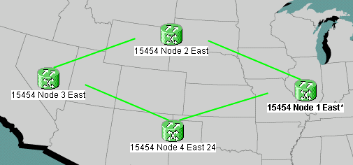
-
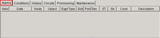
Verify whether the SONET Data Communications Channel (SDCC) works properly for all nodes. Examine the network view (figure 2) or the alarm (figure 3) on the CTC to ensure that there is no LOS on any of the optical span facilities.
Figure 2 – Network View on CTC
Figure 3 – Alarm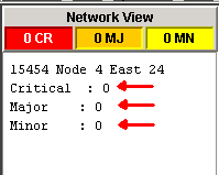
-
Perform a database backup on Node 1. Complete these steps:
-
Double-click Node 1. The node view for Node 1 appears.
-
Click the Maintenance > Database tabs.
Figure 4 – Backup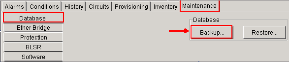
-
Click Backup. The Save dialog box appears.
Figure 5 – Save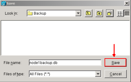
-
Save the database on the hard drive of the workstation, or on network storage. Use an appropriate file name with the .db file extension (for example, database.db).
-
Click Save.
-
Click OK in the confirmation dialog box.
Figure 6 – Backup Database - Confirmation Dialog Box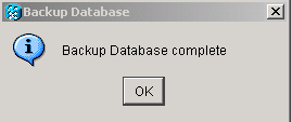
-
-
Repeat step 2 on Nodes 2, 3 and 4.
-
Export the circuit list. Complete these steps:
-
Double-click Node 1. The node view for Node 1 appears.
-
Click Export.
Figure 7 – Export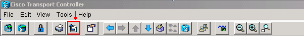
-
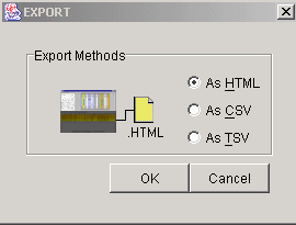
Select a data format in the Export dialog box (see figure 8).
-
As HTML—This saves data as a simple HTML table file without graphics. You must view or edit the file with applications like Netscape Navigator, Microsoft Internet Explorer, or other applications that can open HTML files.
-
As CSV—This saves the CTC table as comma-separated values (CSV).
-
As TSV—This saves the CTC table as tab-separated values (TSV).
-
-
Click the OK button.
-
Type a name in the File name field of the Save dialog box. Use one of these formats:
-
[filename].html—for HTML files
-
[filename].csv—for CSV files
-
[filename].tsv—for TSV files
-
-
Navigate to a directory where you want to store the file.
-
Click the OK button.
-
-
Repeat step 4 on Nodes 2, 3 and 4.
-
Verify the Maintenance tab to ensure that no ring switch operation is in progress. Check alarms and clear all alarms that are declared against all optical span card. You must clear all Timing synchronization and SDCC communication alarms on all nodes in a ring configuration before you move on to the next step.
-
Click the Provisioning > BLSR tabs, select the ring and click Delete.
Figure 9 – Delete BLSR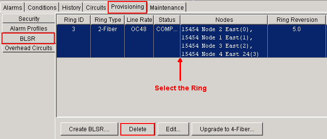
-
Click Yes in the Confirm Ring Deletion dialog box.
Figure 10 – Confirm Ring Deletion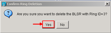


After the conversion, circuits in the circuit list still work, but there is no fiber or span protection. All the circuits utilize the original working path. If you require protection, delete each circuit. Then create each circuit with span protection. This includes circuits in the ACTIVE state.
Figure 11 – Working Circuit without Fiber or Span Protection 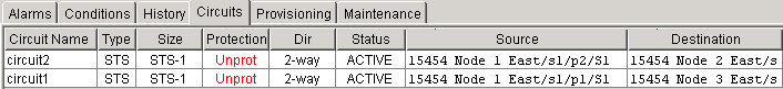
 Caution: Software and hardware changes can both impact traffic. Span or fiber path protection is not available after the ring conversion, except on circuits created after the conversion. Carry out the work during the maintenance window to minimize impact.
If you need to back out the BLSR to UPSR conversion, complete these steps:
-
Access Node 1 through CTC directly.
-
In node view, click the Maintenance > Database tabs.
-
Click Restore.
-
Locate the database file that resides on the hard drive of the workstation or on network storage.
-
Click to highlight the database file.
Figure 12 – Locate the Backup Database File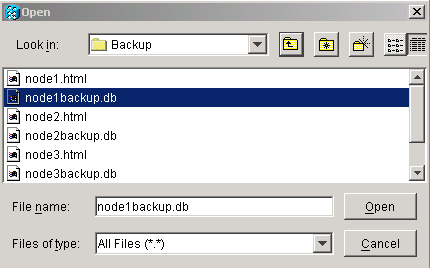
-
Click Open. The Database Info dialog box appears.
Figure 13 – Restore the Database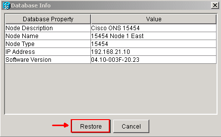
-
Click Yes.
-
The Restore Database box appears, and indicates that the restoration process is in progress.
Figure 14 – Database Restoration in Progress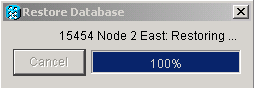
-
The Connection Lost box appears when the restoration process is complete.
Figure 15 – Database Restore Completed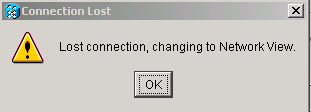
-
Click OK.
-
Repeat steps 1 through 10 for Nodes 2, 3 and 4.


Related Information
 Feedback
Contact Cisco
- Open a Support Case

- (Requires a Cisco Service Contract)