Feedback
Table Of Contents
Monitoring the System and Services
Assigning and Unassigning Alarms
Creating a Device Utilization Report
Viewing Saved Utilization Reports
Viewing Scheduled Utilization Runs
Monitoring Wireless Clients Using Maps
Monitoring Wireless Clients Using Search
Monitoring Wi-Fi TDOA Receivers
Monitoring the System and Services
This chapter describes how to monitor the mobility services engine by configuring and viewing alarms, events, and logs as well as how to generate reports on system use and element counts (tags, clients, rogue clients, and access points).
It also describes how to use Cisco WCS to monitor clients (wired and wireless), tags, chokepoints, and Wi-Fi TDOA receivers.
This chapter contains the following sections:
•
Monitoring Wi-Fi TDOA Receivers
Working with Alarms
This section describes how to view, assign, and clear alarms and events on a mobility services engine using Cisco WCS. It also describes how to define alarm notifications (all, critical, major, minor, warning) and detail how to email those alarm notifications.
Viewing Alarms
To view mobility services engine alarms, follow these steps:
Step 1
Step 2
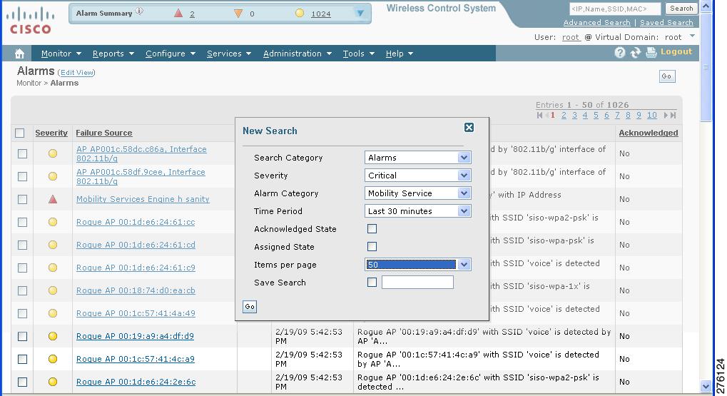
Figure 8-1 Advanced Search Alarm Panel
Step 3
Step 4
Step 5
Step 6
Options range from minutes (5, 15, and 30) to hours (1 and 8) to days (1 and 7). To display all, select Any time.
Step 7
Step 8
Step 9
Step 10
Note
Step 11
Note
Step 12
Assigning and Unassigning Alarms
To assign and unassign an alarm to yourself, follow these steps:
Step 1
Step 2
Note
Step 3
If you choose Assign to Me, your username appears in the Owner column. If you choose Unassign, the username column becomes empty.
Deleting and Clearing Alarms
If you delete an alarm, Cisco WCS removes it from its database. If you clear an alarm, it remains in the Cisco WCS database, but in the Clear state. You should clear an alarm when the condition that caused it no longer exists.
To delete or clear an alarm from a mobility services engine, follow these steps:
Step 1
Step 2
Step 3
Emailing Alarm Notifications
Cisco WCS lets you send alarm notifications to a specific email address. Sending notifications through email enables you to take prompt action when needed.
You can choose the alarm severity types (critical, major, minor, and warning) to have emailed to you.
To send alarm notifications, follow these steps:
Step 1
Step 2
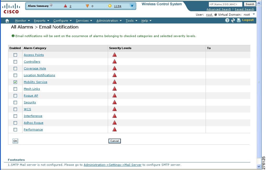
Figure 8-2 All Alarms > Email Notification Window
Note
Step 3
Note
Step 4
Step 5
Step 6
Step 7
You are returned to the Alarms > Notification window. The changes to the reported alarm severity levels and the recipient email address for email notifications are displayed.
Working with Events
You can use Cisco WCS to view mobility services engine and location notification events. You can search and display events based on their severity (critical, major, minor, warning, clear, and info) and event category.
You can search by the following event categories:
•
•
•
•
•
Additionally, you can search for an element's events by its IP address, MAC address, or name.
A successful event search displays the event severity, failure object, date and time of the event, and any messages for each event.
To display events, follow these steps:
Step 1
Step 2
•
•
Step 3
Note
Working with Logs
This section describes how to configure logging options and how to download log files.
Configuring Logging Options
You can use Cisco WCS to specify the logging level and types of messages to log.
To configure logging options, follow these steps:
Step 1
Step 2
Step 3
Step 4
Caution
Step 5
Step 6
Downloading Log Files
If you need to analyze mobility services engine log files, you can use Cisco WCS to download them to your system. Cisco WCS downloads a zip file containing the log files.
To download a zip file containing the log files, follow these steps:
Step 1
Step 2
Step 3
Step 4
Step 5
Generating Reports
In Cisco WCS, you can generate a device utilization and location utilization report for a mobility services engine. By default, reports are stored on the Cisco WCS server.
Once you define the report criteria, you can save the device and location utilization reports for future diagnostic use and run them on either an ad hoc or scheduled basis.
You can define the following criteria for a device utilization report:
•
•
•
•
You can view the following in a location utilization report:
•
•
Creating a Device Utilization Report
To create a device utilization report for the mobility services engine, follow these steps:
Step 1
Step 2
Step 3
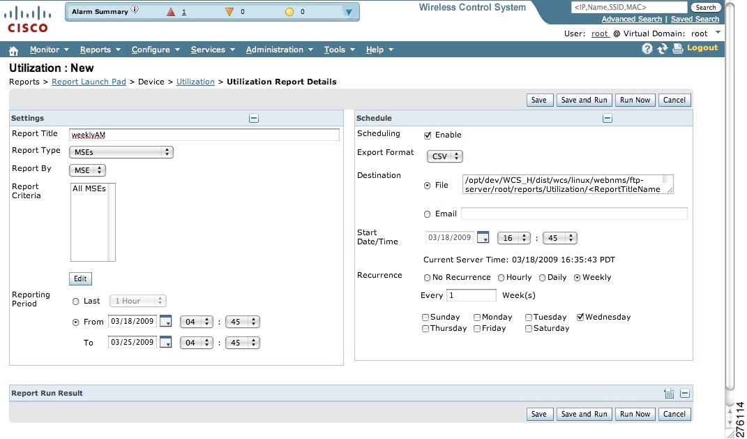
Figure 8-3 Device > Utilization Window
Step 4
Step 5
Step 6
Step 7
Note
Step 8
Step 9
Step 10
–
–
Step 11
Step 12
Step 13
Note
Step 14
•
•
–
•
Note
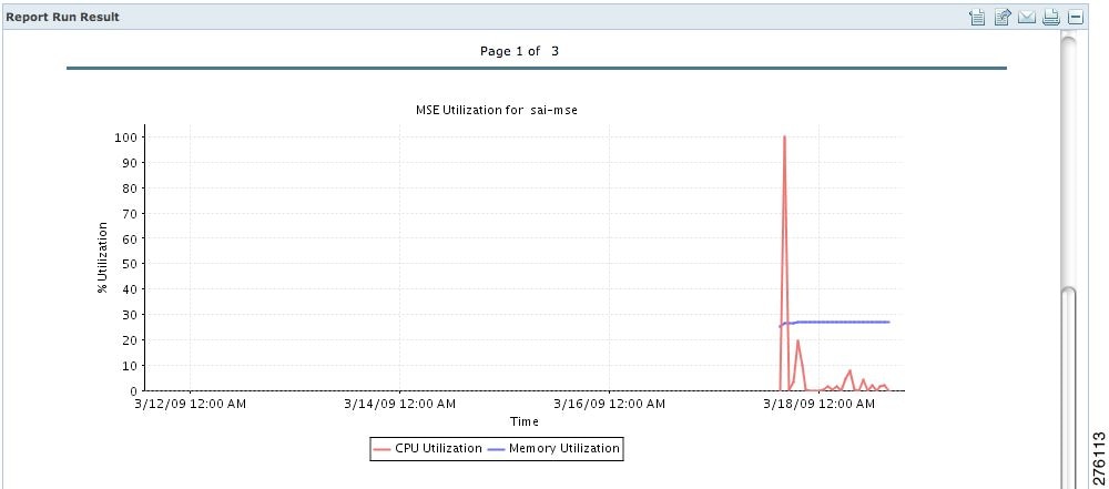
The results appear at the bottom of the window (see Figure 8-4).
Note
Figure 8-4 Devise > MSE Utilization > Results
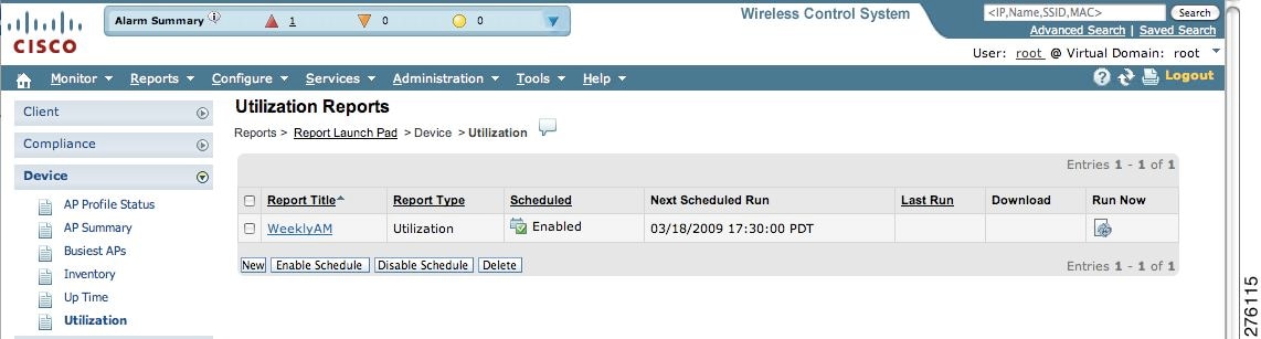
Step 15
Figure 8-5 Utilization Reports Summary Window
If the report is scheduled, it is shown as enabled and the next scheduled run date is noted.
If the report has run and is not scheduled to run again, it is shown as expired.
If the report has run and is scheduled to run again, it is shown as disabled.
Step 16
Viewing Saved Utilization Reports
To download a saved report, follow these steps:
Step 1
Step 2
Viewing Scheduled Utilization Runs
To review status for a scheduled report, follow these steps:
Step 1
Step 2
Step 3
Monitoring Wireless Clients
Monitoring Wireless Clients Using Maps
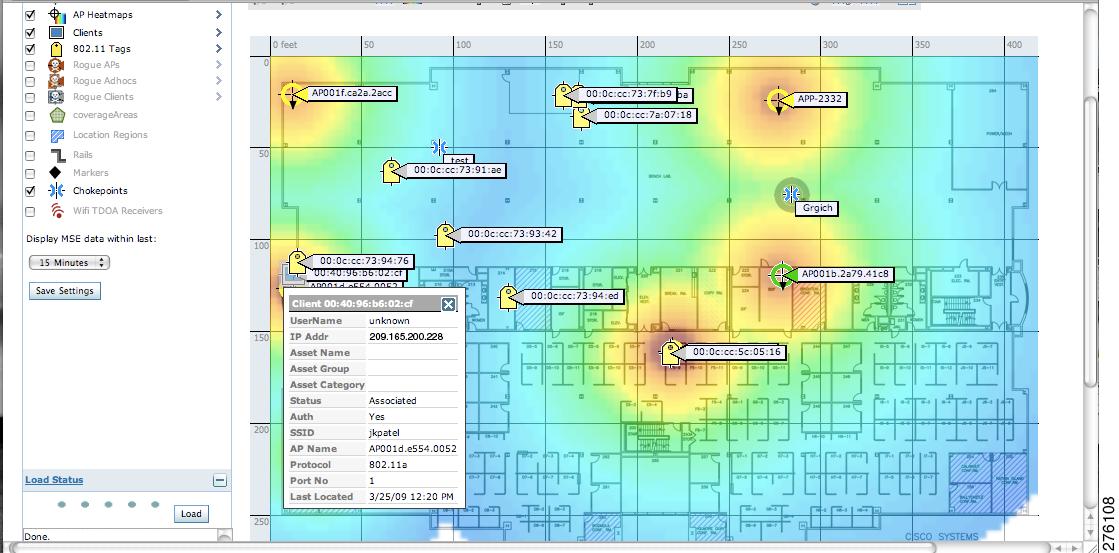
On a Cisco WCS map, you can view the name of the access point that generated the signal for a client, its strength of signal, and when the location information was last updated for the client. Move the cursor over the client icon on the map to display this information.
You can also view the client details window, which provides statistics (such as client association, client RSSI, and client SNR), packets transmitted and received values, events, and security information for that client.
To determine a client's location status on a map and view its client details window using maps, follow these steps:
Step 1
Step 2
Step 3
Note
Figure 8-6 Monitor > Maps > Building > Floor Window
Step 4
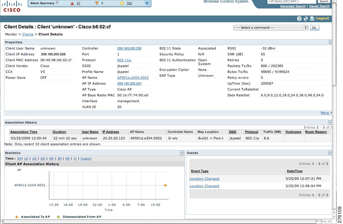
Step 5
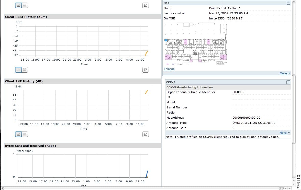
Figure 8-7 Client Details Window (1 of 2)
Figure 8-8 Client Details Window (2 of 2)
Monitoring Wireless Clients Using Search
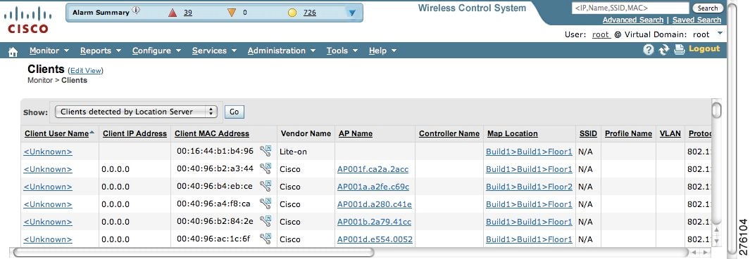
You can view client information in summary and in detail at the Monitor > Clients window and on maps (Monitor > Maps).
To view client information, follow these steps:
Step 1
The Clients summary window appears.
Step 2
A summary of all clients detected by all mobility services engines and location appliances managed by Cisco WCS displays (see Figure 8-9).
Figure 8-9 Monitor > Clients Window
a.
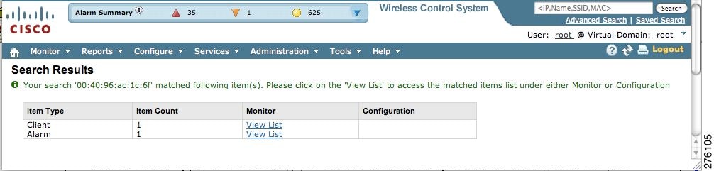
For example, if you enter a MAC address in the search field, the following window appears (see Figure 8-10).
Figure 8-10 Search by MAC address Results
1.
2.
Figure 8-11 Alarm Summary for Client
Note
b.
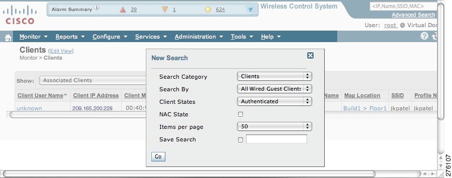
You can further define the client category by: all clients, all excluded clients, all wired guest clients, and all logged in clients using the Search By drop-down menu (see Figure 8-12).
Figure 8-12 Advanced Search Window
Step 3
Monitoring Tags
You can monitor tag status and location on Cisco WCS maps as well as review tag details on the Monitor > Tags window. You can also use Advanced Search to monitor tags.
Monitoring Tags Using Maps
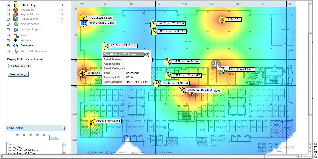
On a Cisco WCS map, you can view the name of the access point that generated the signal for a tagged asset, its strength of signal, and when the location information was last updated for the asset. Move the cursor over the tag icon on the map to display this information.
To enable tag location status on a map, follow these steps:
Step 1
Step 2
Step 3
Note
Figure 8-13 Monitor > Maps > Building > Floor > Tag Window
Step 4
Step 5
Figure 8-14 Tag Details Window
Step 6
Figure 8-15 Tag Location History Window
Monitoring Tags Using Search
You can search for tags by asset type (name, category and group), by MAC address, by system (controller or MSE), and by area (floor area and outdoor area).
You can further refine your search using the Advanced search parameters and save the search criteria for future use. Choose Saved Searches located in the navigation bar to retrieve saved searches.
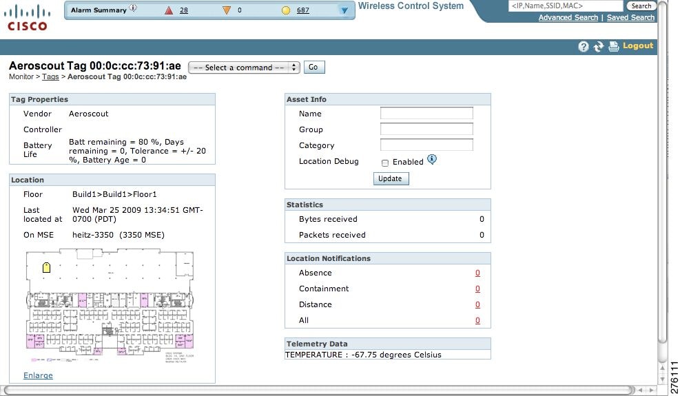
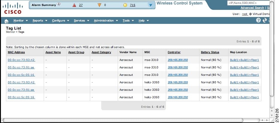
When you click on the MAC address of a tag location in a search results window, the following details appear for the tag:
•
•
•
–
•
•
•
•
•
To search for tags, follow these steps:
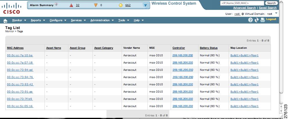
Step 1
Figure 8-16 Monitor > Tags Window
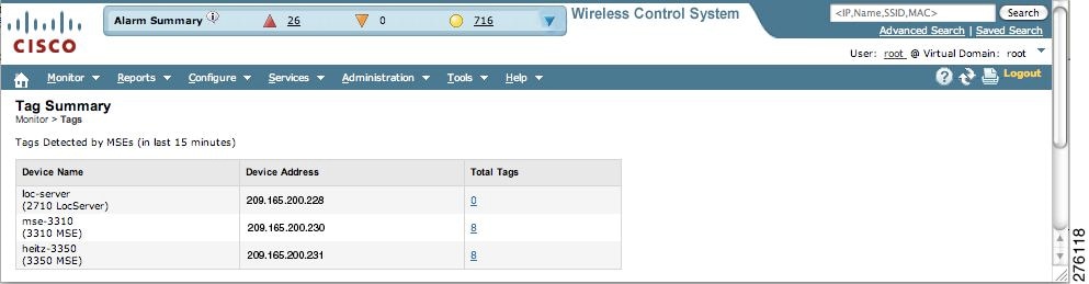
a.
Figure 8-17 Total Tags Listing by Mobility Services Engine
Note
b.
c.
1.
2.
3.
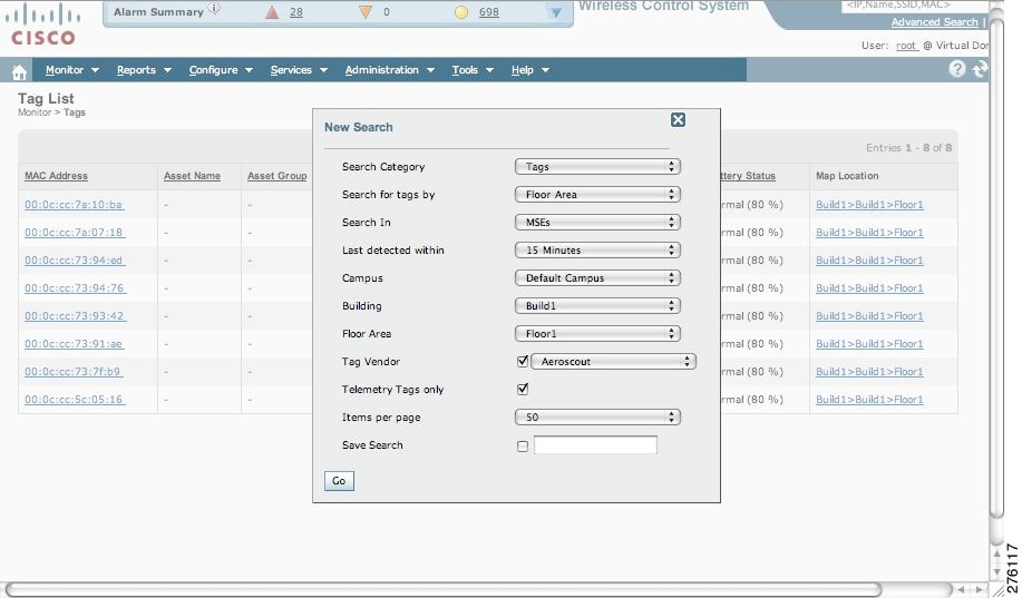
Note
Figure 8-18 Advanced Search Panel for Tags
Figure 8-19 Advanced Search Results for Tag
Note
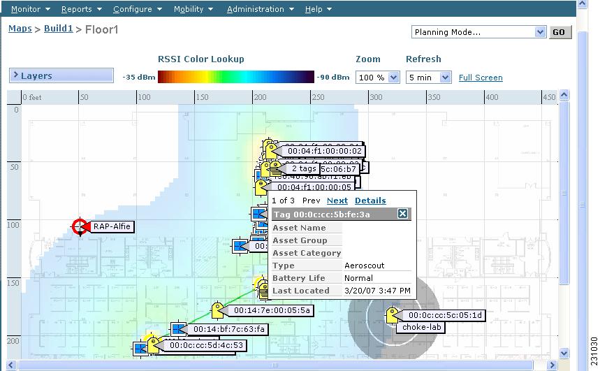
Overlapping Tags
When multiple tags are within close proximity of one another a summary tag is used to represent their location on a WCS map (Monitor > Maps). The summary tag is labeled with the number of tags at that location.
When you move the mouse over the overlapping tag on the map, a panel appears with summary information for the overlapping tags (see Figure 8-20).
Select the Prev and Next links to move between the individual tag summary panels. To see detailed information on a specific tag, select the Details link while viewing the tag's summary information.
Note
•
–
–
Figure 8-20 Overlapping Tags Window
Monitoring Chokepoints
A chokepoint must be assigned to a map for its location to be monitored.
Refer to the "Adding Chokepoints to the Cisco WCS" section on page 7-13 of this configuration guide. After adding the TDOA receiver to a map, you must resynchronize the network designs (Services > Synchronize Services) with the mobility services engine for it to appear on the map.
If a chokepoint is not assigned to a map, you are not able to find that chokepoint using Search or Advanced Search.
All chokepoint setup is done using the AeroScout System Manager.
Note
To monitor chokepoints, follow these steps:
Step 1
Step 2
a.
Figure 8-21 Search for Chokepoint by MAC Address
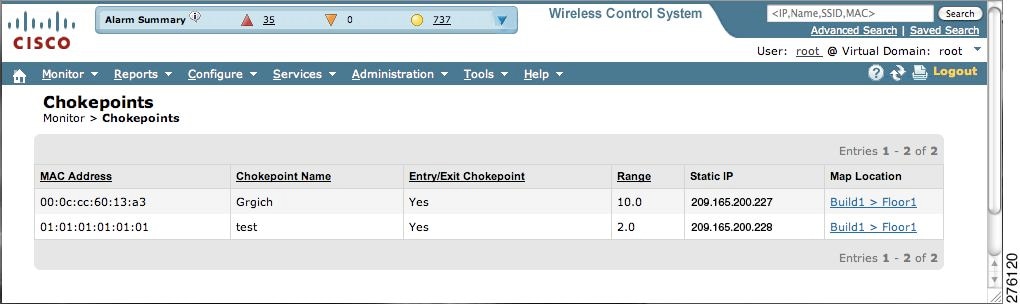
This example show a search by MAC address (see Figure 8-22).
If no match exists, a message appears in the results window.
Figure 8-22 MAC Address Search Results for a Chokepoint Indicating a Match
b.
1.
2.
3.
4.
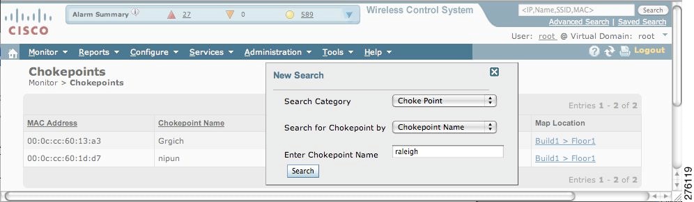
This example shows an advanced search using the chokepoint name (see Figure 8-23).
Figure 8-23 Chokepoint Name Advanced Search Panel
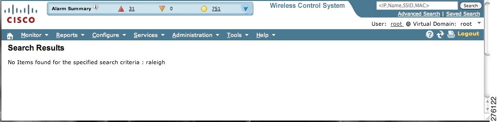
If no match exists, a message appears in the window (see Figure 8-24).
Otherwise the search result appears.
Figure 8-24 Chokepoint Advanced Search Results Indicating No Match
Monitoring Wi-Fi TDOA Receivers
A Wi-Fi TDOA receiver must be assigned to a map for its location to be monitored.
Refer to the "Adding Wi-Fi TDOA Receivers to Cisco WCS" section on page 7-19 of this configuration guide. After adding the TDOA receiver to a map, you must resynchronize network designs (Services > Synchronize Services) with the mobility services engine for it to appear on the map.
If a TDOA receiver is not assigned to a map, you cannot find it using Search or Advanced Search.
All TDOA receiver setup is done using the AeroScout System Manager.
Note
To monitor TDOA Receivers, follow these steps:
Step 1
Step 2
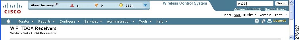
a.
Figure 8-25 Monitor > WiFi TDOA Receivers Search Window
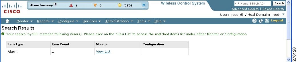
Figure 8-26 shows an example of advanced search using the TDOA Wi-Fi receiver name. Click View List to see a full list of Alarms.
If no match exists, a message appears in the results window.
Figure 8-26 Search Results Window
b.
1.
2.
3.
4.
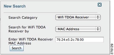
This example shows an advanced search using the MAC address (see Figure 8-27).
Figure 8-27 Advanced Search Panel
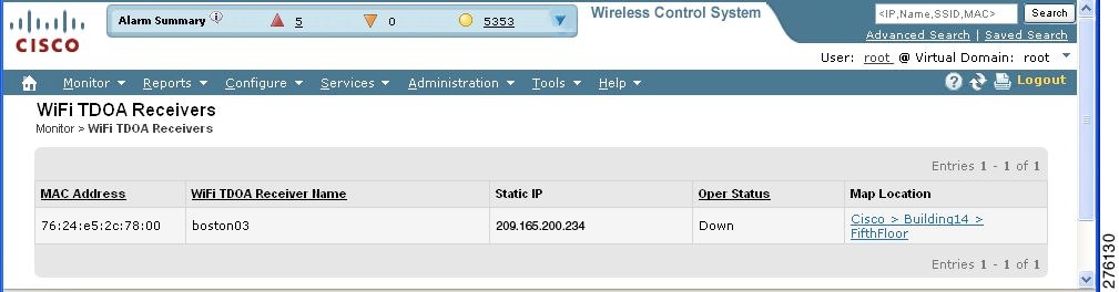
Figure 8-28 shows the search results.
If no match exists, a message appears in the results window.
Figure 8-28 WiFi TDOA Receivers Advanced Search Results Indicating a Match
Monitoring Wired Switches
You can review details on the wired switch (IP address, serial number, software version, and ELIN), its ports, its wired clients (count and status), and its civic information.
Wired switch data is downloaded to the mobility services engine through Cisco WCS when the Ethernet switch and the mobility services engine are synchronized (Services > Synchronize Services > Switches). Communications between a location-capable switch and a mobility services engine is over NMSP. Cisco WCS and the mobility services engine communicate over XML.
To view details on wired switches, follow these steps:
Step 1
Step 2
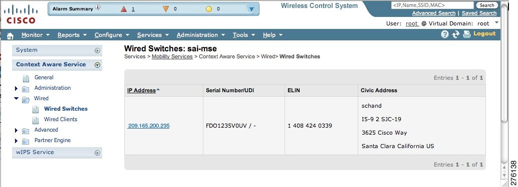
Step 3
Figure 8-29 Context Aware Service > Wired Switches Window
Step 4
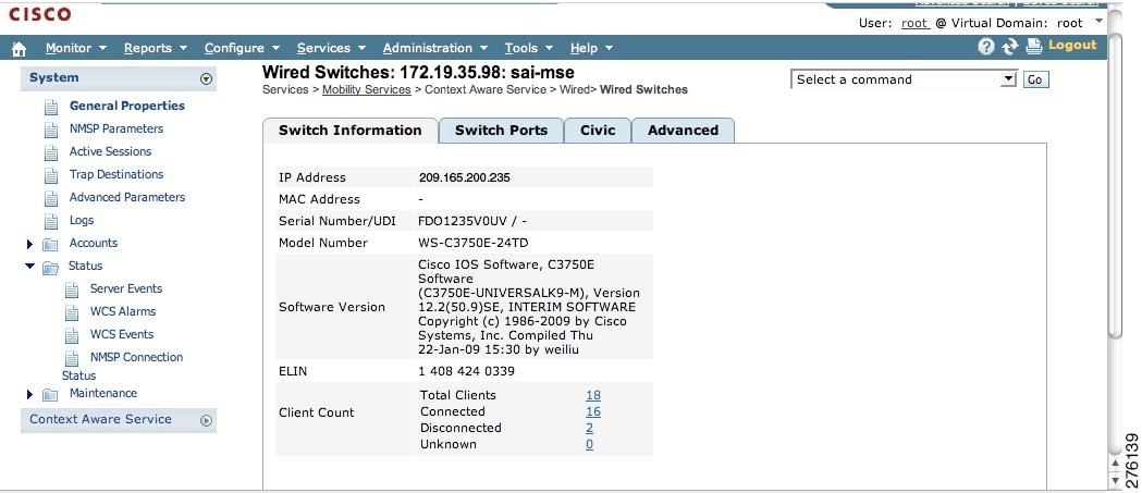
Figure 8-30 Wired > Wired Switches > IP Address Window
Note
On the Switch Information tab, a total count of wired clients connected to the switch is summarized along with their state (connected, disconnected, and unknown).
•
•
•
You can view detailed wired client information by clicking on one of the client count links (total clients, connected, disconnected, and unknown). Refer to the "Monitoring Wired Clients" section for details.
Step 5
Note
Figure 8-31 Wired Switches > Switch Ports Window
Step 6
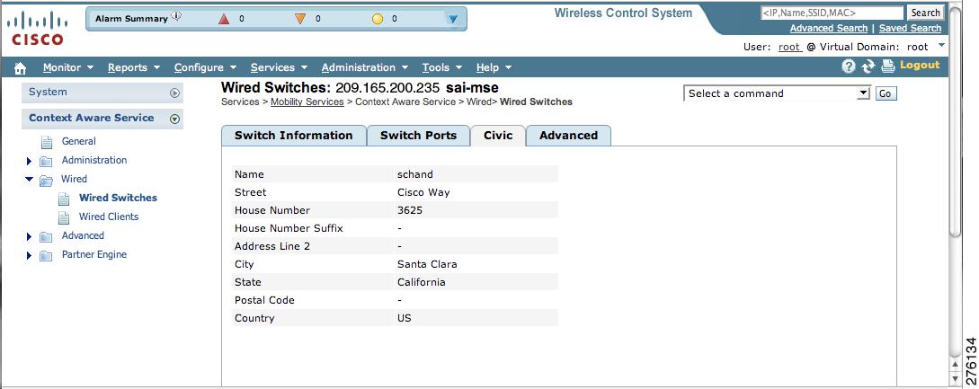
Figure 8-32 Wired Switches > Civic Window
Step 7
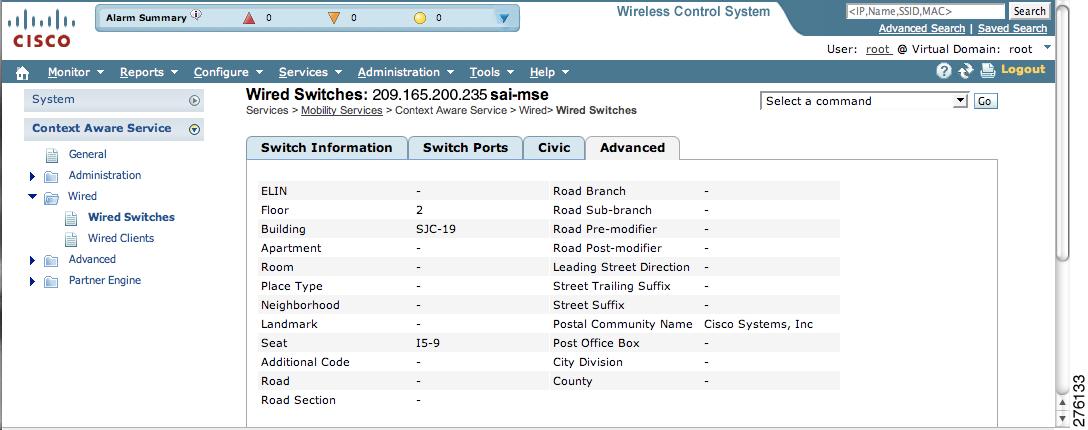
Figure 8-33 Wired Switches > Advanced Window
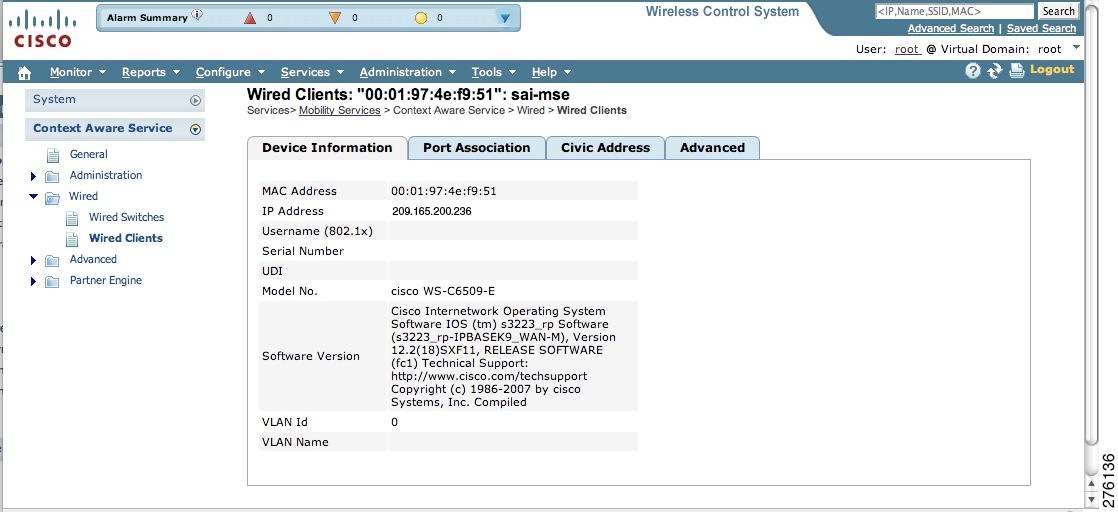
Monitoring Wired Clients
You can view details on a wired client (MAC address, IP address, username, serial number, UDI, model no., software version, VLAN ID, and VLAN ID), its port, and its civic information.
Wired client data is downloaded to the mobility services engine through Cisco WCS when the switch and the mobility services engine are synchronized (Services > Synchronize Services > Switches).
Communications between a location-capable switch and a mobility service engine is over NMSP. Cisco WCS and the mobility services engine communicate over XML.
You can view wired clients' details on either the wired switches window (Context Aware Service > Wired > Wired Switches) or wired clients window (Context Aware Service > Wired > Wired Clients).
•
•
To view details on a wired client, follow these steps:
Step 1
Step 2
Step 3
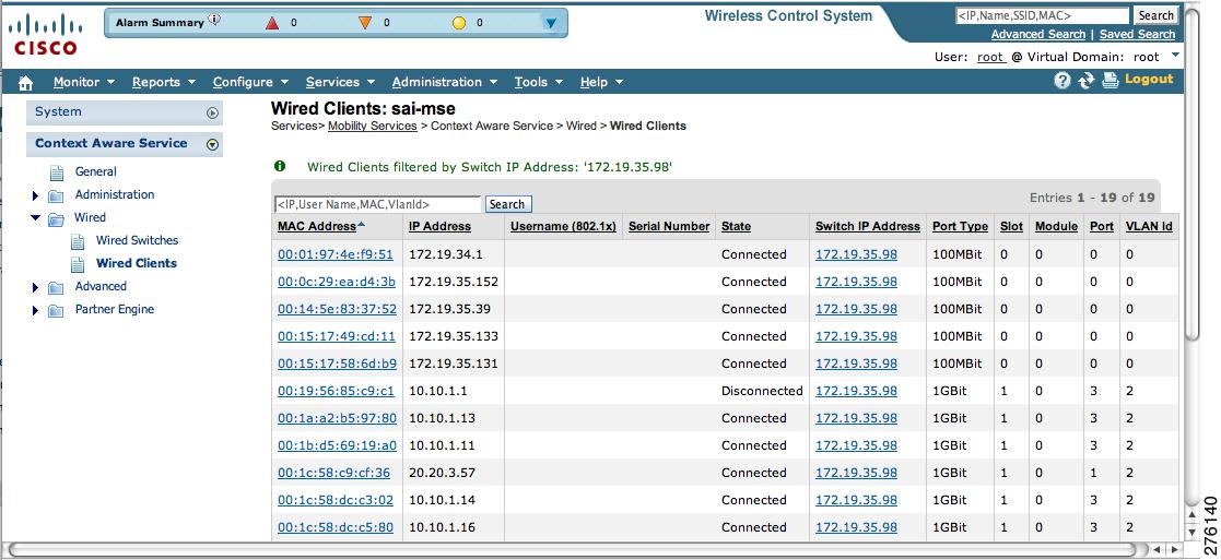
Figure 8-34 Wired > Wired Clients Window
At the Wired Clients summary window, clients are grouped by their switch (see Figure 8-34).
A client's status is noted as connected, disconnected, or unknown. Definitions are summarized below:
•
•
•
•
–
•
Figure 8-35 Wired Clients > Device Information Window
Step 4
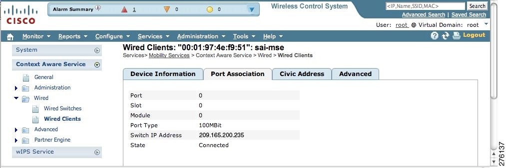
Figure 8-36 Wired Clients > Port Association Window
Step 5
Step 6
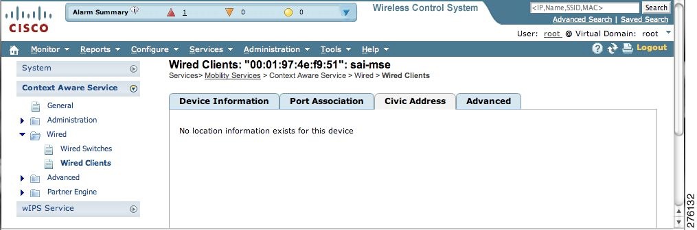
Note
Figure 8-37 Wired Clients > Civic Address Window
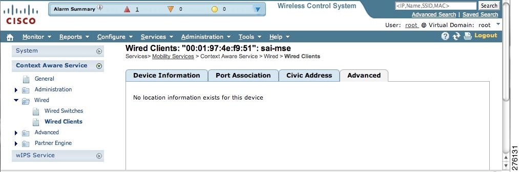
Figure 8-38 Wired Clients > Advanced Window