[an error occurred while processing this directive]

Cisco Unity

NEC NEAX 2400 IMX Serial MCI TIMG Integration Guide for Cisco Unity 4.2

 Feedback

Table Of Contents

NEC NEAX 2400 IMX Serial MCI TIMG Integration Guide for Cisco Unity 4.2

Integration Tasks

Task List to Create the Integration

Requirements

Integration Description

Call Information

Integration Functionality

Integrations with Multiple Phone Systems

Planning How the Voice Messaging Ports Will Be Used by Cisco Unity

Configuring the T1 Digital Trunk Interface Card

Programming the NEC NEAX 2400 IMX Phone System

Setting Up the TIMG Units

Downloading and Installing the Required Cisco Unity ES File (Cisco Unity 4.2(1) Only)

Creating an Integration with the Phone System

Testing the Integration

Integrating a Secondary Server for Cisco Unity Failover

Requirements

Integration Description

Setting Up the Secondary Server for Failover


Appendix: Documentation and Technical Assistance

Conventions

Obtaining Documentation, Obtaining Support, and Security Guidelines


NEC NEAX 2400 IMX Serial MCI TIMG Integration Guide for Cisco Unity 4.2


Revised January 8, 2009

This document provides instructions for integrating the NEC NEAX 2400 IMX phone system with Cisco Unity 4.2 by using TIMG units (T1 media gateways), T1 digital lines (DS1 or "dry T1" digital lines only), and an RS-232 serial cable.

Integration Tasks

Before doing the following tasks to integrate Cisco Unity with the NEC NEAX 2400 IMX phone system by using the TIMG units (T1 media gateways), confirm that the Cisco Unity server is ready for the integration by completing the applicable tasks in the applicable Cisco Unity installation guide.

The following task list describes the process for creating the integration.

Task List to Create the Integration

Use the following task list to set up a new integration with the NEC NEAX 2400 IMX phone system. If you are installing a new Cisco Unity server by using the applicable Cisco Unity installation guide, you may have already completed some of the following tasks.

1. Review the system and equipment requirements to confirm that all phone system and Cisco Unity server requirements have been met. See the "Requirements" section.

2. Plan how the voice messaging ports will be used by Cisco Unity. See the "Planning How the Voice Messaging Ports Will Be Used by Cisco Unity" section.

3. Configure the T1 digital interface card. See the "Configuring the T1 Digital Trunk Interface Card" section.

4. Program the NEC NEAX 2400 IMX phone system and extensions. See the "Programming the NEC NEAX 2400 IMX Phone System" section.

5. Set up the TIMG units. See the Setting Up the TIMG Units.

6. (Cisco Unity 4.2(1) only) Download and install the required Cisco Unity ES file. See the Downloading and Installing the Required Cisco Unity ES File (Cisco Unity 4.2(1) Only).

7. Create the integration. See the Creating an Integration with the Phone System.


Caution Do not edit the phone configuration file (also known as the switch ini file) to customize this integration. If you change the settings in this file, the integration may not function correctly.

8. Test the integration. See the Testing the Integration.

9. If you have a secondary server for Cisco Unity failover, integrate the secondary server. See the "Integrating a Secondary Server for Cisco Unity Failover" section.

Requirements

The NEC NEAX 2400 IMX integration supports configurations of the following components:

Phone System

The NEC NEAX 2400 IMX phone system.

MCI feature II.

T1 digital trunk interface card (card number PA-24DTR/DLI) for each group of 24 voice messaging ports. (Note that the card must be validated before programming the phone system.)

The firmware must be configured to support T1 line-side signaling.

T1 CAS connections to the TIMG units by using the FXS/FSO or E&M protocol.

One or more TIMG units (media gateways). For details, refer to the "Supported Phone System Integrations Through PIMG/TIMG Units" section in the applicable Supported Hardware and Software, and Support Policies for Cisco Unity at http://www.cisco.com/en/US/products/sw/voicesw/ps2237/prod_installation_guides_list.html.

The serial data port on the phone system connected to the serial port on the master TIMG unit with an RS-232 serial cable (which is available from Cisco).

Specifications for the serial cable are in Connecting PBX-IP Media Gateway (PIMG) to the Serial Port of a PBX at http://www.dialogic.com/support/helpweb/mg/tn117.htm.

We recommend that the serial cable have the following construction:

A maximum of 50 feet (15.24 m) in length

24 AWG stranded conductors

Low capacitance—for example, no more than 12 pF/ft (39.4 pF/m) between conductors

At least 65 percent braided shield over aluminized polymer sleeve around conductors

UL-recognized overall cable jacket insulation with low dielectric constant

Braided shield fully terminated to and enclosed by a metal connector backshell

Gold-plated connector contacts

The voice messaging ports in the phone system connected by T1 digital lines (DS1 or "dry T1" digital lines only) to the ports on the TIMG units.


Caution T1 (or "wet T1") connections to the PSTN must be through an MTU, CSU, or other device that provides line isolation. Otherwise, the TIMG units may be damaged.

The TIMG units connected to the same LAN or WAN that Cisco Unity is connected to.

If the TIMG units connect to a WAN, the requirements for the WAN network connections are:

For G.729a codec formatting, a minimum of 32.76 Kbps guaranteed bandwidth for each voice messaging port.

For G.711 codec formatting, a minimum of 91.56 Kbps guaranteed bandwidth for each voice messaging port.

No network devices that implement network address translation (NAT).

A maximum 200 ms network latency.

The phone system ready for the integration, as described in the documentation for the phone system.

Cisco Unity Server

Cisco Unity 4.2 installed and ready for the integration, as described in the applicable Cisco Unity installation guide at http://www.cisco.com/en/US/products/sw/voicesw/ps2237/prod_installation_guides_list.html.

For Cisco Unity 4.2(1) only, the latest ES installed.

A license that enables the applicable number of voice messaging ports.

Integration Description

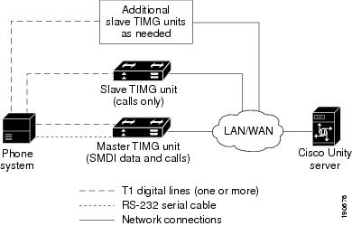
The NEC NEAX 2400 IMX integration sends call information and MWI requests through the data link, which is an RS-232 serial cable that connects the phone system and the master TIMG unit. Voice connections are sent through the T1 digital lines between the phone system and the TIMG units. The TIMG units communicate with the Cisco Unity server through the LAN or WAN by using Session Initiation Protocol (SIP). Figure 1 shows the required connections.

Figure 1 Connections Between the Phone System and Cisco Unity

Call Information

The phone system sends the following information with forwarded calls:

The extension of the called party

The extension of the calling party (for internal calls) or the phone number of the calling party (if it is an external call and the system uses caller ID)

The reason for the forward (the extension is busy, does not answer, or is set to forward all calls)

Cisco Unity uses this information to answer the call appropriately. For example, a call forwarded to Cisco Unity is answered with the personal greeting of the subscriber. If the phone system routes the call to Cisco Unity without this information, Cisco Unity answers with the opening greeting.

Integration Functionality

The NEC NEAX 2400 IMX integration with Cisco Unity provides the following integration features:

Call forward to personal greeting

Call forward to busy greeting

Caller ID

Easy message access (a subscriber can retrieve messages without entering an ID because Cisco Unity identifies the subscriber based on the extension from which the call originated; a password may be required)

Identified subscriber messaging (Cisco Unity identifies the subscriber who leaves a message during a forwarded internal call, based on the extension from which the call originated)

Message waiting indication (MWI)

Supervised Transfer for Calls

When supervised transfer is enabled and a caller hangs up while being transferred to another phone, the called phone will ring briefly even though there is no call. If the ringing phone is answered, there will be no call, only dead air will be heard.

Integrations with Multiple Phone Systems

Cisco Unity 4.2 can be integrated with two or more phone systems at one time. For information on the maximum supported combinations and instructions for integrating Cisco Unity with multiple phone systems, refer to the Multiple Phone System Integration Guide for Cisco Unity 4.2 at http://cisco.com/en/US/products/sw/voicesw/ps2237/products_installation_and_configuration_guides_list.html.

Planning How the Voice Messaging Ports Will Be Used by Cisco Unity

Before programming the phone system, you need to plan how the voice messaging ports will be used by Cisco Unity. The following considerations will affect the programming for the phone system (for example, setting up the hunt group or call forwarding for the voice messaging ports):

The number of voice messaging ports installed.

The number of voice messaging ports that will answer calls.

The number of voice messaging ports that will only dial out, for example, to send message notification, to set message waiting indicators (MWIs), to make AMIS deliveries, and to make telephone record and playback (TRAP) connections.

The following table describes the voice messaging port settings in Cisco Unity that can be set in UTIM, and that are displayed as read-only text on the System > Ports page of the Cisco Unity Administrator.

Table 1 Settings for the Voice Messaging Ports 

Field
Considerations

Extension

Enter the extension for the port as assigned on the phone system.

Enabled

Check this check box to enable the port. The port is enabled during normal operation.

Uncheck this check box to disable the port. When the port is disabled, calls to the port get a ringing tone but are not answered. Typically, the port is disabled only by the installer during testing.

Answer Calls

Check this check box to designate the port for answering calls. These calls can be incoming calls from unidentified callers or from subscribers.

Message Notification

Check this check box to designate the port for notifying subscribers of messages. Assign Message Notification to the least busy ports.

Dialout MWI

(not used by serial integrations)

Do not check this check box. Otherwise, the integration may not function correctly.

AMIS Delivery

(available with the AMIS licensed feature only)

Check this check box to designate the port for making outbound AMIS calls to deliver voice messages from Cisco Unity subscribers to users on another voice messaging system. Cisco Unity supports the Audio Messaging Interchange Specification (AMIS) protocol, which provides an analog mechanism for transferring voice messages between different voice messaging systems.

This setting affects outbound AMIS calls only. All ports are used for incoming AMIS calls.

Because the transmission of outgoing AMIS messages may tie up voice ports for long periods of time, you may want to adjust the schedule on the Network > AMIS > Schedule page so that outgoing AMIS calls are placed during closed hours or at times when Cisco Unity is not processing many calls.

TRAP Connection

Check this check box so that subscribers can use the phone as a recording and playback device in Cisco Unity web applications and e-mail clients. Assign TRAP Connection to the least busy ports.


The Number of Voice Messaging Ports to Install

The number of voice messaging ports to install depends on numerous factors, including:

The number of calls Cisco Unity will answer when call traffic is at its peak.

The expected length of each message that callers will record and that subscribers will listen to.

The number of subscribers.

The number of ports that will be set to dial out only.

The number of calls made for message notification.

The number of MWIs that will be activated when call traffic is at its peak.

The number of AMIS delivery calls.

The number of TRAP connections needed when call traffic is at its peak. (TRAP connections are used by Cisco Unity web applications to play back and record over the phone.)

The number of calls that will use the automated attendant and call handlers when call traffic is at its peak.

It is best to install only the number of voice messaging ports that are needed so that system resources are not allocated to unused ports.

The Number of Voice Messaging Ports That Will Answer Calls

The calls that the voice messaging ports answer can be incoming calls from unidentified callers or from subscribers. Typically, the voice messaging ports that answer calls are the busiest.

You can set voice messaging ports to both answer calls and to dial out (for example, to send message notifications). However, when the voice messaging ports perform more than one function and are very active (for example, answering many calls), the other functions may be delayed until the voice messaging port is free (for example, message notifications cannot be sent until there are fewer calls to answer). For best performance, dedicate certain voice messaging ports for only answering incoming calls, and dedicate other ports for only dialing out. Separating these port functions eliminates the possibility of a collision, in which an incoming call arrives on a port at the same time that Cisco Unity takes the port off-hook to dial out.

The Number of Voice Messaging Ports That Will Only Dial Out, and Not Answer Calls

Ports that will only dial out and will not answer calls can do one or more of the following:

Notify subscribers by phone, pager, or e-mail of messages that have arrived.

Turn MWIs on and off for subscriber extensions.

Make outbound AMIS calls to deliver voice messages from Cisco Unity subscribers to users on another voice messaging system. (This action is available only with the AMIS licensed feature.)

Make a TRAP connection so that subscribers can use the phone as a recording and playback device in Cisco Unity web applications.

Typically, these voice messaging ports are the least busy ports.


Caution In programming the phone system, do not send calls to voice messaging ports in Cisco Unity that cannot answer calls (voice messaging ports that are not set to Answer Calls). For example, if a voice messaging port is set only to Dialout MWI, do not send calls to it.

Preparing for Programming the Phone System

Record your decisions about the voice messaging ports to guide you in programming the phone system.

Configuring the T1 Digital Trunk Interface Card

Do the following procedure.

To Set the T1 Digital Trunk Interface Card DIP Switches


Step 1 Remove the 24DTR/DLI digital trunk interface card from the phone system.

On the SW10/4D switch, set the number 7 DIP switch to the Off position (B8ZS).

Step 2 Place the 24DTR/DLI digital trunk interface card into the phone system.


For more information on the settings for the 24DTR/DLI T1 digital trunk interface card, see the NEAX 2400 IMX Circuit Card Manual.

Programming the NEC NEAX 2400 IMX Phone System

Instruct the phone system technician to set up the phone system in the manner directed in the following procedure.

To Program the NEC NEAX 2400 IMX Phone System for a Serial TIMG Integration with Cisco Unity


Step 1 Program the phone lines connecting to the voice messaging ports on the TIMG units as a multiline hunt group.

Make sure that the phone system sends calls only to Cisco Unity voice messaging ports that are set to Answer Calls. Calls sent to a voice port not set to Answer Calls cannot be answered by Cisco Unity and may cause other problems.

Step 2 Enable hookflash transfer capability on each phone line that connects to the voice messaging ports on the TIMG units.

Step 3 Enable caller ID (through the serial data link to the master TIMG unit) on each subscriber extension.


Caution The phone system just provide caller ID through the serial data link to the master TIMG unit. Otherwise, some integration features will not function correctly.

Step 4 For each subscriber extension, set the call forwarding options to the following:

Unrestricted source

Forward when the extension is not answered

Forward when the extension is busy


The following phone system programming is provided as an example. The specific programming for your phone system may vary depending on its configuration.

Example of Programming for the NEC NEAX 2400 IMX Phone System in a TIMG Integration

1. Use the AUCD command to program the phone system to send UCD call information to MCI. Assign a value of "0" to the "MCI Data Transfer" field for the applicable tenant and UCD pilot numbers.

2. Use the programming system data table to program the ASYD settings. Each bit is part of a hexadecimal number displayed in the ASYD settings. Convert the hexadecimal number to binary to determine the individual settings.

Table 2 Programming System Data 

System
Index
Bit
Value
Description

1

17

b4

1

Release (blind) transfer to attendant console

28

b0-4

0

Guard timer not required

b5

1

MWI controlled by MCI

29

b1-7

0/1

No/Yes: Assign I/O port for MCI output

Port 1 = b1, port 2 = b2, and so on

34

b1-4

0

Set output to no parity and 1 stop bit

60

b3

0

UCD queuing required

63

b0

1

Release transfer for stations in service

69

b0

1

No recall, execute call forwarding on no answer

70

b0

1

Called number display, when forwarding to attendant console

78

b0

1

Calling number display enabled

b1

1

Called station status display enabled

238

b0-7

0

Lamp flash rate

246

b3

0

MCI expansion set to normal

400

b2

1

Calling number information sent to MCI

2

6

b0

1

MCI in service when terminating to a UCD group

7

b1

0

MCI out of service when terminating to attendant console


3. Use the programming system data local data table to program the ASYDL settings. Each bit is part of a hexadecimal number displayed in the ASYDL settings. Convert the hexadecimal number to binary to determine the individual settings.

Table 3 Programming System Data Local Data 

System
Index
Bit
Value
Description

1

641

b1

0/1

0/1: MCI/IMX station number/phone number

832

b0-7

00-FD

Assign the FPC of the node connected to MC

833

b0

0

MWI controlled by MCI


4. Use the ASDT command to add ports that will connect to the first voice messaging port on the first TIMG unit by entering the following settings.

Table 4 ASDT Command Settings for Adding Ports 

Field
Setting

TN

Enter the tenant number, which is typically 1.

STN

Enter the station number.

TEC

Enter 11 (which sets the port type as "voice mail").

RSC

Accept the default (all route options) or enter another route service class.

SFC

Accept the default (all options) or enter another service feature class.


5. In the WRT field, enter Y and press Enter.

6. Repeat Step 4. and Step 5. for all remaining ports that will connect to the voice messaging ports on the TIMG unit.

7. Repeat Step 6. for all remaining TIMG units.

8. Use the ASHU command to add the UCD hunt group access number (a real or virtual extension number) by entering the following settings.

Table 5 ASHU Command Settings for Adding the Hunt Group Access Number 

Field
Setting

TN

Enter the tenant number, which is typically 1.

STN

Enter the access number. for the hunt group.

Edit STN

Enter the extensions for each voice messaging port on the TIMG units, pressing Enter after each extension.


9. Click Set.

Setting Up the TIMG Units

Do the following procedures to set up the analog TIMG units (media gateways) that are connected to the phone system.

These procedures require that the following tasks have already been completed:

The phone system is connected to the TIMG units by using T1 digital lines and the applicable RS-232 serial cable.

The TIMG units are ready to be connected to the LAN or WAN.

The TIMG units are connected to a power source.

Fields that are not mentioned in the following procedures must keep their default values. For the default values of all fields, see the manufacturer documentation for the TIMG units.

To Download the TIMG Firmware Update Files for TIMG Units


Step 1 On a Windows workstation that will have access to the TIMG units, open a web browser and go to the Cisco Unity PIMG Software Download page at http://www.cisco.com/pcgi-bin/tablebuild.pl/unity-PIMG.


Note To access the software download page, you must be logged on to Cisco.com as a registered user.


Step 2 On the Cisco Unity PIMG Software Download page, click the most recent version of the firmware for your TIMG units.

Step 3 On the Details page, click Next.

Step 4 On the Document page, click Accept.

Step 5 In the Enter Network Password dialog box, enter your user name and password, then click OK.

Step 6 In the File Download dialog box, click Save.

Step 7 In the Save As dialog box, browse to the Windows workstation that will have access the TIMG units, browse to a directory where you want to save the file, and click Save.

Step 8 In the Download Complete dialog box, click Open. The window for extracting the TIMG firmware update files appears.

Step 9 Click Extract.

Step 10 In the Extract dialog box, browse to the directory where you want the extracted files, and click Extract.

Step 11 Close the window for the extracting application.


To Set Up the TIMG Units


Step 1 On the Windows workstation, add a temporary route to enable access to the TIMG units.

a. On the Windows Start menu, click Run.

b. Enter cmd, and press Enter. The Command Prompt window appears.

c. At the command prompt, enter route add 10.12.13.74 <IP Address of Workstation>, and press Enter.

For example, if the IP address of the workstation is 198.1.3.25, enter "route add 10.12.13.74<space>198.1.3.25" in the Command Prompt window.

d. Close the Command Prompt window.

Step 2 Connect a TIMG unit to the network.

Step 3 In the web browser, go to http://10.12.13.74.

Step 4 On the System Login page, enter the following case-sensitive settings.

Table 6 System Login Page Settings 

Field
Setting

Username

Enter admin.

Password

Enter IpodAdmin.


Step 5 Click Log On.

Step 6 On the Configure menu, click Upgrade.

Step 7 On the Upgrade page, click Browse.

Step 8 In the Choose File dialog box, browse to the directory on the Windows workstation that has the extracted TIMG firmware update files.

Step 9 Click Ls_<xx>.app (where <xx> is multiple digits), and click Open.

Step 10 On the Upgrade page, click Install.

Step 11 After the file is installed, a message prompting you to restart the TIMG unit appears. Click Cancel.


Caution Do not restart the TIMG unit until you are instructed to do so later in this procedure, even if the file installation fails. Restarting the TIMG unit at this step may prevent the TIMG unit from functioning correctly.

Step 12 Repeat Step 6 through Step 11 for the file Run_<xx>.dsp.

Step 13 On the Configure menu, click Upgrade.

Step 14 On the Upgrade page, under Import, click Browse.

Step 15 In the Choose File dialog box, browse to the file Ls_<xx>.fsh.

Step 16 Click Ls_<xx>.fsh, and click Open.

Step 17 On the Upgrade page, click Install.

Step 18 After the file is installed, a message prompting you to restart the TIMG unit appears. Click OK.

Step 19 In the web browser, go to http://10.12.13.74.

Step 20 On the System Login page, enter the following case-sensitive settings.

Table 7 System Login Page Settings 

Field
Setting

Username

Enter admin.

Password

Enter IpodAdmin.


Step 21 Click Log On.

Step 22 On the Configure menu, click Password.

Step 23 On the Password page, enter the following settings.

Table 8 Password Page Settings 

Field
Setting

Old Password

Enter IpodAdmin.

(This setting is case sensitive.)

New Password

Enter your new password.

(This setting is case sensitive.)

Confirm Password

Enter your new password.

(This setting is case sensitive.)


Step 24 Click Change.

Step 25 On the Configure menu, click IP.

Step 26 On the IP page, enter the following settings for LAN1.

Table 9 IP Page Settings for LAN1 

Field
Setting

Client IP Address

Enter the new IP address that you want to use for the TIMG unit.

(This is the IP address that you will enter in UTIM when you create the integration.)

Client Subnet Mask

Enter the new subnet mask, if the subnet mask is different from the default IP address.

Default Network Gateway Address

Enter the IP address of the default network gateway router that the TIMG units will use.

BOOTP Enabled

If you are using DHCP, click Yes.

If you are not using DHCP, click No.


Step 27 Click Apply Changes.

Step 28 On the Configure menu, click System.

Step 29 On the System page, enter the following settings.

Table 10 System Page Settings for the System and Telephony Groups 

Field
Setting

Operating Mode

Click SIP.

PCM Coding

Click uLaw.


Step 30 Determine which serial port on the TIMG unit you will use to connect the data link serial cable from the phone system, then enter the following settings in the applicable group.

Table 11 System Page Settings for Serial Port Groups 

Field
Setting

Serial Port Baud Rate

Click the setting that is configured on the phone system.

The default setting is 9600.

Serial Port Parity

Click the setting that is configured on the phone system.

The default setting is None.

Serial Port Data Bits

Click the setting that is configured on the phone system.

The default setting is 8.

Serial Port Stop Bits

Click the setting that is configured on the phone system.

The default setting is 1.


Step 31 Click Apply Changes.

Step 32 On the Configure menu, click Gateway.

Step 33 On the Gateway page, click the Gateway Routing tab.

Step 34 On the Gateway Routing tab, enter the following settings.

Table 12 Gateway Routing Tab Settings 

Field
Setting

Fault Tolerance Enabled

Click Yes.

Load Balancing Enabled

Enter No.

VoIP Endpoint ID:
1

(Cisco Unity without failover) Enter the IP address for the Cisco Unity server.

(Cisco Unity with failover configured) Enter the IP address for the primary Cisco Unity server.

VoIP Endpoint ID:
2

(Cisco Unity without failover) Leave this field blank.

(Cisco Unity with failover configured) Enter the IP address for the secondary Cisco Unity server.


Step 35 Click Apply Changes.

Step 36 On the Gateway page, click the Gateway Advanced tab.

Step 37 On the Gateway Advanced tab, enter the following settings.

Table 13 Gateway Advanced Tab Settings 

Field
Settings
Advanced Call Routing

Call Connect Mode

Click OnAnswer.

Send DNIS to VoIP Endpoint

Click No.

Destination for Unroutable IP Calls

Leave this field blank.

Destination for Unroutable PBX Calls

Leave this field blank.

Monitor Call Connections

Click No.

Telephony

Minimum Call Party Delay

Enter 0.

Maximum Call Party Delay

Enter 2000.

Dial Digit on Time

Enter 100.

Dial Inter-Digit Time

Enter 100.

Dial Pause Time

Enter 2000.

Turn MWI On FAC

Leave this field blank.

Turn MWI Off FAC

Leave this field blank.

Dial Send Key

Click None.

Outbound Call Connect Timeout

Enter 10000.

Wait for Ringback/Connect on Blind Transfer

Click Yes.

Hunt Group Extension

Enter the pilot number for the Cisco Unity voice messaging ports.

Audio

Audio Compression

Click the preferred codec for audio compression:

G.711—The TIMG unit will use only the G.711 codec.

G.729—The TIMG unit will prefer the G.729a codec but can also use the G.711 codec.

RTP Digit Relay Mode

Click RFC2833.

Signaling Digit Relay Mode

Click Off.

Voice Activity Detection

Click On.

Frame Size

Click the applicable setting:

G.711—20

G.729a—10


Caution Failure to use the correct setting will result in recorded messages containing nothing but silence.

Frames Per Packet

Click the applicable setting:

G.711—1

G.729a—2


Caution Failure to use the correct setting will result in recorded messages containing nothing but silence.
Quality of Service

Call Control QOS Byte

(TIMG units connect only to a LAN) Enter 0 (equivalent to DSCP AF31).

(TIMG units connect to a WAN) Enter 104 (equivalent to DSCP AF31).

RTP QOS Byte

(TIMG units connect only to a LAN) Enter 184 (equivalent to DSCP EF).

(TIMG units connect to a WAN) Enter 184 (equivalent to DSCP EF).

Traps and Alarms

SNMP Traps Enabled

Click No.

E-mail Alarms Enabled

Click No.

HTTP Server Enabled

Click Yes.

HTTPs Server Enabled

Click No.


Step 38 Click Apply Changes.

Step 39 On the Gateway page, click the Gateway Capabilities tab.

Step 40 Enter the following settings for all ports that are used by voice messaging ports on Cisco Unity.

Table 14 Gateway Capabilities Tab Settings 

Field
Setting

Telephony Port Capability

Click Both.

Telephony Port Enabled

For ports that are used by voice messaging ports on Cisco Unity, click Yes.

For ports that are not used, click No.


Step 41 Click Apply Changes.

Step 42 On the Configure menu, click T1E1.

Step 43 On the T1E1 page, click the T1/E1 Mode tab.

Step 44 On the T1/E1 Mode tab, enter the following settings.

Table 15 T1/E1 Mode Tab Settings 

Field
Setting

Line Mode

Click T1.

Signaling Mode

Click CAS.

Interface Mode

Click Terminal.


Step 45 Click Apply Changes.

Step 46 Click the T1-CAS Protocol tab.

Step 47 On the T1-CAS Protocol tab, enter the following settings.

Table 16 T1-CAS Protocol Tab Settings 

Field
Setting

T1 CAS Protocol

Enter the setting that matches the phone system programming.

Line Encoding

Enter the setting that matches the phone system programming.

Framing

Enter the setting that matches the phone system programming.

Selects Transmit Pulse Waveform

Enter the setting that matches the phone system programming.

Flash Hook

Enter the setting that matches the phone system programming.

Consult Call Dialtone Drop Code

Enter the setting that matches the phone system programming.

Consult Call Proceeding Drop Code

Enter the setting that matches the phone system programming.

Consult Call Busy Drop Code

Enter the setting that matches the phone system programming.

Consult Call Error Drop Code

Enter the setting that matches the phone system programming.

Consult Call Connected Drop Code

Enter the setting that matches the phone system programming.

Consult Call Disconnected Drop Code

Enter the setting that matches the phone system programming.

MWI confirmation Tone

Click No.

CPID Type

Click TypeII_CPID.

Initial Wait for Inband CPID

Enter 100.

Inband CPID Complete Timeout

Enter 300.


Step 48 Click Apply Changes.

Step 49 On the Configure menu, click Serial Protocol.

Step 50 On the Serial Protocol page, enter the following settings.

Table 17 Serial Protocol Page Settings 

Field
Setting

Serial Mode (Master/Slave)

Click the applicable setting:

Master—Click this setting when this TIMG unit is connected to the data link serial cable from the phone system. There can be only one master TIMG unit in a phone system integration.

Slave—Click this setting when this TIMG unit is not connected to the data link serial cable from the phone system. There can be multiple slave TIMG units in a phone system integration.

Serial Interface Protocol

Click MCI.

MWI Response Timeout

Enter 2000.

IP Address of Serial Server

If the TIMG unit is the master, leave this field blank.

If the TIMG unit is a slave, enter the IP address of the master TIMG unit (the TIMG unit that is connected to the data link serial cable from the phone system).

Serial Cpid Expiration

Enter 5000.

Logical Extension Number

Enter the extension number for each port on the TIMG unit.


Step 51 Click Apply Changes.

Step 52 On the Configure menu, click SIP.

Step 53 On the SIP page, enter the following settings.

Table 18 SIP Page Settings 

Field
Setting

Host and Domain Name

Enter the domain name of the TIMG unit.

Transport Type

Click UDP.

Call as Domain Name

Click No.

SIPS URI Scheme Enabled

Click No.

Invite Expiration

Enter 120.

DNS Server Address

Enter the IP address of the DNS server.

Registration Server Address

(Cisco Unity without failover) Enter the IP address of the Cisco Unity server.

(Cisco Unity with failover configured) Enter the IP address of the primary Cisco Unity server.

Registration Server Port

For the first TIMG unit, enter 5060.

When you configure more than one TIMG unit, increase this setting by 1 for each successive unit. For example, unit 2 will be 5061, unit 3 will be 5062, and so on. For failover, this setting must match the setting for the Backup Proxy Server Port field.

Registration Expiration

Enter 3600.

UDP/TCP Transports Enabled

Click Yes.

TCP/UDP Server Port

Enter 5060.

Primary Proxy Server Address

(Cisco Unity without failover) Enter the IP address of the Cisco Unity server.

(Cisco Unity with failover configured) Enter the IP address of the primary Cisco Unity server.

Primary Proxy Server Port

For the first TIMG unit, enter 5060.

When you configure more than one TIMG unit, increase this setting by 1 for each successive unit. For example, unit 2 will be 5061, unit 3 will be 5062, and so on. For failover, this setting must match the setting for the Backup Proxy Server Port field.

Backup Proxy Server Address

(Cisco Unity without failover) Not applicable. Leave the default setting.

(Cisco Unity with failover configured) Enter the IP address of the secondary Cisco Unity server.

Backup Proxy Server Port

(Cisco Unity without failover) Not applicable. Leave the default setting.

(Cisco Unity with failover configured) For the first TIMG unit, enter 5060. When you configure more than one TIMG unit, increase this setting by 1 for each successive unit. For example, unit 2 will be 5061, unit 3 will be 5062, and so on. This setting must match the setting for the Primary Proxy Server Port field.

Proxy Query Interval

Enter 10.

T1 Time

Enter 500.

T2 Time

Enter 4000.

T4 Time

Enter 5000.


Step 54 Click Apply Changes.

Step 55 On the Configure menu, click Tones.

Step 56 On the Tones page, click the Learn tab.


Caution Destination addresses cannot be duplicated in the same session. Otherwise, the process for learning tones will not succeed. If you do not have enough available phones to learn all the tones at one time, you can run multiple sessions to learn tones individually by checking or unchecking the applicable Acquire Tone check boxes.

Step 57 On the Tones page, for the Dialtone event, confirm that the Acquire Tone check box is checked and leave the Destination Address field blank.

Step 58 On the Tones page, for the Busy Tone event, confirm that the Acquire Tone check box is checked and do the following substeps to verify that the tone is correct.

a. From a available phone, call a second phone.

b. Answer the second phone when it rings, and leave both handsets off so that both phones are busy.

c. From a third phone, dial one of the busy phones.

d. Confirm that you hear a busy tone.

e. Hang up the third phone but leave the handsets for the other two phones off.

Step 59 On the Tones page, in the Destination Address field for Busy Tone, enter the extension that you dialed in Step 58c. from the third phone.

Step 60 On the Tones page, for the Error/Reorder Tone event, confirm that the Acquire Tone check box is checked and do the following substeps to verify that the tone is correct.

a. From an available phone, dial an extension that does not exist.

b. Confirm that you hear the reorder or error tone.

c. Hang up the phone.

Step 61 On the Tones page, in the Destination Address field for Error/Reorder Tone, enter the extension that you dialed in Step 60a.

Step 62 On the Tones page, for the Ringback Tone event, confirm that the Acquire Tone check box is checked and do the following substeps to verify that the tone is correct.

a. From an available phone, dial an extension that does exist.

b. Confirm that you hear the ringback tone.

c. Hang up the phone.

Step 63 On the Tones page, in the Destination Address field for Ringback Tone, enter the extension that you dialed in Step 62a.

Step 64 Click Learn.

Step 65 When the process is complete, check the check box for each newly learned tone and click Apply.

Step 66 Hang up the phones that you used in Step 58.

Step 67 On the Configure menu, click Restart.

Step 68 On the Restart page, click Restart Unit Now.

Step 69 When the TIMG unit has restarted, in the View menu, click Refresh.

Step 70 Repeat Step 2 through Step 69 on all remaining TIMG units.


Downloading and Installing the Required Cisco Unity ES File (Cisco Unity 4.2(1) Only)

For Cisco Unity 4.2(1) only, you must download and install the latest ES. Do the following procedure.

To Download and Install the Required Cisco Unity ES File (Cisco Unity 4.2(1) Only)


Step 1 On the Cisco Unity server, open a web browser and go to the Cisco Unity 4.2 Software Download page at http://www.cisco.com/pcgi-bin/tablebuild.pl/unity-42.


Note To access the software download page, you must be logged on to Cisco.com as a registered user.


Step 2 On the Cisco Unity 4.2 Software Download page, click the link for the latest ES.

Step 3 On the Details page, click Next.

Step 4 On the Document page, click Accept.

Step 5 In the Enter Network Password dialog box, enter your user name and password, then click OK.

Step 6 In the File Download dialog box, click Save.

Step 7 In the Save As dialog box, browse to a directory where you want to save the file, and click Save.

Step 8 In the Download Complete dialog box, click Open. The window for extracting the ES files appears.

Step 9 Click Extract.

Step 10 In the Extract dialog box, browse to the directory where you want the extracted files, and click Extract.

Step 11 Close the window for the extracting application.

Step 12 Browse to the directory where you saved the extracted ES file.

Step 13 Double-click the ES file and follow the on-screen instructions to install the ES.

Step 14 On Windows Start menu, click Run.

Step 15 In the Run dialog box, enter regedit and click OK.


Caution Changing the wrong registry key or entering an incorrect value can cause the server to malfunction. Before you edit the registry, confirm that you know how to restore it if a problem occurs. (Refer to the "Restoring" topics in Registry Editor Help.) If you have any questions about changing registry key settings, contact Cisco TAC.

Step 16 In the Registry Editor window, expand the key HKEY_LOCAL_MACHINE\Software\Active Voice\AvSkinny.

Step 17 Double-click Total Devices.

Step 18 In the Edit DWORD Value dialog box, in the Value Data field, enter 120.

Step 19 Under Base, click Decimal and click OK.

Step 20 Close the Registry Editor.

Step 21 Restart the Cisco Unity server.


Creating an Integration with the Phone System

After ensuring that the phone system, the TIMG units, and the Cisco Unity server are ready for the integration, do the following procedures to set up the integration and to enter the port settings.

To Create an Integration


Step 1 If UTIM is not already open, on the Windows Start menu of the Cisco Unity server, click Programs > Cisco Unity > Manage Integrations. UTIM appears.

Step 2 In the left pane of the UTIM window, click Cisco Unity Server.

Step 3 On the Integration menu of the UTIM window, click New. The Telephony Integration Setup Wizard appears.

Step 4 On the Welcome page, click Circuit-switched via Intel PIMG and click Next.

Step 5 On the Name the Phone System Integration page, accept the default name or enter the phone system name to identify this integration, then click Next.

Step 6 On the Enter PIMG Settings page, click Add.

Step 7 In the Add PIMG dialog box, enter the following settings, then click OK.

Table 19 Settings for the Add PIMG Dialog Box 

Field
Setting

Display Name

Accept the default name or enter another name to identify this TIMG unit.

PIMG Type

Click the applicable setting:

TIMG (Single Span)

TIMG (Dual Span)

TIMG (Quad Span)

IP Address

Enter the IP address of this TIMG unit.

SIP Port

Enter 5060.


Caution You must enter the documented setting. Otherwise, MWIs will not function correctly.

Phone Lines (Ports) Connected

Enter the applicable setting:

24 (for single-span TIMG units)

48 (for dual-span TIMG units)

96 (for quad-span TIMG units)

If you want to use fewer than the default number of voice messaging ports, enter the number of ports (or phone lines) that you want to use with this TIMG unit.


Step 8 Repeat Step 6 and Step 7 for each remaining TIMG unit that you are connecting to the Cisco Unity server.

You can press the following buttons to modify, delete, or verify the TIMG units that you are connecting to the Cisco Unity server.

Table 20 Buttons on the Enter PIMG Settings Page 

Field
Setting

Add

Displays the Add PIMG dialog box to add another TIMG unit to the integration.

Modify

Displays the Modify PIMG dialog box so that you can modify the settings of the selected TIMG unit.

Delete

Deletes the selected TIMG unit from the integration.

Ping Servers

Confirms that the IP address is correct for all TIMG units that are used by this integration.

Licensing

Displays a list of the licensed, used, and available voice messaging ports on the Cisco Unity server.


Step 9 On the Enter PIMG Settings page, click Next.

Step 10 On the PIMG Integration with the PBX page, click Yes.

Step 11 In the This PIMG Is the Serial Master field, click the name of the TIMG unit that is connected to the serial cable from the phone system, then click Next.

Step 12 On the Configure Cisco Unity SIP Settings page, enter the following settings, then click Next.

Table 21 Settings for the Configure Cisco Unity SIP Settings Page 

Field
Setting

Contact Line Name

(Cisco Unity without failover) Enter the voice messaging line name that subscribers use to contact Cisco Unity and that Cisco Unity will use to register with the TIMG units.

(Cisco Unity with failover configured) Enter the name the primary Cisco Unity server. This setting must match the Port X Endpoint parameter settings in the TIMG administration. This setting must be the same for both the primary and the secondary Cisco Unity servers.

Cisco Unity SIP Port

Enter the IP port on Cisco Unity that callers and the SIP server use to connect to voice mail. We recommend using the default setting.


Caution The setting must match the setting on the TIMG units. If there are multiple phone system integrations with Cisco Unity, this setting must be unique for all integrations. Otherwise, the integration will not function correctly.

Preferred Codec

Click the codec that Cisco Unity will first attempt to use on outgoing calls.


Step 13 If other integrations already exist, the Enter Trunk Access Code page appears. Enter the extra digits that Cisco Unity must use to transfer calls through the gateway to extensions on the other phone systems with which it is integrated. Then click Next.

Step 14 On the Reassign Subscribers page, any subscribers whose phone system integration has been deleted and who are not currently assigned to a phone system integration will appear in the list.

If no subscribers appear in the list, click Next and continue to Step 15.

Otherwise, select the subscribers that you want to assign to this phone system integration and click Next. You can use the following selection controls for selecting subscribers.

Table 22 Selection Controls for the Reassign Subscribers Page 

Selection Control
Effect

Check All

Checks the check boxes for all subscribers in the list.

Uncheck All

Unchecks the check boxes for all subscribers in the list.

Toggle Selected

For the subscribers highlighted in the list, toggles between checking and unchecking the check boxes.

If some highlighted subscriber check boxes are checked and others are unchecked, clicking this button will check all the check boxes. Clicking again will uncheck all the check boxes.


Step 15 On the Reassign Call Handlers page, any call handlers whose phone system integration has been deleted and that are not currently assigned to a phone system integration will appear in the list.

If no call handlers appear in the list, click Next and continue to Step 16.

Otherwise, select the call handlers that you want to assign to this phone system integration and click Next. You can use the following selection controls for selecting call handlers.

Table 23 Selection Controls for the Reassign Call Handlers Page 

Selection Control
Effect

Check All

Checks the check boxes for all call handlers in the list.

Uncheck All

Unchecks the check boxes for all call handlers in the list.

Toggle Selected

For the call handlers highlighted in the list, toggles between checking and unchecking the check boxes.

If some highlighted call handler check boxes are checked and others are unchecked, clicking this button will check all the check boxes. Clicking again will uncheck all the check boxes.


Step 16 On the Completing page, verify the settings you entered, then click Finish.

Step 17 At the prompt to restart the Cisco Unity services, click Yes. The Cisco Unity services restart.

Alternatively, you can restart the Cisco Unity services in UTIM on the Tools menu by clicking Restart Cisco Unity.


To Enter the Voice Messaging Port Settings for the Integration


Step 1 After the Cisco Unity services restart, on the View menu, click Refresh.

Step 2 In the left pane of the UTIM window, expand the phone system integration that you are creating.

Step 3 In the left pane, click the name of the first TIMG unit.

Step 4 In the right pane, click the Ports tab.

Step 5 Enter the settings shown in Table 24 for the voice messaging ports.

For best performance, use the first voice messaging ports for incoming calls and the last ports to dial out. This helps minimize the possibility of a collision, in which an incoming call arrives on a port at the same time that Cisco Unity takes the port off-hook to dial out.


Caution In programming the phone system, do not send calls to voice messaging ports in Cisco Unity that cannot answer calls (voice messaging ports that are not set to Answer Calls). For example, if a voice messaging port is set only to Message Notification, do not send calls to it.

Table 24 Settings for the Voice Messaging Ports 

Field
Considerations

Extension

Enter the extension for the port as assigned on the phone system.

Enabled

Check this check box to enable the port. The port is enabled during normal operation.

Uncheck this check box to disable the port. When the port is disabled, calls to the port get a ringing tone but are not answered. Typically, the port is disabled only by the installer during testing.

Answer Calls

Check this check box to designate the port for answering calls. These calls can be incoming calls from unidentified callers or from subscribers.

Message Notification

Check this check box to designate the port for notifying subscribers of messages. Assign Message Notification to the least busy ports.

Dialout MWI

(not used by serial integrations)

Do not check this check box. Otherwise, the integration may not function correctly.

AMIS Delivery

(available with the AMIS licensed feature only)

Check this check box to designate the port for making outbound AMIS calls to deliver voice messages from Cisco Unity subscribers to users on another voice messaging system. Cisco Unity supports the Audio Messaging Interchange Specification (AMIS) protocol, which provides an analog mechanism for transferring voice messages between different voice messaging systems.

This setting affects outbound AMIS calls only. All ports are used for incoming AMIS calls.

Because the transmission of outgoing AMIS messages may tie up voice ports for long periods of time, you may want to adjust the schedule on the Network > AMIS > Schedule page so that outgoing AMIS calls are placed during closed hours or at times when Cisco Unity is not processing many calls.

TRAP Connection

Check this check box so that subscribers can use the phone as a recording and playback device in Cisco Unity web applications and e-mail clients. Assign TRAP Connection to the least busy ports.


Step 6 Click Save.

Step 7 Click the SIP Info tab.

Step 8 Uncheck the Register with SIP Server check box and click Save.

Step 9 At the prompt to restart the Cisco Unity services, click No.

Step 10 Repeat Step 3 through Step 9 for all remaining TIMG units.

Step 11 In the left pane, click Properties for the phone system.

Step 12 In the right pane, click the PIMG tab.

Step 13 Under Set Messaging Waiting Indicators (MWI) Using This Method, confirm that the Out-of-Band - SIP NOTIFY option is selected.

Step 14 Click Save.

Step 15 At the prompt to restart the Cisco Unity services, click Yes.

Step 16 After the Cisco Unity services restart, exit UTIM.


Caution Do not edit the phone configuration file (also known as the switch ini file) to customize this integration. If you change the settings in this file, the integration may not function correctly.

Testing the Integration

To test whether Cisco Unity and the phone system are integrated correctly, do the following procedures in the order listed.

If any of the steps indicate a failure, refer to the following documentation as applicable:

The installation guide for the phone system.

Cisco Unity Troubleshooting Guide, available at http://www.cisco.com/en/US/products/sw/voicesw/ps2237/prod_troubleshooting_guides_list.html.

The setup information earlier in this guide.

To Set Up the Test Configuration


Step 1 Set up two test extensions (Phone 1 and Phone 2) on the same phone system that Cisco Unity is connected to.

Step 2 Set Phone 1 to forward calls to the Cisco Unity pilot number when calls are not answered.


Caution The phone system must forward calls to the Cisco Unity pilot number in no fewer than four rings. Otherwise, the test may fail.

Step 3 In the Cisco Unity Administrator, create a test subscriber to use for testing by doing the applicable substeps below.

If your message store is Microsoft Exchange, do the following:

a. In the Cisco Unity Administrator, go to the Subscribers > Subscribers > Profile page.

b. Click the Add icon.

c. Select New Exchange Subscriber.

d. On the Add Subscriber page, enter the applicable information.

e. Click Add.

If your message store is IBM Lotus Domino, do the following:

a. In the Cisco Unity Administrator, go to the Subscribers > Subscribers > Profile page.

b. Click the Add icon.

c. Click Notes.

d. In the Address Book list, confirm that the address book listed is the one that contains the user data that you want to import.

If the address book that you want to use is not listed, go to the System > Configuration > Subscriber Address Books page and add a different address book.

e. In the Find Domino Person By list, indicate whether to search by short name, first name, or last name.

f. Enter the applicable short name or name. You also can enter * to display a list of all users, or enter one or more characters followed by * to narrow your search.

g. Click Find.

h. On the list of matches, click the name of the user to import.

i. On the Add Subscriber page, enter the applicable information.

j. Click Add.

Step 4 In the Extension field, enter the extension of Phone 1.

Step 5 In the Active Schedule field, click All Hours - All Days.

Step 6 Click the Save icon.

Step 7 In the navigation bar, click Call Transfer to go to the Subscribers > Subscribers > Call Transfer page for the test subscriber.

For more information on transfer settings, refer to the "Subscriber Template Call Transfer Settings" section in the Cisco Unity Administrator Help.

Step 8 Under Transfer Incoming Calls, click Yes, Ring Subscriber's Extension, and confirm that the extension number is for Phone 1.

Step 9 Under Transfer Type, click Release to Switch.

Step 10 Click the Save icon.

Step 11 In the navigation bar, click Messages to go to the Subscribers > Subscribers > Messages page for the test subscriber.

Step 12 Under Message Waiting Indicators (MWIs), check Use MWI for Message Notification.

Step 13 In the Extension field, enter x.

Step 14 Click the Save icon.

Step 15 Open the Status Monitor by doing one of the following:

In Internet Explorer, go to http://<Cisco Unity server name>/web/sm.

Double-click the desktop shortcut to the Status Monitor.

In the status bar next to the clock, right-click the Cisco Unity tray icon and click Status Monitor.


To Test an External Call with Release Transfer


Step 1 From Phone 2, enter the access code necessary to get an outside line, then enter the number outside callers use to dial directly to Cisco Unity.

Step 2 On the Status Monitor, note which port handles this call.

Step 3 When you hear the opening greeting, enter the extension for Phone 1. Hearing the opening greeting means that the port is configured correctly.

Step 4 Confirm that Phone 1 rings and that you hear a ringback tone on Phone 2. Hearing a ringback tone means that Cisco Unity correctly released the call and transferred it to Phone 1.

Step 5 Leaving Phone 1 unanswered, confirm that the state of the port handling the call changes to "Idle." This state means that release transfer is successful.

Step 6 Confirm that, after the number of rings that the phone system is set to wait, the call is forwarded to Cisco Unity and that you hear the greeting for the test subscriber. Hearing the greeting means that the phone system forwarded the unanswered call and the call-forward information to Cisco Unity, which correctly interpreted the information.

Step 7 On the Status Monitor, note which port handles this call.

Step 8 Leave a message for the test subscriber and hang up Phone 2.

Step 9 On the Status Monitor, confirm that the state of the port handling the call changes to "Idle." This state means that the port was successfully released when the call ended.

Step 10 Confirm that the MWI on Phone 1 is activated. The activated MWI means that the phone system and Cisco Unity are successfully integrated for turning on MWIs.


To Test Listening to Messages


Step 1 From Phone 1, enter the internal pilot number for Cisco Unity.

Step 2 When asked for your password, enter the default password. Hearing the request for your password means that the phone system sent the necessary call information to Cisco Unity, which correctly interpreted the information.

Step 3 Confirm that you hear the recorded voice name for the test subscriber (if you did not record a voice name for the test subscriber, you will hear the extension number for Phone 1). Hearing the voice name means that Cisco Unity correctly identified the subscriber by the extension.

Step 4 When asked whether you want to listen to your message, press 1.

Step 5 After listening to the message, press 3 to delete the message.

Step 6 Confirm that the MWI on Phone 1 is deactivated. The deactivated MWI means that the phone system and Cisco Unity are successfully integrated for turning off MWIs.

Step 7 Hang up Phone 1.

Step 8 On the Status Monitor, confirm that the state of the port handling the call changes to "Idle." This state means that the port was successfully released when the call ended.


To Set Up Supervised Transfer on Cisco Unity


Step 1 In the Cisco Unity Administrator, go to the Subscribers > Subscribers > Call Transfer page.

If the name of the test subscriber is not displayed, click the Find icon (the magnifying glass) in the title bar, then click Find, and select the name of the test subscriber in the list that appears.

For more information on transfer settings, refer to the "Subscriber Template Call Transfer Settings" section in the Cisco Unity Administrator Help.

Step 2 Under Transfer Type, click Supervise Transfer.

Step 3 Set the Rings to Wait For field to 3.

Step 4 Click the Save icon.


To Test Supervised Transfer


Step 1 From Phone 2, enter the access code necessary to get an outside line, then enter the number outside callers use to dial directly to Cisco Unity.

Step 2 On the Status Monitor, note which port handles this call.

Step 3 When you hear the opening greeting, enter the extension for Phone 1. Hearing the opening greeting means that the port is configured correctly.

Step 4 Confirm that Phone 1 rings and that you do not hear a ringback tone on Phone 2. Instead, you should hear the indication your phone system uses to mean that the call is on hold (for example, music or beeps).

Step 5 Leaving Phone 1 unanswered, confirm that the state of the port handling the call remains "Busy." This state and hearing an indication that you are on hold mean that Cisco Unity is supervising the transfer.

Step 6 Confirm that, after three rings, you hear the greeting for the test subscriber. Hearing the greeting means that Cisco Unity successfully recalled the supervised-transfer call.

Step 7 During the greeting, hang up Phone 2.

Step 8 On the Status Monitor, confirm that the state of the port handling the call changes to "Idle." This state means that the port was successfully released when the call ended.


To Delete the Test Subscriber


Step 1 In the Cisco Unity Administrator, go to the Subscribers > Subscribers > Profile page.

If the name of the test subscriber is not displayed, click the Find icon (the magnifying glass) in the title bar, then click Find, and select the name of the test subscriber in the list that appears.

Step 2 In the title bar, click the Delete Subscriber icon (the X).

Step 3 Click Delete.


Integrating a Secondary Server for Cisco Unity Failover

The Cisco Unity failover feature enables a secondary server to provide voice messaging services when the primary server becomes inactive. For information on installing a secondary server for failover, refer to the applicable Cisco Unity installation guide, available at http://www.cisco.com/en/US/products/sw/voicesw/ps2237/prod_installation_guides_list.html.

For information on failover, refer to the Cisco Unity Failover Configuration and Administration Guide at http://cisco.com/en/US/products/sw/voicesw/ps2237/products_feature_guides_list.html.

Requirements

The following components are required to integrate a secondary server:

One secondary server for each primary server installed and ready for the integration, as described in the applicable Cisco Unity installation guide and earlier in this integration guide.

A license that enables failover.

Integration Description

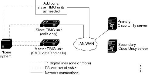
The NEC NEAX 2400 IMX phone system sends call information and MWI requests through the data link, which consists of an RS-232 serial cable between the phone system and the master TIMG unit. Voice connections are sent through the T1 digital lines (DS1 or "dry T1" digital lines only) between the phone system and the TIMG units. The TIMG units communicate with the primary and secondary servers through the LAN or WAN by using Session Initiation Protocol (SIP). Figure 2 shows the required connections.

Figure 2 Connections Between the Phone System and Cisco Unity Servers

The primary and secondary servers act in the following manner:

When the primary server is operating normally, the secondary server is inactive.

When the primary server becomes inactive, the secondary server becomes active.

When the primary server becomes active again, the secondary server becomes inactive.

Setting Up the Secondary Server for Failover

Do the following procedure to integrate the secondary server.

To Set Up the Secondary Server for Failover


Step 1 Install a secondary server with the same configuration as the primary server. For installation instructions, refer to the applicable Cisco Unity installation guide.

Step 2 On the Windows Start menu of the secondary server, click Programs > Cisco Unity > Manage Integrations. The UTIM window appears.

Step 3 On the Integration menu of the UTIM window, click New. The Telephony Integration Setup Wizard appears.

Step 4 Enter the settings to match the integration settings on the primary server.


Note We recommend not reassigning any unassigned subscribers and call handlers to the new integration, if you are asked by the wizard. Failover replication will automatically assign the correct integration.


Step 5 At the prompt to restart the Cisco Unity services, click Yes.


Note When restarting the Cisco Unity services, use the UTIM prompt instead of the Cisco Unity icon in the Windows taskbar. The taskbar icon does not restart all of the Cisco Unity services.


Step 6 After Cisco Unity restarts, on the Windows Start menu of the Cisco Unity server, click Programs > Cisco Unity > Manage Integrations. UTIM appears.

Step 7 In the left pane of the UTIM window, click the phone system integration that you created in Step 3.

Step 8 In the right pane, click Properties.

Step 9 On the Integration tab, compare the setting of the Integration ID field for the secondary server to the setting of the Integration ID field for the primary server.

Step 10 If the integration IDs of the phone system on the primary and secondary server are the same, continue to Step 16.

If the integration IDs of the phone system on the primary and secondary servers are different, on the secondary server, click Modify Integration ID.

Step 11 When cautioned that subscribers associated with the current Integration ID setting will not be automatically associated with the new Integration ID setting, click OK.

Step 12 In the Modify Integration ID dialog box, in the Enter New Integration ID field, enter the Integration ID setting for the phone system on the primary server and click OK.

Step 13 Click Save.

Step 14 At the prompt to restart the Cisco Unity services, click Yes.

Step 15 In the left pane, click the phone system integration that you created in Step 3.

Step 16 In the right pane, click the Ports tab.

Step 17 Enter the port settings to match the port settings on the primary server.


Caution In programming the phone system, do not send calls to voice messaging ports in Cisco Unity that cannot answer calls (voice messaging ports that are not set to Answer Calls). For example, if a voice messaging port is set only to Dialout MWI, do not send calls to it.

Step 18 Click Save.

Step 19 Repeat Step 16 through Step 18 for each remaining TIMG unit in the phone system integration.

Step 20 Exit UTIM.


Appendix: Documentation and Technical Assistance


Conventions

The NEC NEAX 2400 IMX Serial MCI TIMG Integration Guide for Cisco Unity 4.2 uses the following conventions.

Table 25 NEC NEAX 2400 IMX Serial MCI TIMG Integration Guide for Cisco Unity 4.2 Conventions 

Convention
Description

boldfaced text

Boldfaced text is used for:

Key and button names. (Example: Click OK.)

Information that you enter. (Example: Enter Administrator in the User Name box.)

< >

(angle brackets)

Angle brackets are used around parameters for which you supply a value. (Example: In the Command Prompt window, enter ping <IP address>.)

-

(hyphen)

Hyphens separate keys that must be pressed simultaneously. (Example: Press Ctrl-Alt-Delete.)

>

(right angle
bracket)

A right angle bracket is used to separate selections that you make:

On menus. (Example: On the Windows Start menu, click Settings > Control Panel > Phone and Modem Options.)

In the navigation bar of the Cisco Unity Administrator. (Example: Go to the System > Configuration > Settings page.)

[x]

(square brackets)

Square brackets enclose an optional element (keyword or argument). (Example: [reg-e164])

[x | y]

(vertical line)

Square brackets enclosing keywords or arguments separated by a vertical line indicate an optional choice. (Example: [transport tcp | transport udp])

{x | y}

(braces)

Braces enclosing keywords or arguments separated by a vertical line indicate a required choice. (Example: {tcp | udp})


The NEC NEAX 2400 IMX Serial MCI TIMG Integration Guide for Cisco Unity 4.2 also uses the following conventions:


Note Means reader take note. Notes contain helpful suggestions or references to material not covered in the document.


Caution Means reader be careful. In this situation, you might do something that could result in equipment damage or loss of data.

For descriptions and URLs of Cisco Unity documentation on Cisco.com, see the Documentation Guide for Cisco Unity. The document is shipped with Cisco Unity and is available at http://cisco.com/en/US/products/sw/voicesw/ps2237/products_documentation_roadmap09186a00801179df.html.

Obtaining Documentation, Obtaining Support, and Security Guidelines

For information on obtaining documentation, obtaining support, providing documentation feedback, security guidelines, and also recommended aliases and general Cisco documents, see the monthly What's New in Cisco Product Documentation, which also lists all new and revised Cisco technical documentation, at:

http://www.cisco.com/en/US/docs/general/whatsnew/whatsnew.html


[an error occurred while processing this directive]