Mitel SX-2000 ONS DTMF Integration Guide for Cisco Unity 3.1(2) and Later
Mitel SX-2000 ONS DTMF Integration

Table Of Contents

Mitel SX-2000 ONS DTMF Integration

Integration Overview

Integration Steps

Requirements

Integration Description

Integration Features

Programming the Phone System

Configuring Cisco Unity for the Integration

Testing the Integration

Integrating a Cisco Unity Failover (Secondary) Server

Requirements

Integration Description

Setting Up a Failover (Secondary) Server


Mitel SX-2000 ONS DTMF Integration


Integration Overview

Before performing the following integration steps, confirm that the Cisco Unity server is ready for the integration by completing the appropriate tasks in the Cisco Unity Installation Guide.

Integration Steps

Follow these steps to set up this integration.

1. Review the system and equipment requirements to confirm that all phone system and Cisco Unity server requirements have been met. See the "Requirements" section.

2. Program the phone system and extensions. See the "Programming the Phone System" section.

3. Configure Cisco Unity for the integration. See the "Configuring Cisco Unity for the Integration" section.

4. Test the integration. See the "Testing the Integration" section.

5. If you have a Cisco Unity failover (secondary) server, integrate the secondary server. See the "Integrating a Cisco Unity Failover (Secondary) Server" section.

Requirements

The Mitel SX-2000 integration supports configurations of the following components:

Phone System

Mitel SX-2000

Software level Lightware 30 or later

The ONS ports (on premise line voice messaging ports) in the phone system connected to the voice cards in the Cisco Unity server

The phone system ready for the integration as described in the installation guide for the phone system

Cisco Unity Server

The Dialogic D/41EPCI, D/120JCT-LS, or D/120JCT-Euro voice cards, installed

Cisco Unity installed and ready for the integration as described in the Cisco Unity Installation Guide

A system key that enables the integration and the appropriate number of voice messaging ports

Integration Description

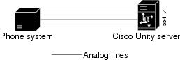
The Mitel SX-2000 phone system communicates with the Cisco Unity server by using DTMF sequences. The voice messaging lines from the phone system connect to the analog voice cards in the Cisco Unity server. Figure 1-1 shows the required connections.

Figure 1-1 Connections Between the Phone System and Cisco Unity

The phone system sends the following information with forwarded calls:

The extension of the called party

Cisco Unity uses this information to answer the call appropriately. For example, a call forwarded to Cisco Unity is answered with the personal greeting of the subscriber. If the phone system routes the call to Cisco Unity without this information, Cisco Unity answers with the opening greeting.

Integration Features

The Mitel SX-2000 integration with Cisco Unity provides the following features:

Call forward to personal greeting

When an incoming call is routed to an unanswered or busy extension, the call is forwarded to the voice mail of the subscriber. The caller then hears the personal greeting of the subscriber and can leave a message.

Message waiting indication

When a message is waiting for a subscriber, Cisco Unity notifies the phone system to activate the message waiting indicator (MWI) on the subscriber's extension (a lamp or a stutter dial tone).


Programming the Phone System

If you use programming options other than those supplied in the following procedure, the performance of the integration may be affected.

To program the phone system


Step 1 On the phone system console, go to the Main menu and click Select Forms.

Step 2 On the Select Forms screen, click Feature Access Code Assignment.

Step 3 On the Feature Access Code Assignment screen, assign the following feature access codes.

Table 1-1 Feature Access Code Assignment Settings 

Feature Access Code
Setting

Msg Waiting Activate

#51

This code must match the beginning portion of the setting of the MWI On Code field on the System > Switch page in the Cisco Unity Administrator.

Msg Waiting Deactivate

#52

This code must match the beginning portion of the setting of the MWI Off Code field on the System > Switch page in the Cisco Unity Administrator.

Call Hold - Retrieve

*1


Step 4 On the Select Forms screen, click Class of Service Options Assignment.

Step 5 On the Class of Service Options Assignment screen, create a class of service for the voice messaging ports with the following settings.

Table 1-2 Class of Service Options Assignment Settings - Ports 

Class of Service Option
Setting

Call Forwarding - Accept

Yes

COV/ONS/E&M Voice Mail Port

Yes

Disable Send Message

No

ONS Vmail - Delay Dial Tone Timer

5


Step 6 On the Class of Service Options Assignment screen, create a class of service for Cisco Unity subscribers with the following settings.

Table 1-3 Class of Service Options Assignment Settings - Subscribers 

Class of Service Option
Setting

Call Forwarding (Internal Destination)

Yes

Message Waiting

Yes (only if the Message Waiting Audible Tone Notification option is set to No)

Message Waiting Audible Tone Notification

Yes (only if the Message Waiting option is set to No)


Step 7 On the Main menu, click Single Line Set Forms.

Step 8 On the Single Line Forms screen, click Single Line Assignment.

Step 9 On the Single Line Set Assignment screen, assign an extension number to each voice messaging port.

Step 10 On the Main menu, click Station Service Set Forms.

Step 11 On the Station Service Set Forms screen, click Station Service Assignment.

Step 12 On the Station Service Assignment screen, assign each voice messaging port to the class of service created in Step 5.

Step 13 On the Main menu, click Group Forms.

Step 14 On the Group Forms screen, click Hunt Group Assignment.

Step 15 On the Hunt Group Assignment screen, create a terminal hunt group for all voice messaging ports and set the Type field to Voice Mail.

Step 16 Program each phone to forward calls to the pilot number assigned to the voice messaging ports, based on one of the following Cisco Unity call transfer types.

Table 1-4 Call Transfer Types 

Transfer Type
Usage

Release transfer
(blind transfer)

Program the phone to forward calls to the pilot number when:

The extension is busy

The call is not answered

Supervised transfer

Program the phone to forward calls to the pilot number only when the call is not answered. Confirm that call forwarding is disabled when the extension is busy.


Configuring Cisco Unity for the Integration

After ensuring that the Cisco Unity server is ready for the integration by completing the appropriate tasks in the Cisco Unity Installation Guide, perform the following procedures to confirm that the integration is enabled and to enter the port settings.

To confirm that the integration is enabled


Step 1 On the Cisco Unity server, go to the Cisco Unity Administrator by doing one of the following:

In Internet Explorer, go to http://<server name>/web/sa.

Double-click the desktop shortcut to the Cisco Unity Administrator.

Step 2 Go to System > Licensing > Licensed Features.

Step 3 In the Integration field, confirm that the setting is Analog for a single phone system integration or Multiple Integrations for a dual phone system integration.

Step 4 If the setting is not Analog or Multiple Integrations, contact your sales representative for the necessary system key.

Step 5 Go to System > Switch. Confirm that the settings match those in the following table. If the settings are incorrect, integration features may not be enabled.

Table 1-5 Switch Settings 

Switch Parameter
Required Setting

Manufacturer

Mitel

Model

SX-2000

Switch PBX Software Version

Lightware 30

Integration

Analog


Step 6 If necessary, edit the codes that turn message waiting indication on and off. The MWI codes are located in the Active Switch Setting area at the top of the Switch Settings page.

Step 7 Click the Save icon.


To enter port settings


Step 1 In the Cisco Unity Administrator, go to System > Ports.

Step 2 Select a port in the table.

Step 3 Indicate the settings for the port.

For a hunt group, use the first voice-messaging ports for incoming calls and the last ports to dial out. This helps minimize the possibility of a collision, in which an incoming call arrives on a port at the same time that Cisco Unity takes the port off-hook to dial out.

Step 4 Type the extension for the port.

Step 5 Repeat Steps 2 through 4 for the remaining ports.

Step 6 Click the Save icon.

Step 7 For the settings to take effect, exit and restart the Cisco Unity software. For more information, see Appendix A, "Exiting and Starting the Cisco Unity Software and Server."


Testing the Integration

To test whether Cisco Unity and the phone system are integrated correctly, perform the procedures in the order listed.

If any of the steps indicates a failure, see the following documentation as appropriate:

The installation guide for the phone system

Cisco Unity Troubleshooting Guide

This integration guide

To set up the test configuration


Step 1 Set up two test extensions (Phone 1 and Phone 2) on the same phone system that Cisco Unity is connected to.

Step 2 Set Phone 1 to forward calls to the Cisco Unity pilot number when calls are not answered.

Step 3 In the Cisco Unity Administrator, go to Subscribers > Subscribers > Profile.

If Example Subscriber is not displayed, click the Find icon (the magnifying glass) in the title bar, then click Find, and select Example Subscriber in the list that appears.

Step 4 In the Extension field, enter the extension of Phone 1.

Step 5 Click the Save icon.

Step 6 In the navigation bar, click Call Transfer to go to Subscribers > Subscribers > Call Transfer for Example Subscriber.

For more information on transfer settings, refer to the "Subscriber Template Call Transfer Settings" section in the Help for the Cisco Unity Administrator.

Step 7 Under Transfer Incoming Calls, click Yes, Ring Subscriber's Extension, and confirm that the extension number is for Phone 1.

Step 8 Under Transfer Type, click Release to Switch.

Step 9 Click the Save icon.

Step 10 In the navigation bar, click Messages to go to Subscribers > Subscribers > Messages for Example Subscriber.

Step 11 Under Message Waiting Indicators (MWIs), check Use MWI for Message Notification.

Step 12 In the Extension field, enter x.

Step 13 Click the Save icon.

Step 14 Open the Status Monitor by doing one of the following:

In Internet Explorer, go to http://<server name>/web/sm.

Double-click the desktop shortcut to the Status Monitor.

In the Windows systray, right-click the Cisco Unity icon and click Status Monitor.


To test an external call with release transfer


Step 1 From Phone 2, enter the access code necessary to get an outside line, then enter the number outside callers use to dial directly to Cisco Unity.

Step 2 On the Status Monitor, note the port that handles this call.

Step 3 When you hear the opening greeting, enter the extension for Phone 1. Hearing the opening greeting means that the port is configured correctly.

Step 4 Confirm that Phone 1 rings and that you hear a ringback tone on Phone 2. Hearing a ringback tone means that Cisco Unity released the call and transferred it to Phone 1.

Step 5 Do not answer Phone 1, and confirm that the state of the port handling the call changes to "Idle." This state means that release transfer succeeds.

Step 6 Confirm that, after the number of rings that the phone system is set to wait, the call is forwarded to Cisco Unity and that you hear the greeting for Example Subscriber. Hearing the greeting means that the phone system forwarded the unanswered call and the call-forward information to Cisco Unity, which correctly interpreted the information.

Step 7 On the Status Monitor, note the port that handles this call.

Step 8 Leave a message for Example Subscriber and hang up Phone 2.

Step 9 On the Status Monitor, confirm that the state of the port handling the call changes to "Idle." This state means that the port was successfully released when the call ended.

Step 10 Confirm that the MWI on Phone 1 is activated. The activated MWI means that the phone system and Cisco Unity are successfully integrated for turning on MWIs.


To test an internal call with release transfer


Step 1 From Phone 1, enter the internal pilot number for Cisco Unity.

Step 2 Dial the Cisco Unity phone number.

Step 3 When you hear the opening greeting, press *.

Step 4 Enter the ID (extension number) for the Example Subscriber, then press *.

Step 5 Confirm that you hear the recorded voice name for Example Subscriber. Hearing the voice name means that Cisco Unity correctly identified the subscriber by the extension.

Step 6 When asked whether you want to listen to your messages, press 1.

Step 7 After listening to the message, press 3 to delete the message.

Step 8 Confirm that the MWI on Phone 1 is deactivated. The deactivated MWI means that the phone system and Cisco Unity are successfully integrated for turning off MWIs.

Step 9 Hang up Phone 1.

Step 10 On the Status Monitor, confirm that the state of the port handling the call changes to "Idle." This state means that the port was successfully released when the call ended.


To set up supervised transfer on Cisco Unity


Step 1 In the Cisco Unity Administrator, go to Subscribers > Subscribers > Call Transfer.

If Example Subscriber is not displayed, click the Find icon (the magnifying glass) in the title bar, then click Find, and select Example Subscriber in the list that appears.

For more information on transfer settings, refer to the "Subscriber Template Call Transfer Settings" section in the Help for the Cisco Unity Administrator.

Step 2 Under Transfer Type, click Supervise Transfer.

Step 3 Set the Rings to Wait For field to 3.

Step 4 Click the Save icon.


To test supervised transfer


Step 1 From Phone 2, enter the access code necessary to get an outside line, then enter the number outside callers use to dial directly to Cisco Unity.

Step 2 On the Status Monitor, note the port that handles this call.

Step 3 When you hear the opening greeting, enter the extension for Phone 1. Hearing the opening greeting means that the port is configured correctly.

Step 4 Confirm that Phone 1 rings and that you do not hear a ringback tone on Phone 2. Instead, you should hear the indication your phone system uses to mean that the call is on hold (for example, music or beeps).

Step 5 Do not answer Phone 1, and confirm that the state of the port handling the call remains "Busy." This state and hearing an indication that you are on hold mean that Cisco Unity is supervising the transfer.

Step 6 Confirm that, after three rings, you hear the greeting for Example Subscriber. Hearing the greeting means that Cisco Unity successfully recalled the supervised-transfer call.

Step 7 During the greeting, hang up Phone 2.

Step 8 On the Status Monitor, confirm that the state of the port handling the call changes to "Idle." This state means that the port was successfully released when the call ended.


To return Example Subscriber to the default settings


Step 1 In the Cisco Unity Administrator, go to Subscribers > Subscribers > Call Transfer.

If Example Subscriber is not displayed, click the Find icon (the magnifying glass) in the title bar, then click Find, and select Example Subscriber in the list that appears.

Step 2 Under Transfer Incoming Calls, click No (Send Directly to Subscriber's Greeting).

Step 3 In the navigation bar, click Profile to go to Subscribers > Subscribers > Profile.

Step 4 In the Extension field, enter 99990.

Step 5 Click the Save icon.

Step 6 In the navigation bar, click Messages to go to Subscribers > Subscribers > Messages for Example Subscriber.

Step 7 Under Message Waiting Indicators (MWIs), uncheck Use MWI for Message Notification.

Step 8 Click the Save icon.


Integrating a Cisco Unity Failover (Secondary) Server

A Cisco Unity failover server is a secondary (or backup) server that provides voice messaging services if the primary Cisco Unity server becomes inactive. For information on installing a secondary server, refer to the Cisco Unity Installation Guide.

Requirements

The following components are required to integrate a Cisco Unity secondary server:

One secondary Cisco Unity server for each primary server installed and ready for the integration, as described in the Cisco Unity Installation Guide and earlier in this integration guide.

The appropriate cable configuration for each analog voice messaging port to simultaneously connect the phone system to the corresponding ports on both the primary and the secondary servers. For example, connect port 1 on the phone system with both port 1 on the primary server and port 1 on the secondary server.

A system key that enables the integration, the appropriate number of voice messaging ports, and the secondary server.

Integration Description

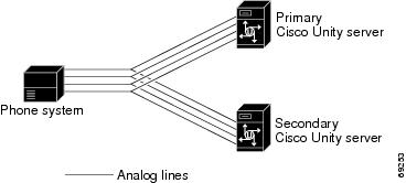
The phone system communicates with both the primary and secondary servers through the connecting cables. Figure 1-2 shows the required connections.

Figure 1-2 Connections Between the Phone System and Cisco Unity Servers

The primary and secondary servers act in the following manner:

When the primary server is operating normally, the secondary server is inactive.

When the primary server becomes inactive, the secondary server becomes active.

When the primary server becomes active again, the secondary server becomes inactive.

Setting Up a Failover (Secondary) Server

Do the following procedure to integrate a Cisco Unity secondary server.

To set up a failover (secondary) server


Step 1 Install a secondary server with the same configuration as the primary server. For installation instructions, refer to the Cisco Unity Installation Guide.

Step 2 Make all voice connections from the phone system to the corresponding ports on both the primary server and the secondary server. For example, connect port 1 from the phone system with port 1 on both the primary and the secondary servers.

Step 3 In the Cisco Unity Administrator of the secondary server, enter the settings on the System > Ports page to match the port settings on the primary server.

Step 4 If the automatic failover that occurs when the secondary server receives a call is disabled, skip the remaining steps.

If the automatic failover that occurs when the secondary server receives a call is enabled (the default), on the Windows Start menu of the Cisco Unity server, click Programs > Unity >Edit Switch Utility.

Step 5 In the Switch Configuration Editor dialog box, click the Edit This Switch Configuration button.

Step 6 In the Switch Configuration dialog box, click the Incoming Calls tab.

Step 7 In the Call Rings field, enter 3 and click OK.

Step 8 Click Exit.

Step 9 For the setting to take effect, exit and restart the Cisco Unity software. For more information, see Appendix A, "Exiting and Starting the Cisco Unity Software and Server."


No changes to the hunt group programming on the phone system are necessary.