Feedback Feedback
|
Table Of Contents
Nortel Meridian 1/PBXLink Integration Guide for Cisco Unity 3.1
Planning How the Voice Messaging Ports Will Be Used by Cisco Unity
Preparing for Programming the Phone System
Programming the Nortel Meridian/PBXLink Phone System
Configuring Cisco Unity for the Integration
Integrating a Secondary Server for Cisco Unity Failover
Setting Up the Secondary Server for Failover
Dual Phone System Integration Overview
Integration Steps When No Phone Systems Are Installed
Integration Steps When a Circuit-Switched Phone System Is Already Installed
Integration Steps When Cisco CallManager Is Already Installed
Changing Cisco Unity Administrator Settings
To specify switch settings for Cisco CallManager
Changing the Number of Installed Ports
Appendix: Remapping Extension NumbersSetting Up Cisco Unity to Remap Extension Numbers
Appendix: Assigning Dialogic Ports for a Dual Phone System Integration
Appendix: Documentation and Technical AssistanceObtaining Technical Assistance
Cisco Technical Support Website
Obtaining Additional Publications and Information
Nortel Meridian 1/PBXLink Integration Guide for Cisco Unity 3.1
Revised June 1, 2004
This document provides instructions for integrating the phone system with the Cisco Unity voice messaging system.
Integration Tasks
Before performing the following tasks to integrate Cisco Unity with the Nortel Meridian/PBXLink phone system, confirm that the Cisco Unity server is ready for the integration by completing the appropriate tasks in the Cisco Unity Installation Guide.
Integration Steps
Follow these steps to set up this integration.
1.
Review the system and equipment requirements to confirm that all phone system and Cisco Unity server requirements have been met. See the "Requirements" section.
2.
3.
4.
5.
6.
7.
Requirements
The Nortel Meridian/PBXLink integration supports configurations of the following components:
Phone System
•
Table 1 Required Option Packages
EES
10
MSB
17
DDSP
19
MWC
46
DSET
88
CPND
95
ARIE
170
•
•
•
–
–
–
–
–
–
–
•
•
Cisco Unity Server
•
•
•
•
Integration Description
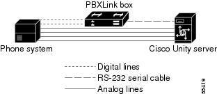
The Nortel Meridian/PBXLink integration uses one or more PBXLink boxes that each emulate up to two Nortel M2616 digital phones. The PBXLink is connected to the phone system with digital phone lines and connected to the Cisco Unity server with an RS-232 serial cable. The voice messaging lines from the phone system connect to the analog voice cards in the Cisco Unity server.
The PBXLink box receives the following call information from the phone system:
•
•
•
The PBXLink box formats this information as a Simplified Message Desk Interface (SMDI) packet and sends the packet to Cisco Unity through the RS-232 serial cable.
Cisco Unity uses this information to answer the call appropriately. For example, a call forwarded to Cisco Unity is answered with the personal greeting of the subscriber. If the phone system routes the call to Cisco Unity without this information, Cisco Unity answers with the opening greeting.
The PBXLink box also activates or deactivates message waiting indicators (MWIs) after receiving a command from Cisco Unity.
For additional information on the PBXLink box, refer to the PBXLink documentation, which is available from the manufacturer.
Configuration for 24 or Fewer Ports
Nortel Meridian/PBXLink integrations with 24 or fewer ports can use one of the following configurations (others are possible):
•
•
Configuration for 25 to 48 Ports
Nortel Meridian/PBXLink integrations with 25 to 48 ports can use the following configuration (others are possible):
•
Configuration for 49 to 72 Ports
Nortel Meridian/PBXLink integrations with 49 to 72 ports can use one of the following configurations (others are possible):
•
•
•
It is not possible to use a single PBXLink-48 box with Port A set to both calls and MWIs and Port B set for calls only. In this configuration, Port B is disabled.
PBXLink Box Connections
A single PBXLink box is connected to the phone system with a digital phone line and connected to the Cisco Unity server with an RS-232 serial cable. The voice messaging lines from the phone system connect to the analog voice cards in the Cisco Unity server. Figure 1 shows the required connections.
Figure 1 Serial Connection Between a Single PBXLink Box and Cisco Unity
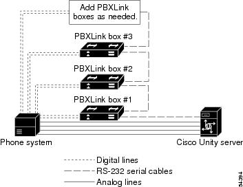
Multiple PBXLink boxes are connected to the Cisco Unity server by using an RS-232 cable to connect the SMDI port from the last PBXLink box to the Management port of the first PBXLink box. Another RS-232 cable is then used to connect the SMDI port of the first PBXLink box to the Cisco Unity server. The voice messaging lines from the phone system connect to the analog voice cards in the Cisco Unity server. Figure 2 shows the required connections.
Figure 2 Serial Connections Between Multiple PBXLink Boxes and Cisco Unity
Integration Features
The Nortel Meridian/PBXLink integration with Cisco Unity provides the following features.
Planning How the Voice Messaging Ports Will Be Used by Cisco Unity
Before programming the phone system, you need to plan how the voice messaging ports will be used by Cisco Unity. The following considerations will affect the programming for the phone system (for example, setting up the hunt group or call forwarding for the voice messaging ports):
•
•
•
The Number of Voice Messaging Ports to Install
The number of voice messaging ports to install depends on numerous factors, including:
•
•
•
•
•
•
•
•
It is best to install only the number of voice messaging ports that are needed so that system resources are not allocated to unused ports.
The Number of Voice Messaging Ports That Will Answer Calls
The calls that the voice messaging ports answer can be incoming calls from unidentified callers or from subscribers. Typically, these voice messaging ports are the busiest. They also have the lowest port numbers for the phone system. As a general guideline, assign approximately 75 percent of the voice messaging ports to answer calls.
You can set voice messaging ports to both answer calls and to dial out (for example, to set MWIs).
The Number of Voice Messaging Ports That Will Only Dial Out, and Not Answer Calls
Ports that will only dial out and will not answer calls can do one or more of the following:
•
•
•
•
Typically, these voice messaging ports are the least busy ports. They also have the highest port numbers for the phone system. As a general guideline, assign approximately 25 percent of the voice messaging ports to dial out.
Caution
Preparing for Programming the Phone System
Record your decisions about the voice messaging ports to guide you in programming the phone system.
Programming the Nortel Meridian/PBXLink Phone System
If you use programming options other than those supplied in the following procedure, the performance of the integration may be affected.
If you want to remap extension numbers (for example, when multiple subscribers use a single phone, or when multiple extension numbers on a single phone should go to a single subscriber greeting), see "Appendix: Remapping Extension Numbers" section.
Caution
To program the Nortel Meridian/PBXLink phone system
Step 1
Step 2
Step 3
Step 4
Table 3 Calling Party Display Options
REQ
CHG
TYPE
CPND
CUST
<customer number>
RESN
YES
CFWD
CFWD
CFNA
CFNA
HUNT
HUNT
XFER
T
AAA
A
Step 5
Step 6
If you set up more than 24 voice messaging ports, it is recommended that you balance the load among the PBXLink boxes. You can balance the load by enabling digital line keys for one PBXLink box to monitor odd-numbered ports (1, 3, 5, and so on), while enabling digital line keys on the other PBXLink box to monitor even-numbered ports (2, 4, 6, and so on). For details, see the "To set up the port LTNs for two PBXLink digital ports" section.
Step 7
Perform one of the following procedures, depending on the number of voice messaging ports in the Cisco Unity server. If Cisco Unity has more than 30 voice messaging ports, it is recommended that you set up an ACD hunt group as described in the "To set up an ACD hunt group for more than 30 ports" section.
To set up a hunt group for up to 30 ports
Step 1
Step 2
Step 3
Step 4
Table 7 Example of 30-Port Hunt Group
Port 1
HUNT
Port 2
Port 2
HUNT
Port 3
Port 3
HUNT
Port 4
.
.
.<additional ports>
Port 29
HUNT
Port 30
Port 30
HUNT
Port 1
To set up an ACD hunt group for more than 30 ports
Step 1
Step 2
Step 3
Step 4
Step 5
Step 6
Step 7
Step 8
Setting up the PBXLink Box
When setting up the PBXLink box, you can access the configuration menus through:
•
•
To Update the PBXLink Box Firmware
Step 1
Note
Step 2
Step 3
Step 4
Step 5
Step 6
•
•
Step 7
Step 8
Step 9
a.
b.
c.
d.
e.
Step 10
Step 11
Step 12
Step 13
Note
Step 14
Step 15
Step 16
Step 17
Step 18
Step 19
Step 20
Step 21
To set up the PBXLink box
Step 1
Step 2
Step 3
Step 4
Step 5
Step 6
Step 7
Step 8
Table 9 Port Configuration Settings
Calls Only
The port handles only calls.
MWI Only
The port handles only MWIs.
Step 9
Step 10
Step 11
Table 10 Call Forward Display Options
CFWD
•
•
CFNA
CFNA
HUNT
HUNT
If the system has two or more PBXLink digital ports, it is recommended that you balance the load among the PBXLink boxes by setting up the Port LTNs for random operation. Depending on the number of PBXLink digital ports your system uses, perform the appropriate procedure that follows.
To set up the port LTNs for two PBXLink digital ports
This procedure sets up the port LTNs for every second voice messaging port.
Step 1
Step 2
Step 3
Table 11 Random LTN Settings for Odd-Numbered Ports
0
0001
1
0003
2
0005
.
.
.<the remaining odd-numbered voice messaging ports>
Step 4
Step 5
Table 12 Random LTN Settings for Even-Numbered Ports
0
0002
1
0004
2
0006
.
.
.<the remaining even-numbered voice messaging ports>
Step 6
To set up the port LTNs for three PBXLink digital ports
This procedure sets up the port LTNs for every third voice messaging port.
Step 1
Step 2
Step 3
Table 13 Random LTN Settings for the First Set of Ports
0
0001
1
0004
2
0007
.
.
.<the remaining voice messaging ports in the first set>
Step 4
Step 5
Table 14 Random LTN Settings for the Second Set of Ports
0
0002
1
0005
2
0008
.
.
.<the remaining voice messaging ports in the second set>
Step 6
Step 7
Table 15 Random LTN Settings for the Third Set of Ports
0
0003
1
0006
2
0009
.
.
.<the remaining voice messaging ports in the third set>
Step 8
Configuring Cisco Unity for the Integration
After ensuring that the Cisco Unity server is ready for the integration by completing the appropriate tasks in the Cisco Unity Installation Guide, perform the following procedures to confirm that the integration is enabled and to enter the port settings.
To confirm that the integration is enabled
Step 1
•
•
Step 2
Step 3
Step 4
Step 5
Table 16 Switch Settings
Manufacturer
Nortel
Model
Meridian-1
Switch PBX Software Version
All
Integration
Serial
Step 6
To enter port settings
Step 1
Step 2
Step 3
When setting up the hunt group, use the first voice messaging ports for incoming calls and the last ports to dial out. This helps minimize the possibility of a collision, in which an incoming call arrives on a port at the same time that Cisco Unity takes the port off-hook to dial out.
Step 4
Step 5
Step 6
Step 7
Testing the Integration
To test whether Cisco Unity and the phone system are integrated correctly, do the procedures in the order listed.
If any of the steps indicates a failure, refer to the following documentation as applicable:
•
•
•
To Set Up the Test Configuration
Step 1
Step 2
Step 3
If Example Subscriber is not displayed, click the Find icon (the magnifying glass) in the title bar, then click Find, and select Example Subscriber in the list that appears.
Step 4
Step 5
Step 6
For more information on transfer settings, refer to the "Subscriber Template Call Transfer Settings" section in the online Help for the Cisco Unity Administrator.
Step 7
Step 8
Step 9
Step 10
Step 11
Step 12
Step 13
Step 14
•
•
•
To Test an External Call with Release Transfer
Step 1
Step 2
Step 3
Step 4
Step 5
Step 6
Step 7
Step 8
Step 9
Step 10
To Test an Internal Call with Release Transfer
Step 1
Step 2
Step 3
Step 4
Step 5
Step 6
Step 7
Step 8
To Set Up Supervised Transfer on Cisco Unity
Step 1
If Example Subscriber is not displayed, click the Find icon (the magnifying glass) in the title bar, then click Find, and select Example Subscriber in the list that appears.
For more information on transfer settings, refer to the "Subscriber Template Call Transfer Settings" section in the online Help for the Cisco Unity Administrator.
Step 2
Step 3
Step 4
To Test Supervised Transfer
Step 1
Step 2
Step 3
Step 4
Step 5
Step 6
Step 7
Step 8
To Return Example Subscriber to the Default Settings
Step 1
If Example Subscriber is not displayed, click the Find icon (the magnifying glass) in the title bar, then click Find, and select Example Subscriber in the list that appears.
Step 2
Step 3
Step 4
Step 5
Step 6
Step 7
Step 8
Integrating a Secondary Server for Cisco Unity Failover
A Cisco Unity failover server is a secondary (or backup) server that provides voice messaging services if the primary Cisco Unity server becomes inactive. For information on installing a secondary server, refer to the Cisco Unity Installation Guide, available at http://www.cisco.com/en/US/products/sw/voicesw/ps2237/prod_installation_guides_list.html.
For information on failover, refer to the Cisco Unity Failover Guide, available at http://www.cisco.com/univercd/cc/td/doc/product/voice/c_unity/unity31/fail/fail31/index.htm.
Note
Requirements
The following components are required to integrate a secondary Cisco Unity server:
Phone System
•
•
•
Cisco Unity Server
•
•
•
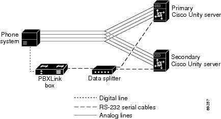
Integration Description
The phone system uses PBXLink boxes to send call information to the two Cisco Unity servers. The analog voice messaging lines from the phone system provide voice connectivity to the Cisco Unity servers. Figure 3 shows the required connections.
Figure 3 Connections Between the Phone System and Cisco Unity Servers
The primary and secondary servers act in the following manner:
•
•
•
Setting Up the Secondary Server for Failover
Do the following procedure to integrate the Cisco Unity secondary server.
To Set Up the Secondary Server for Failover
Step 1
Step 2
Step 3
Step 4
Step 5
Step 6
Caution
Step 7
If the automatic failover that occurs when the secondary server receives a call is enabled (the default), on the Windows Start menu of the Cisco Unity server, click Programs > Cisco Unity > Edit Switch Utility.
Step 8
Step 9
Step 10
Step 11
Step 12
No changes to the hunt group programming on the phone system are necessary.
Dual Phone System Integration
Cisco Unity can be integrated with one each of the following phone systems at the same time:
•
•
All extensions for subscribers and call handlers must be unique regardless of which phone system a subscriber (or call handler) uses. To transfer calls from one phone system to the other, Cisco Unity must dial the same access codes that a subscriber dials when calling someone on the other phone system.
Dual Phone System Integration Overview
Before doing the following integration steps, confirm that theCisco Unity server is ready for the integration by completing the applicable tasks in the Cisco Unity Installation Guide.
Integration Steps When No Phone Systems Are Installed
Follow these steps to set up the dual phone system integration when no phone systems are installed.
1.
2.
3.
4.
5.
Integration Steps When a Circuit-Switched Phone System Is Already Installed
Follow these steps to set up the dual phone system integration when the circuit-switched phone system is already installed and Cisco CallManager is being newly installed.
1.
2.
3.
Integration Steps When Cisco CallManager Is Already Installed
Follow these steps to set up the dual phone system integration when Cisco CallManager is already installed and a circuit-switched phone system is being newly installed.
1.
2.
3.
4.
5.
Requirements
The dual phone system integration supports configurations of the following components:
•
•
•
•
Changing Cisco Unity Administrator Settings
After Cisco Unity is installed and the phone systems have been separately integrated, you need to adjust settings on pages in the Cisco Unity Administrator so that Cisco Unity can work with both phone systems.
Follow these steps to set up the dual phone system integration.
1.
Caution
2.
3.
4.
5.
Caution
To Specify Switch Settings for the Circuit-Switched Phone System
Step 1
Step 2
The access code is the same number that subscribers on the circuit-switched phone system dial to reach someone on the Cisco CallManager system.
Step 3
Step 4
To specify switch settings for Cisco CallManager
Step 1
Step 2
Table 17 Switch Settings
Manufacturer
Cisco
Model
CallManager
Switch PBX software version
3.01 or later
Integration
TAPI
Step 3
Step 4
The access code is the same number that subscribers on Cisco CallManager dial to reach someone on the circuit-switched phone system.
Step 5
To Modify Voice Port Settings
Step 1
Step 2
Caution
Step 3
Step 4
Step 5
Step 6
Caution
To Select Which Phone System Subscribers and Call Handlers Use
For existing subscriber templates, subscriber accounts, and call handlers, Cisco Unity uses the circuit-switched phone system as its default. Therefore, during the initial setup of the dual phone integration, you will modify only those pages that will be using Cisco CallManager. Note that changes made to subscriber templates do not affect existing subscriber accounts.
Step 1
•
•
•
Step 2
Step 3
Caution
To Select Which Phone System Cisco Unity Uses for Message Notification
If subscribers use message notification, you can select which phone system Cisco Unity dials out on when notifying subscribers of new messages. Note that changes made to subscriber templates do not affect existing subscribers.
Step 1
•
•
Step 2
Cisco Unity uses as the default the phone system specified on the Profile page of the subscriber template.
Step 3
Caution
Changing the Number of Installed Ports
After the dual phone system integration is set up, if you need to add or remove voice cards or uninstall voice card software, follow these steps:
1.
2.
3.
4.
If you completely remove the circuit-switched phone system, you must adjust the port assignments for Cisco CallManager on the System > Ports page, after the voice cards and voice card software used in the integration with the circuit-switched phone system have been removed.
To Remove the Existing TSP
Step 1
Step 2
Step 3
Step 4
Note
Step 5
Step 6
Step 7
To Reinstall the TSP
Step 1
Step 2
Step 3
Step 4
Step 5
Step 6
Step 7
Step 8
Step 9
Step 10
Appendix: Remapping Extension Numbers
About the Remapping Feature
The extension remapping feature lets you convert to the extensions of your choice the calling numbers and forwarding numbers of calls handled by Cisco Unity. This feature is useful, for example, when the phone system cannot map multiple extension numbers on a subscriber phone to a single Inbox.
Remapping can change one or both of the following extension numbers in a call:
•
•
Setting Up Cisco Unity to Remap Extension Numbers
This section includes a procedure for enabling the remapping feature. You can create multiple files in either or both of two directories:
•
•
When you create remapping instructions in a .exm file in a directory, Cisco Unity remaps only the type of extension number that the directory is named for. For example, if you want to remap only the extensions that Cisco Unity provides with calls it forwards, you enter the instructions in a .exm file in the Forwarding directory; in this circumstance, the Calling directory needs no .exm file.
In each directory, you can have several .exm files with different file names but with the same .exm extension. This helps you to organize the remapping information. For example, you could create two files in a directory: Ports_1-12.exm and Ports_13-24.exm. Cisco Unity reads all files that have the .exm extension in these directories.
To Remap Extension Numbers
Step 1
Step 2
Step 3
For an example, open the file Sample.txt in the CommServer\IntLib\ExtensionMapping directory.
Step 4
A .exm file can have only one [Range] section.
Step 5
For example, you might enter:
ports=1,2,5-34
Step 6
A .exm file can have only one [Number Mappings] section.
Step 7
See the remapping rule examples in the following "Syntax and Examples" section. The rule format is:
<original number>, <new number>
The rules cannot include spaces between digits. However, the numbers must be separated by a comma and a single space. Wildcard characters cannot appear at the beginning of a number.
Step 8
Step 9
Step 10
Step 11
Step 12
Syntax and Examples
Table 18 shows the wildcard characters you can use in the .exm files.
Table 18 Wildcard Characters
*
Matches zero or more digits.
?
Matches exactly one digit. Use ? as a placeholder for a single digit.
Table 19 gives examples for the syntax and results of rules in the .exm files.
Cisco Unity executes rules in the order they appear in the .exm file. For example, the .exm file might contain the following rules:
1234, 1189
3189, 1189
4189, 1189
123?, 8891The extension 1234 would be remapped to 1189 while extensions 1233 and 1235 would be remapped to 8891, because the rule mapping 1234 appears earlier.
An .exm file might contain the following:
[Range]
ports=1,2,5-34
[Number Mappings]
2189, 1189
3189, 1189
4189, 1189
8???, 9???
Appendix: Assigning Dialogic Ports for a Dual Phone System Integration
In a dual phone system integration, Cisco Unity assigns a voice messaging port to the traditional, circuit-switched phone system for every port available on the installed voice cards before assigning voice messaging ports to Cisco CallManager. The result is that Cisco Unity may not have enough voice messaging ports remaining to assign to Cisco CallManager.
The maximum number of voice messaging ports are assigned to the circuit-switched phone system regardless of the settings on the Ports page in the System Administrator.
For example, a dual phone system integration might have the following configuration:
•
•
•
•
Even so, Ports 1 through 4 (the total voice card ports) will be assigned to the circuit-switched phone system, and Ports 5 through 6 will be assigned to Cisco CallManager.
If you want to assign fewer than the total number of voice card ports to the circuit-switched phone system, you must first set the Port assignments on the Ports page of the System Administrator, then do the following procedure.
To Set the Port Assignments in the Registry
Step 1
Step 2
Caution
Step 3
Step 4
You will find several subkeys with this name.
Step 5
Step 6
Step 7
Step 8
Step 9
Step 10
Step 11
Step 12
Step 13
Step 14
Step 15
Appendix: Documentation and Technical Assistance
Conventions
The Nortel Meridian 1/PBXLink Integration Guide for Cisco Unity 3.1 uses the following conventions.
The Nortel Meridian 1/PBXLink Integration Guide for Cisco Unity 3.1 also uses the following conventions:
Note
Caution
Cisco Unity Documentation
For descriptions and URLs of Cisco Unity documentation on Cisco.com, refer to About Cisco Unity Documentation. The document is shipped with Cisco Unity and is available at http://www.cisco.com/univercd/cc/td/doc/product/voice/c_unity/about/aboutdoc.htm.
Obtaining Documentation
Cisco documentation and additional literature are available on Cisco.com. Cisco also provides several ways to obtain technical assistance and other technical resources. These sections explain how to obtain technical information from Cisco Systems.
Cisco.com
You can access the most current Cisco documentation on the World Wide Web at this URL:
http://www.cisco.com/univercd/home/home.htm
You can access the Cisco website at this URL:
International Cisco websites can be accessed from this URL:
http://www.cisco.com/public/countries_languages.shtml
Ordering Documentation
You can find instructions for ordering documentation at this URL:
http://www.cisco.com/univercd/cc/td/doc/es_inpck/pdi.htm
You can order Cisco documentation in these ways:
•
http://www.cisco.com/en/US/partner/ordering/index.shtml
•
Documentation Feedback
You can submit e-mail comments about technical documentation to bug-doc@cisco.com.
You can submit comments by using the response card (if present) behind the front cover of your document or by writing to the following address:
Cisco Systems
Attn: Customer Document Ordering
170 West Tasman Drive
San Jose, CA 95134-9883We appreciate your comments.
Obtaining Technical Assistance
For all customers, partners, resellers, and distributors who hold valid Cisco service contracts, the Cisco Technical Assistance Center (TAC) provides 24-hour-a-day, award-winning technical support services, online and over the phone. Cisco.com features the Cisco Technical Support website as an online starting point for technical assistance. If you do not hold a valid Cisco service contract, please contact your reseller.
Cisco Technical Support Website
The Cisco Technical Support website provides online documents and tools for troubleshooting and resolving technical issues with Cisco products and technologies. The Cisco Technical Support website is available 24 hours a day, 365 days a year. The Cisco Technical Support website is located at this URL:
Accessing all the tools on the Cisco Technical Support website requires a Cisco.com user ID and password. If you have a valid service contract but do not have a login ID or password, register at this URL:
http://tools.cisco.com/RPF/register/register.do
Opening a TAC Case
Using the online TAC Case Open Tool is the fastest way to open P3 and P4 cases. (P3 and P4 cases are those in which your network is minimally impaired or for which you require product information.) After you describe your situation, the TAC Case Open Tool automatically recommends resources for an immediate solution. If your issue is not resolved using the recommended resources, your case will be assigned to a Cisco TAC engineer. The online TAC Case Open Tool is located at this URL:
http://www.cisco.com/tac/caseopen
For P1 or P2 cases (P1 and P2 cases are those in which your production network is down or severely degraded) or if you do not have Internet access, contact Cisco TAC by telephone. Cisco TAC engineers are assigned immediately to P1 and P2 cases to help keep your business operations running smoothly.
To open a case by telephone, use one of the following numbers:
Asia-Pacific: +61 2 8446 7411 (Australia: 1 800 805 227)
EMEA: +32 2 704 55 55
USA: 1 800 553-2447For a complete listing of Cisco TAC contacts, go to this URL:
http://www.cisco.com/warp/public/687/Directory/DirTAC.shtml
TAC Case Priority Definitions
To ensure that all cases are reported in a standard format, Cisco has established case priority definitions.
Priority 1 (P1)—Your network is "down" or there is a critical impact to your business operations. You and Cisco will commit all necessary resources around the clock to resolve the situation.
Priority 2 (P2)—Operation of an existing network is severely degraded, or significant aspects of your business operation are negatively affected by inadequate performance of Cisco products. You and Cisco will commit full-time resources during normal business hours to resolve the situation.
Priority 3 (P3)—Operational performance of your network is impaired, but most business operations remain functional. You and Cisco will commit resources during normal business hours to restore service to satisfactory levels.
Priority 4 (P4)—You require information or assistance with Cisco product capabilities, installation, or configuration. There is little or no effect on your business operations.
Obtaining Additional Publications and Information
Information about Cisco products, technologies, and network solutions is available from various online and printed sources.
•
http://www.cisco.com/go/marketplace/
•
http://cisco.com/univercd/cc/td/doc/pcat/
•
•
•
http://www.cisco.com/go/iqmagazine
•
•
http://www.cisco.com/en/US/learning/index.html
Copyright © 2004 Cisco Systems, Inc. All rights reserved.