[an error occurred while processing this directive]

Cisco Unity

Matra 6500 DTMF Integration Guide for Cisco Unity 3.1

 Feedback

Table Of Contents

Matra 6500 DTMF Integration Guide for Cisco Unity 3.1

Integration Tasks

Integration Steps

Requirements

Integration Description

Integration Features

Programming the Matra 6500 Phone System

Setting Up Cisco Unity Call Handlers

Configuring Cisco Unity for the Integration

Testing the Integration

Integrating a Secondary Server for Cisco Unity Failover

Requirements

Integration Description

Setting Up a Secondary Server for Failover


Dual Phone System Integration

Dual Phone System Integration Overview

Integration Steps When No Phone Systems Are Installed

Integration Steps When a Circuit-Switched Phone System Is Already Installed

Integration Steps When Cisco CallManager Is Already Installed

Requirements

Changing Cisco Unity Administrator Settings

Changing the Number of Installed Ports


Remapping Extension Numbers

The Remapping Feature

Setting Up Cisco Unity to Remap Extension Numbers

Syntax and Examples


Assigning Dialogic Ports for a Dual Phone System Integration


Documentation and Technical Assistance

Conventions

Cisco Unity Documentation

Obtaining Documentation

World Wide Web

Documentation CD-ROM

Ordering Documentation

Documentation Feedback

Obtaining Technical Assistance

Cisco.com

Technical Assistance Center

Cisco TAC Web Site

Cisco TAC Escalation Center


Matra 6500 DTMF Integration Guide for Cisco Unity 3.1


Published October 11, 2002

This document provides instructions for integrating the phone system with the Cisco Unity voice messaging system.

Integration Tasks

Before performing the following tasks to integrate Cisco Unity with the Matra 6500 phone system, confirm that the Cisco Unity server is ready for the integration by completing the appropriate tasks in the Cisco Unity Installation Guide.

The following task lists describe the process for creating, changing, and deleting integrations.

Integration Steps

Follow these steps to set up this integration.

1. Review the system and equipment requirements to confirm that all phone system and Cisco Unity server requirements have been met. See the "Requirements" section.

2. Program the Matra 6500 phone system and extensions. See the "Programming the Matra 6500 Phone System" section.

3. Configure Cisco Unity for the integration. See the "Configuring Cisco Unity for the Integration" section.

4. Test the integration. See the "Testing the Integration" section.

5. If you have Cisco Unity failover, integrate the secondary server. See the "Integrating a Secondary Server for Cisco Unity Failover" section.

Requirements

The Matra 6500 integration supports configurations of the following components:

Phone System

Matra 6500 phone system (including 6530 and 6550)

Software version 8 and later

The voice messaging ports in the phone system connected to the voice cards in the Cisco Unity server

The phone system ready for the integration, as described in the documentation for the phone system

Cisco Unity Server

The Dialogic D/41EPCI, D/120JCT-LS, or D/120JCT-Euro voice cards, installed

Cisco Unity installed and ready for the integration, as described in the Cisco Unity Installation Guide

A system key that enables the integration and the appropriate number of voice messaging ports

Integration Description

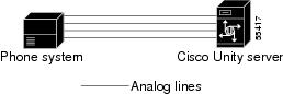
The Matra 6500 phone system communicates with the Cisco Unity server by using DTMF sequences. The voice messaging lines from the phone system connect to the analog voice cards in the Cisco Unity server. Figure 1 shows the required connections.

Figure 1 Connections Between the Phone System and Cisco Unity

The phone system sends the following information with forwarded calls:

The extension of the called party

The extension of the calling party (for internal calls) or the phone number of the calling party (if it is an external call and the system uses caller ID)

Cisco Unity uses this information to answer the call appropriately. For example, a call forwarded to Cisco Unity is answered with the personal greeting of the subscriber. If the phone system routes the call to Cisco Unity without this information, Cisco Unity answers with the opening greeting.

Integration Features

The Matra 6500 integration with Cisco Unity provides the following features:

Call forward to personal greeting

When an incoming call is routed to an unanswered or busy extension, the call is forwarded to the voice mail of the subscriber. The caller then hears the personal greeting of the subscriber and can leave a message.

Caller ID

Cisco Unity receives caller ID information from the phone system (if available). This information appears in the subject line of the message in the desktop messaging application.

Easy message access

A subscriber can retrieve messages without entering an ID. Cisco Unity identifies a subscriber based on the extension from which the call originated. A password may be required.

Identified subscriber messaging

Cisco Unity automatically identifies a subscriber who leaves a message during a forwarded internal call, based on the extension from which the call originated.

Message waiting indication

When a message is waiting for a subscriber, Cisco Unity notifies the phone system to activate the message waiting indicator (MWI) on the subscriber's extension (a lamp or a stutter dial tone).


Programming the Matra 6500 Phone System

If you use programming options other than those supplied in the following procedure, the performance of the integration may be affected.

If you want to remap extension numbers (for example, when multiple subscribers use a single phone, or when multiple extension numbers on a single phone should go to a single subscriber greeting), see "Remapping Extension Numbers" section.

The XMEVOC command requires the Q23 interface for integrating with Cisco Unity. The only supported voice mail type is Messagerie Vocale Q23. The V.24 interface is not supported. You can use this command to define:

The Q23 DTMF digits sent to Cisco Unity to trigger integration features.

The Q23 DTMF digits sent to the phone system to its features.

The XLIGAB command enables use of analog connections to Cisco Unity:

Defining voice messaging ports as Répondeur Q23.

Configuring all analog lines.


Caution In programming the phone system, do not forward calls to voice messaging ports in Cisco Unity that cannot answer calls (voice messaging ports that are not set to Answer Calls). For example, if a voice messaging port is set only to Dialout MWI, do not send calls to it.

To program the Matra 6500 phone system


Step 1 On the Matra 6500 phone system, use the XLIGAB command to view the Abonné Téléphonique page. Then configure each extension assigned to a voice messaging port with the following settings.

Table 1 Voice Messing Port Extension Settings 

Option
Setting

Type de Poste

Répondeur Q23

No d'Abonné du Groupement

<the pilot number (tête de groupement) for the hunt group (groupement)>


Step 2 Use the XGRABO command to view the Tête de Groupement page. Then assign the pilot number (tête de groupement) of the hunt group (groupement) with the following settings.

Table 2 Pilot Number Settings 

Option
Setting

No d'Abonné du Groupement

<the pilot number (tête de groupement) for the hunt group>

Tête de Groupement

Normal

Type de Groupement

Cyclique


Step 3 Assign the extensions for the voice messaging ports that answer calls to the hunt group (groupement) with the following settings.

Table 3 Hunt Group Settings 

Option
Setting

UCG

<the cluster (grappe) that the extensions for the voice messaging ports belong to; all voice messaging ports must be in the same société, service, and grappe>

Numéro abonné

<the extension for the voice messaging port that answers calls>

Etat

Actif


Step 4 Use the XGRABO command to view the Facilités Dynamiques page. Then assign the following settings for each extension in the hunt group.

Table 4 Call Forwarding Settings for Hunt Group Extensions 

Option
Setting

Reroutage Systèmatique

Non Activée

Reroutage sur Occupation (busy)

Activée

Num.

<the pilot number (tête de groupement) for the hunt group>

Type

Tous

Reroutage sur Non Réponse (no answer)

Activée

Num.

<the pilot number (tête de groupement) for the hunt group>

Type

Tous


Step 5 Program each phone to forward calls to the pilot number assigned to the voice messaging ports, based on one of the following Cisco Unity call transfer types shown in Table 5.

Table 5 Call Transfer Types 

Transfer Type
Usage

Release transfer
(blind transfer)

Program the phone to forward calls to the pilot number when:

The extension is busy

The call is not answered

Supervised transfer

Program the phone to forward calls to the pilot number only when the call is not answered. Confirm that call forwarding is disabled when the extension is busy.


Setting Up Cisco Unity Call Handlers

You must set up a call handler for each subscriber to enable the phone system to send callers to the mailbox for the subscriber they are calling.

Do the following procedure.

To set up call handlers for subscribers


Step 1 In the Cisco Unity Administrator, go to any Call Management > Call Handlers page.

Step 2 Click the Add icon.

Step 3 In the Add a Call Handler dialog box, enter the extension for a subscriber in the Name field.

For example, if the subscriber extension is 4150, enter 4150.

Step 4 Confirm that New Call Handler option is selected.

Step 5 Click Add.

Step 6 On the new call handler page, in the Extension field, enter 1<the subscriber extension>.

For example, if the subscriber extension is 4150, enter 14150.

Step 7 Go to the Call Handlers > Call Transfer page.

Step 8 Set the Transfer Rule Applies To field to Alternate.

Step 9 Confirm that the Enabled option is selected.

Step 10 In the Yes, Ring Subscriber field, enter *71<the subscriber extension>#.

For example, if the subscriber extension is 4150, enter *714150#.

Step 11 Go to the Call Handlers >

Step 12 Click the Save icon.

Step 13 In the Save Confirm dialog box, click Save. The Add a Call Handler dialog box appears. Close the dialog box.

Step 14 Go to the Call Handlers > Greetings page.

Step 15 Under After Greetings, click the Send Caller To option and confirm that Call Handler is selected in the drop-down box.

Step 16 Click Select Call Handler.

Step 17 In the Select Call Handler dialog box, click Find.

Step 18 In the Matching Call Handlers field, click the subscriber extension.

For example, if the subscriber extension is 4150, click 4150.

Step 19 Go to the Call Handlers > Messages page.

Step 20 Under After Message Action, click the Send Caller To option and click Hang Up in the drop-down box.

Step 21 Click the Save icon.

Step 22 In the Save Confirm dialog box, click Save. The Add a Call Handler dialog box appears.

Step 23 Repeat Steps 3 through 13 for each remaining subscriber.


Configuring Cisco Unity for the Integration

After ensuring that the Cisco Unity server is ready for the integration by completing the appropriate tasks in the Cisco Unity Installation Guide, perform the following procedures to confirm that the integration is enabled and to enter the port settings.

To confirm that the integration is enabled


Step 1 On the Cisco Unity server, go to the Cisco Unity Administrator by doing one of the following:

In Internet Explorer, go to http://<Cisco Unity server name>/web/sa.

Double-click the desktop shortcut to the Cisco Unity Administrator.

Step 2 Go to System > Licensing > Licensed Features.

Step 3 In the Integration field, confirm that the setting is Analog for a single phone system integration or Multiple Integrations for a dual phone system integration.

Step 4 If the setting is not Analog or Multiple Integrations, contact your sales representative for the necessary system key.

Step 5 Go to System > Switch. Confirm that the settings match those in Table 6. If the settings are incorrect, integration features may not be enabled.

Table 6 Switch Settings 

Switch Parameter
Required Setting

Manufacturer

Matra

Model

6500

Switch PBX Software Version

All

Integration

Analog


Step 6 If necessary, edit the codes that turn message waiting indication on and off. The MWI codes are located in the Active Switch Setting area at the top of the Switch Settings page.

Step 7 Click the Save icon.


To enter port settings


Step 1 In the Cisco Unity Administrator, go to System > Ports.

Step 2 Select a port in the table.

Step 3 Indicate the settings for the port.

If you are setting up a hunt group, use the first voice-messaging ports for incoming calls and the last ports to dial out. This helps minimize the possibility of a collision, in which an incoming call arrives on a port at the same time that Cisco Unity takes the port off-hook to dial out.

Step 4 Type the extension for the port.

Step 5 Repeat Steps 2 through 4 for the remaining ports.

Step 6 Click the Save icon.

Step 7 For the settings to take effect, exit and restart the Cisco Unity software.


Testing the Integration

To test whether Cisco Unity and the phone system are integrated correctly, perform the procedures in the order listed.

If any of the steps indicates a failure, see the following documentation as appropriate:

The installation guide for the phone system

Cisco Unity Troubleshooting Guide

The setup information earlier in this document

To set up the test configuration


Step 1 Set up two test extensions (Phone 1 and Phone 2) on the same phone system that Cisco Unity is connected to.

Step 2 Set Phone 1 to forward calls to the Cisco Unity pilot number when calls are not answered.

Step 3 In the Cisco Unity Administrator, go to Subscribers > Subscribers > Profile.

If Example Subscriber is not displayed, click the Find icon (the magnifying glass) in the title bar, then click Find, and select Example Subscriber in the list that appears.

Step 4 In the Extension field, enter the extension of Phone 1.

Step 5 Click the Save icon.

Step 6 In the navigation bar, click Call Transfer to go to Subscribers > Subscribers > Call Transfer for Example Subscriber.

For more information on transfer settings, refer to the "Subscriber Template Call Transfer Settings" section in the Help for the Cisco Unity Administrator.

Step 7 Under Transfer Incoming Calls, click Yes, Ring Subscriber's Extension, and confirm that the extension number is for Phone 1.

Step 8 Under Transfer Type, click Release to Switch.

Step 9 Click the Save icon.

Step 10 In the navigation bar, click Messages to go to Subscribers > Subscribers > Messages for Example Subscriber.

Step 11 Under Message Waiting Indicators (MWIs), check Use MWI for Message Notification.

Step 12 In the Extension field, enter x.

Step 13 Click the Save icon.

Step 14 Open the Status Monitor by doing one of the following:

In Internet Explorer, go to http://<server name>/web/sm.

Double-click the desktop shortcut to the Status Monitor.

On the Windows taskbar next to the clock, right-click the Cisco Unity icon and click Status Monitor.


To test an external call with release transfer


Step 1 From Phone 2, enter the access code necessary to get an outside line, then enter the number outside callers use to dial directly to Cisco Unity.

Step 2 On the Status Monitor, note the port that handles this call.

Step 3 When you hear the opening greeting, enter the extension for Phone 1. Hearing the opening greeting means that the port is configured correctly.

Step 4 Confirm that Phone 1 rings and that you hear a ringback tone on Phone 2. Hearing a ringback tone means that Cisco Unity released the call and transferred it to Phone 1.

Step 5 Leaving Phone 1 unanswered, confirm that the state of the port handling the call changes to "Idle." This state means that release transfer is successful.

Step 6 Confirm that, after the number of rings that the phone system is set to wait, the call is forwarded to Cisco Unity and that you hear the greeting for Example Subscriber. Hearing the greeting means that the phone system forwarded the unanswered call and the call-forward information to Cisco Unity, which correctly interpreted the information.

Step 7 On the Status Monitor, note the port that handles this call.

Step 8 Leave a message for Example Subscriber and hang up Phone 2.

Step 9 On the Status Monitor, confirm that the state of the port handling the call changes to "Idle." This state means that the port was successfully released when the call ended.

Step 10 Confirm that the MWI on Phone 1 is activated. The activated MWI means that the phone system and Cisco Unity are successfully integrated for turning on MWIs.


To test an internal call with release transfer


Step 1 From Phone 1, enter the internal pilot number for Cisco Unity.

Step 2 When asked for your password, enter 12345. Hearing the request for your password means that the phone system sent the necessary call information to Cisco Unity, which correctly interpreted the information.

Step 3 Confirm that you hear the recorded voice name for Example Subscriber. Hearing the voice name means that Cisco Unity correctly identified the subscriber by the extension.

Step 4 When asked whether you want to listen to your messages, press 1.

Step 5 After listening to the message, press 3 to delete the message.

Step 6 Confirm that the MWI on Phone 1 is deactivated. The deactivated MWI means that the phone system and Cisco Unity are successfully integrated for turning off MWIs.

Step 7 Hang up Phone 1.

Step 8 On the Status Monitor, confirm that the state of the port handling the call changes to "Idle." This state means that the port was successfully released when the call ended.


To set up supervised transfer on Cisco Unity


Step 1 In the Cisco Unity Administrator, go to Subscribers > Subscribers > Call Transfer.

If Example Subscriber is not displayed, click the Find icon (the magnifying glass) in the title bar, then click Find, and select Example Subscriber in the list that appears.

For more information on transfer settings, refer to the "Subscriber Template Call Transfer Settings" section in the Help for the Cisco Unity Administrator.

Step 2 Under Transfer Type, click Supervise Transfer.

Step 3 Set the Rings to Wait For field to 3.

Step 4 Click the Save icon.


To test supervised transfer


Step 1 From Phone 2, enter the access code necessary to get an outside line, then enter the number outside callers use to dial directly to Cisco Unity.

Step 2 On the Status Monitor, note the port that handles this call.

Step 3 When you hear the opening greeting, enter the extension for Phone 1. Hearing the opening greeting means that the port is configured correctly.

Step 4 Confirm that Phone 1 rings and that you do not hear a ringback tone on Phone 2. Instead, you should hear the indication your phone system uses to mean that the call is on hold (for example, music or beeps).

Step 5 Leaving Phone 1 unanswered, confirm that the state of the port handling the call remains "Busy." This state and hearing an indication that you are on hold mean that Cisco Unity is supervising the transfer.

Step 6 Confirm that, after three rings, you hear the greeting for Example Subscriber. Hearing the greeting means that Cisco Unity successfully recalled the supervised-transfer call.

Step 7 During the greeting, hang up Phone 2.

Step 8 On the Status Monitor, confirm that the state of the port handling the call changes to "Idle." This state means that the port was successfully released when the call ended.


To return Example Subscriber to the default settings


Step 1 In the Cisco Unity Administrator, go to Subscribers > Subscribers > Call Transfer.

If Example Subscriber is not displayed, click the Find icon (the magnifying glass) in the title bar, then click Find, and select Example Subscriber in the list that appears.

Step 2 Under Transfer Incoming Calls, click No (Send Directly to Subscriber's Greeting).

Step 3 In the navigation bar, click Profile to go to Subscribers > Subscribers > Profile.

Step 4 In the Extension field, enter 99990.

Step 5 Click the Save icon.

Step 6 In the navigation bar, click Messages to go to Subscribers > Subscribers > Messages for Example Subscriber.

Step 7 Under Message Waiting Indicators (MWIs), uncheck Use MWI for Message Notification.

Step 8 Click the Save icon.


Integrating a Secondary Server for Cisco Unity Failover

A Cisco Unity failover server is a secondary (or backup) server that provides voice messaging services if the primary Cisco Unity server becomes inactive. For information on installing a secondary server, refer to the Cisco Unity Installation Guide.

Requirements

The following components are required to integrate a Cisco Unity secondary server:

One secondary Cisco Unity server for each primary server installed and ready for the integration, as described in the Cisco Unity Installation Guide and earlier in this integration guide.

The appropriate cable configuration for each analog voice messaging port to simultaneously connect the phone system to the corresponding ports on both the primary and the secondary servers. For example, connect port 1 on the phone system with both port 1 on the primary server and port 1 on the secondary server.

A system key that enables the integration, the appropriate number of voice messaging ports, and the secondary server.

Integration Description

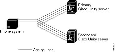
The phone system communicates with both the primary and secondary servers through the connecting cables. Figure 2 shows the required connections.

Figure 2 Connections Between the Phone System and Cisco Unity Servers

The primary and secondary servers act in the following manner:

When the primary server is operating normally, the secondary server is inactive.

When the primary server becomes inactive, the secondary server becomes active.

When the primary server becomes active again, the secondary server becomes inactive.

Setting Up a Secondary Server for Failover

Do the following procedure to integrate a Cisco Unity secondary server.

To set up the secondary server for failover


Step 1 Install a secondary server with the same configuration as the primary server. For installation instructions, refer to the Cisco Unity Installation Guide.

Step 2 Make all voice connections from the phone system to the corresponding ports on both the primary server and the secondary server. For example, connect port 1 from the phone system with port 1 on both the primary and the secondary servers.

Step 3 In the Cisco Unity Administrator of the secondary server, enter the settings on the System > Ports page to match the port settings on the primary server.


Caution In programming the phone system, do not forward calls to voice messaging ports in Cisco Unity that cannot answer calls (voice messaging ports that are not set to Answer Calls). For example, if a voice messaging port is set only to Dialout MWI, do not send calls to it.

Step 4 If the automatic failover that occurs when the secondary server receives a call is disabled, skip the remaining steps.

If the automatic failover that occurs when the secondary server receives a call is enabled (the default), on the Windows Start menu of the Cisco Unity server, click Programs > Unity >Edit Switch Utility.

Step 5 In the Switch Configuration Editor dialog box, click the Edit This Switch Configuration button.

Step 6 In the Switch Configuration dialog box, click the Incoming Calls tab.

Step 7 In the Call Rings field, enter 3 and click OK.

Step 8 Click Exit.

Step 9 For the settings to take effect, restart the Cisco Unity server.


No changes to the hunt group programming on the phone system are necessary.


Dual Phone System Integration


Cisco Unity can be integrated with one each of the following phone systems at the same time:

A traditional, circuit-switched phone system. Any circuit-switched phone system that Cisco Unity integrates with can be used in a dual phone system integration.

Cisco CallManager.

All extensions for subscribers and call handlers must be unique regardless of which phone system a subscriber (or call handler) uses. To transfer calls from one phone system to the other, Cisco Unity must dial the same access codes that a subscriber dials when calling someone on the other phone system.

Dual Phone System Integration Overview

Before performing the following integration steps, confirm that the Cisco Unity server is ready for the integration by completing the appropriate tasks in the Cisco Unity Installation Guide.

Integration Steps When No Phone Systems Are Installed

Follow these steps to set up the dual phone system integration when no phone systems are installed.

1. Install the circuit-switched phone system.

2. Integrate the circuit-switched phone system and Cisco Unity. See instructions earlier in this integration guide.

3. Install Cisco CallManager.

4. Integrate Cisco CallManager and Cisco Unity. See the appropriate Cisco CallManager integration guide, located on Cisco.com at http://www.cisco.com/univercd/cc/td/doc/product/voice/c_unity/index.htm and on the Cisco Documentation CD-ROM.

5. Change the Cisco Unity Administrator settings. See the "Changing Cisco Unity Administrator Settings" section.

Integration Steps When a Circuit-Switched Phone System Is Already Installed

Follow these steps to set up the dual phone system integration when the circuit-switched phone system is already installed and Cisco CallManager is being newly installed.

1. Install Cisco CallManager.

2. Integrate Cisco CallManager and Cisco Unity. See the appropriate Cisco CallManager integration guide, located on Cisco.com at http://www.cisco.com/univercd/cc/td/doc/product/voice/c_unity/index.htm and on the Cisco Documentation CD-ROM.

3. Change the Cisco Unity Administrator settings. See the "Changing Cisco Unity Administrator Settings" section.

Integration Steps When Cisco CallManager Is Already Installed

Follow these steps to set up the dual phone system integration when Cisco CallManager is already installed and a circuit-switched phone system is being newly installed.

1. Remove the existing TSP on Cisco Unity. See the "To remove the existing TSP" section.

2. Install the circuit-switched phone system.

3. Integrate the circuit-switched phone system and Cisco Unity. See the instructions earlier in this integration guide.

4. Reinstall the TSP. See the "To reinstall the TSP" section.

5. Change the Cisco Unity Administrator settings. See the "Changing Cisco Unity Administrator Settings" section.

Requirements

The dual phone system integration supports configurations of the following components:

A Cisco Unity system key with the integration type set to "Multiple integrations" and with the appropriate number of voice messaging ports enabled.

The Cisco Unity server set up and Cisco Unity 3.1(1) or later installed, as described in the Cisco Unity Installation Guide.

A circuit-switched phone system installed and integrated with Cisco Unity. For details, see the instructions earlier in this integration guide. The circuit-switched phone system (including the voice card software used in the integration) must be installed and integrated with Cisco Unity before Cisco CallManager is integrated.

Cisco CallManager, version 3.2(1) or later, and the Cisco Unity-CM service provider (TSP) installed and configured. For information about integrating Cisco Unity with Cisco CallManager and the Cisco Unity-CM service provider, see the appropriate Cisco CallManager integration guide, located on Cisco.com at http://www.cisco.com/univercd/cc/td/doc/product/voice/c_unity/index.htm and on the Cisco Documentation CD-ROM.

Changing Cisco Unity Administrator Settings

After Cisco Unity is installed and the phone systems have been separately integrated, you need to adjust settings on pages in the Cisco Unity Administrator so that Cisco Unity can work with both phone systems.

Follow these steps to set up the dual phone system integration.

1. Specify settings for the circuit-switched phone system on the System > Switch > Switch page. For details, see the "To specify switch settings for the circuit-switched phone system" section.


Caution Specify settings for the circuit-switched phone system before specifying settings for Cisco CallManager. You must proceed in this order, or the integration may not work.

2. Specify settings for Cisco CallManager on the IP Switch page. For details, see the "To specify switch settings for Cisco CallManager" section.

3. On the Ports page, assign port ranges to the circuit-switched phone system first, then to CallManager, and adjust settings for the ports assigned to each phone system. For details, see the "To modify voice port settings" section.

4. Select the phone system that subscribers and call handlers use. For details, see the "To select which phone system subscribers and call handlers use" section.

5. Select the phone system that Cisco Unity uses when dialing out to send message notifications. For details, see the "To select which phone system Cisco Unity uses for message notification" section.


Caution If you need to add or remove voice cards or uninstall the voice card software after the dual phone system integration is set up, you must also reinstall the TSP (Cisco Unity-CM service provider). Do not reinstall the TSP until after you have set up the voice cards or reinstalled the voice card software. For more information, see the "Changing the Number of Installed Ports" section.

To specify switch settings for the circuit-switched phone system


Step 1 Go to System > Switch > Switch. The settings for the circuit-switched phone system selected during the Cisco Unity Setup program appear.

Step 2 In the Access Code field, enter the trunk access code that Cisco Unity must dial to transfer calls to Cisco CallManager from the circuit-switched phone system.

The access code is the same number that subscribers on the circuit-switched phone system dial to reach someone on the Cisco CallManager system.

Step 3 Adjust other settings as appropriate. For more information about the other settings on the Switch page, see the online Help in the Cisco Unity Administrator.

Step 4 Click the Save icon, then click OK in the Warning dialog box.


To specify switch settings for Cisco CallManager


Step 1 Go to System > Switch > IP Switch.

Step 2 In the Set Active Switch Type section, enter values as shown in the following table:

Table 7 Switch Settings 

Switch Parameter
Required Setting

Manufacturer

Cisco

Model

CallManager

Switch PBX software version

3.01 or later

Integration

TAPI


Step 3 Click Set As Active, then click OK in the Warning dialog box.

Step 4 In the Access Code field, enter the trunk access code that Cisco Unity must dial to transfer calls to the circuit-switched phone system from Cisco CallManager.

The access code is the same number that subscribers on Cisco CallManager dial to reach someone on the circuit-switched phone system.

Step 5 Click the Save icon, then click OK in the Warning dialog box.


To modify voice port settings


Step 1 Go to System > Ports.

Step 2 In the Port Assignments section, indicate the range of ports to be assigned to the circuit-switched phone system. The port range for the circuit-switched phone system begins with 1 and extends to no more than the number of ports that are on the installed voice cards. Do not assign more ports to the circuit-switched phone system than the number of ports on the voice cards.


Caution If you assign fewer voice ports to the circuit-switched phone system than are available on the installed voice cards, you must edit the registry for this port range to take effect. Otherwise, all available voice ports on the voice cards are used in the integration regardless of the Port Assignments settings. For information on editing the registry for the port range, see the appendix "Assigning Dialogic Ports for a Dual Phone System Integration."

Step 3 In the Port Assignments section, indicate the range of ports to be assigned to Cisco CallManager. The port range must begin with the next port after the last port for the circuit-switched phone system. The range for Cisco CallManager must end with the port number of the last port displayed on the Ports page, or the number of licensed voice ports on the system key, whichever is lower. In other words, the number of ports available for Cisco CallManager is the difference between the number of licensed voice ports on the system key and the number of ports assigned to the circuit-switched phone system.

Step 4 Enter an extension for each port.

Step 5 Specify other settings as appropriate. For each phone system, confirm that an appropriate number of ports are used to answer calls and to dial out for message waiting indicators (MWIs), message notifications, and Media Master recordings by phone.

Step 6 Click the Save icon.


Caution The port range for each phone system must be set as specified in Steps 2 and 3 above. If there is a port range mismatch, Cisco Unity will be unable to answer incoming calls and to dial out.


To select which phone system subscribers and call handlers use

For existing subscriber templates, subscriber accounts, and call handlers, Cisco Unity uses the circuit-switched phone system as its default. Therefore, during the initial setup of the dual phone integration, you will modify only those pages that will be using Cisco CallManager. Note that changes made to subscriber templates do not affect existing subscriber accounts.


Step 1 In Cisco Unity Administrator, go to the appropriate page:

Subscribers > Subscriber Template > Profile

Subscribers > Subscribers > Profile

Call Management > Call Handlers > Profile

Step 2 In the Switch list, select the appropriate phone system.

Step 3 Adjust other settings as appropriate. For more information, see the online Help in the Cisco Unity Administrator.


Caution If the Switch setting on the Profile page for the subscriber or call handler does not match the phone system actually used by a subscriber or call handler, Cisco Unity will not be able to transfer calls to or from the subscriber or call handler. Additionally, Cisco Unity will be unable to turn the MWIs for the subscriber on or off and will be unable to reach the extension for the subscriber when recording by phone with Media Master.


To select which phone system Cisco Unity uses for message notification

If subscribers use message notification, you can select which phone system Cisco Unity dials out on when notifying subscribers of new messages. Note that changes made to subscriber templates do not affect existing subscribers.


Step 1 In Cisco Unity Administrator, go to the appropriate page:

Subscribers > Subscriber Template > Message Notification

Subscribers > Message Notification.

Step 2 For each device, in the Switch list select the phone system that Cisco Unity uses to dial out when notifying subscribers of new messages. Each notification device can be associated with a specific phone system (except for text pagers).

Cisco Unity uses the phone system specified on the subscriber template's Profile page as the default.

Step 3 Adjust other settings as appropriate. For more information, see the online Help in the Cisco Unity Administrator.


Caution The selected phone system must have at least one port set to dial out for message notifications on the System > Ports page. If the selected phone system does not have any ports set for this function, notifications will fail.


Changing the Number of Installed Ports

After the dual phone system integration is set up, if you need to add or remove voice cards or uninstall voice card software, follow these steps:

1. Remove the existing TSP. For details, see the "To remove the existing TSP" section. (In versions earlier than 3.1(1), the Cisco Unity-CM TSP was known as the AV-Cisco TSP.)

2. As appropriate, remove or add voice cards, or uninstall and reinstall the voice card software. For information about removing Dialogic voice card software, refer to the chapter about voice cards in the Cisco Unity Installation Guide.

3. Reinstall the TSP after you have set up the voice cards or reinstalled the voice card software. For details, see "To reinstall the TSP" section.

4. Adjust the port assignments on the System > Ports page. The voice messaging ports must appear in this order in the list of ports: first are all the ports connected to the circuit-switched phone system, second are the ports connected to CallManager.

If you completely remove the circuit-switched phone system, you must adjust the port assignments for Cisco CallManager on the System > Ports page, after the voice cards and voice card software used in the integration with the circuit-switched phone system have been removed.

To remove the existing TSP


Step 1 On the Cisco Unity server, log on to Windows as an administrator.

Step 2 Stop Cisco Unity (right-click the Cisco Unity icon in the system tray, then click Stop Unity).

Step 3 On the Windows Start menu, click Settings > Control Panel > Add/Remove Programs.

Step 4 In the list, click Cisco Unity-CM TSP.


Note In versions earlier than 3.1(1), the Cisco Unity-CM TSP was known as the AV-Cisco TSP.


Step 5 Click Remove.

Step 6 Click Yes.

Step 7 Close Control Panel.


To reinstall the TSP


Step 1 On the Cisco Unity server, log on to Windows as an administrator.

Step 2 On the Windows Start menu, click Settings > Control Panel.

Step 3 Double-click Phone and Modem Options. The Phone and Modem Options dialog box appears.

Step 4 Click the Advanced tab.

Step 5 Click Add. The Add Driver dialog box appears.

Step 6 Click Cisco Unity-CM Service Provider, then click Add. A dialog box appears confirming the installation of the TSP.

Step 7 Click OK to close the dialog box.

Step 8 Click Close to close the Phone and Modem Options dialog box.

Step 9 Close Control Panel.

Step 10 Restart the Cisco Unity server.


Remapping Extension Numbers


The Remapping Feature

The extension remapping feature lets you convert the calling numbers and forwarding numbers of calls that Cisco Unity handles to the extensions of your choice. This feature is useful, for example, when the phone system cannot map multiple extension numbers on a subscriber's phone to a single Inbox.

Remapping can change one or both of the following extension numbers in a call:

Calling number (the number from which a call originates). For example, Cisco Unity changes the calling number of calls that the phone system sends it so that the caller ID appears to be a different extension than the one that actually placed the call.

Forwarding number (the number that a call is going to). For example, unanswered calls to all line extensions on a single phone can be forwarded to the Inbox of a single subscriber; or unanswered calls to phones not assigned to subscribers can be forwarded to the Inbox of a supervisor.

Setting Up Cisco Unity to Remap Extension Numbers

This section includes a procedure for enabling the remapping feature. There are also examples of extension remapping syntax.

By performing the procedure, you can create multiple files in either or both of two directories:

In the Calling directory, one or more .exm files remap caller ID numbers.

In the Forwarding directory, one or more .exm files remap numbers that Cisco Unity provides with calls it forwards.

Creating remapping instructions in an .exm file in a directory remaps only the type of extension number that the directory is named for. For example, if you want to remap only the extensions that Cisco Unity provides with calls it forwards, you must enter the instructions in an .exm file in the Forwarding directory; the Calling directory needs no file in this case.

In each directory, you can have several .exm files with different file names but the same .exm extension to help organize the remapping information (for example, Ports_1-12.exm and Ports_13-24.exm). Cisco Unity reads all files that have the .exm extension in these directories.

To remap extension numbers


Step 1 On the Cisco Unity server, browse to the CommServer\IntLib\ExtensionMapping directory. In this directory is the file Sample.txt and two more directories: Calling and Forwarding.

Step 2 To remap calling numbers, go to the Calling directory.

Step 3 Using a text editor, create (or open) an .exm file in one directory.

For a sample file, see the file Sample.txt in the CommServer\IntLib\ExtensionMapping directory. To create a section for indicating which voice messaging ports will be monitored for remapping calls, enter [Range] and press Return.

An .exm file can have only one [Range] section.

Step 4 Enter ports= followed by the numbers of the voice messaging ports separated by commas. Ranges are designated by a hyphen (-) without spaces. To monitor all voice messaging ports, enter ports=* on this line. Then press Return.

For example, you might enter:

ports=1,2,5-34,10

Step 5 To create a section for the remapping rules, press Return, enter [Number Mappings], and then press Return.

An .exm file can have only one [Number Mappings] section.

Step 6 Using the wildcards and examples in the following "Syntax and Examples" section, enter one remapping rule on the line. Then press Return. The rule format is:

<original number>, <new number>

The rules cannot include spaces between digits. However, the numbers must be separated by a comma and a single space. Wildcard characters cannot appear at the beginning of a number.

Step 7 For all remaining rules, repeat Step 6.

Step 8 Save and close the .exm file.

Step 9 To remap forwarding numbers, go to the directory CommServer\IntLib\ExtensionMapping\Forwarding.

Step 10 Perform Steps 3 through 8.

Step 11 For extension remapping to take effect, restart the Cisco Unity software.


Syntax and Examples

Table 8 lists the wildcard characters you can use in the .exm files.

Table 8 Wildcard Characters 

Wildcard
Result

*

Matches zero or more digits.

?

Matches exactly one digit. Use ? as a placeholder for a single digit.


Table 9 gives examples for the syntax and results of rules in the .exm files.

Table 9 Syntax Examples 

Rule
Original Number
New Number

2189, 1189

3189, 1189

4189, 1189

2189

3189

4189

1189

1189

1189

2???, 1???

2189

2291

1189

1291

3???, 1???

3189

3291

1189

1291

8???, 61???

8000

8765

61000

61765

123*, 44*

12300

12385

4400

4485


Cisco Unity executes rules in the order they appear in the .exm file. For example, the .exm file might contain the following rules:

1234, 1189
3189, 1189
4189, 1189
123?, 8891

The extension 1234 would be remapped to 1189 while extensions 1233 and 1235 would be remapped to 8891, because the rule mapping 1234 appears earlier.

An .exm file might contain the following:

[Range]
ports=1,2,5-34,10

[Number Mappings]
2189, 1189
3189, 1189
4189, 1189
8???, 9???


Assigning Dialogic Ports for a Dual Phone System Integration


In a dual phone system integration, Cisco Unity assigns a voice messaging port to the traditional, circuit-switched phone system for every port available on the installed voice cards before assigning voice messaging ports to Cisco CallManager. The result is that Cisco Unity may not have enough voice messaging ports remaining to assign to Cisco CallManager.

The maximum number of voice messaging ports are assigned to the circuit-switched phone system in spite of the settings on the Ports page in the System Administrator.

For example, a dual phone system integration might have the following configuration:

A circuit-switched phone system has a four-port voice card installed.

Cisco CallManager has six Voice Mail ports set up.

The Cisco Unity server has a system key enabled for a total of eight ports.

The Ports page on System Administrator indicates that Ports 1 and 2 are assigned to the circuit-switched phone system and Ports 3 through 8 are assigned to Cisco CallManager.

Even so, Ports 1 through 4 (the total voice card ports) will be assigned to the circuit-switched phone system, and Ports 5 through 6 will be assigned to Cisco CallManager.

If you want to assign fewer than the total voice card ports to the circuit-switched phone system, you must first set the Port assignments on the Ports page of the System Administrator, then perform the following procedure.

To set the Port assignments in the Registry


Step 1 On the Cisco Unity server, click Start > Run.

Step 2 In the Open field, enter Regedit and press Enter. The Registry Editor appears.


Caution Changing the wrong registry key or entering an incorrect value can cause the server to malfunction. Before you edit the registry, confirm that you know how to restore it if a problem occurs. (Refer to the "Restoring" topics in Registry Editor Help.) Note that a typical backup of the Cisco Unity server does not back up the registry. Also note that for a Cisco Unity failover system, registry changes on one Cisco Unity server must be made manually on the other Cisco Unity server, because registry changes are not replicated. If you have any questions about changing registry key settings, contact Cisco TAC.

Step 3 If you do not have a current backup of the registry, click Registry > Export Registry File, and save the registry settings to a file.

Step 4 Go to HKEY_LOCAL_MACHINE\Software\ActiveVoice\MIU\1.0\Initialization\ServiceProvider <x>, where <x> is a number.

You will find several subkeys with this name.

Step 5 Locate the subkey in which the value Service Provider Name is D41MT.TSP.

Step 6 In this subkey, in the Edit menu click New > DWORD Value. A new value appears in the subkey.

Step 7 Enter the name DeviceID Lower Bound and press Enter.

Step 8 Double-click the DeviceID Lower Bound value. The Edit DWORD Value dialog box appears.

Step 9 In the Value Data field, enter 1 and click OK.

Step 10 in the Edit menu click New > DWORD Value. A new value appears in the subkey.

Step 11 Enter the name DeviceID Upper Bound and press Enter.

Step 12 Double-click the DeviceID Upper Bound value. The Edit DWORD Value dialog box appears.

Step 13 In the Value Data field, enter the number of Dialogic ports you want to assign and click OK.

Step 14 Close the Registry Editor.

Step 15 For the settings to take effect, exit and restart the Cisco Unity software.


Documentation and Technical Assistance


Conventions

The Matra 6500 DTMF Integration Guide for Cisco Unity 3.1 uses the following conventions.

Table 10 Matra 6500 DTMF Integration Guide for Cisco Unity 3.1 conventions 

Convention
Description

boldfaced text

Boldfaced text is used for:

Key and button names. (Example: Click OK.)

Information that you enter. (Example: Enter Administrator in the User Name box.)

< >

(angle brackets)

Angle brackets are used around parameters for which you supply a value. (Example: In the Command Prompt window, enter ping <IP address>.)

-

(hyphen)

Hyphens separate keys that must be pressed simultaneously. (Example: Press Ctrl-Alt-Delete.)

>

(right angle
bracket)

A right angle bracket is used to separate selections that you make:

On menus. (Example: On the Windows Start menu, click Settings > Control Panel > Phone and Modem Options.)

In the navigation bar of the Cisco Unity Administrator. (Example: Go to System > Configuration > Settings.)

software version
numbers

In general, version numbers are not included in references to third-party software products, unless the information concerns a specific software version. For currently supported versions of third-party software products, refer to the "Supported Optional Microsoft Service Packs," "Supported Optional Third-Party Software," and "Supported Third-Party Fax Server Software" sections in Cisco Unity System Requirements, and Supported Hardware and Software on Cisco.com at http://www.cisco.com/univercd/cc/td/doc/product/voice/c_unity/sysreq/index.htm.


The Matra 6500 DTMF Integration Guide for Cisco Unity 3.1 also uses the following convention:


Note Means reader take note. Notes contain helpful suggestions or references to material not covered in the document.


Caution Means reader be careful. In this situation, you might do something that could result in equipment damage or loss of data.

Cisco Unity Documentation

Table 11 Cisco Unity Documentation Set 

Document
Location

Cisco Unity System Requirements, and Supported Hardware and Software

Available on Cisco.com at http://www.cisco.com/univercd/cc/td/doc/product/voice/c_unity/sysreq/index.htm and on the Cisco Documentation CD-ROM.

Cisco Unity System Administration Setup Worksheets

Available on Cisco.com at http://www.cisco.com/univercd/cc/td/doc/product/voice/c_unity/index.htm.

Cisco Unity Release Notes

Available on Cisco.com at http://www.cisco.com/univercd/cc/td/doc/product/voice/c_unity/index.htm and on the Cisco Documentation CD-ROM.

Also available on the Cisco Software Center website at http://www.cisco.com/kobayashi/sw-center/sw-voice.shtml.

Cisco Unity-CM TSP Release Notes

Available on Cisco.com at http://www.cisco.com/univercd/cc/td/doc/product/voice/c_unity/tsp/index.htm and on the Cisco Documentation CD-ROM.

Also available on the Cisco Software Center website at http://www.cisco.com/kobayashi/sw-center/sw-voice.shtml.

Cisco Unity Installation Guide

Available in print, on Cisco.com at http://www.cisco.com/univercd/cc/td/doc/product/voice/c_unity/index.htm, and on the Cisco Documentation CD-ROM.

Cisco Unity Bridge Installation Guide

Available in print, on Cisco.com at http://www.cisco.com/univercd/cc/td/doc/product/voice/c_unity/index.htm, and on the Cisco Documentation CD-ROM.

Cisco Unity integration guides for various phone systems

Available on Cisco.com at http://www.cisco.com/univercd/cc/td/doc/product/voice/c_unity/index.htm and on the Cisco Documentation CD-ROM.

Cisco Unity System Administration Guide

Available on Cisco.com at http://www.cisco.com/univercd/cc/td/doc/product/voice/c_unity/index.htm and on the Cisco Documentation CD-ROM.

Cisco Unity Failover Guide

Available on Cisco.com at http://www.cisco.com/univercd/cc/td/doc/product/voice/c_unity/index.htm and on the Cisco Documentation CD-ROM.

Networking in Cisco Unity

Available on Cisco.com at http://www.cisco.com/univercd/cc/td/doc/product/voice/c_unity/index.htm and on the Cisco Documentation CD-ROM.

Cisco Unity Troubleshooting Guide

Available on Cisco.com at http://www.cisco.com/univercd/cc/td/doc/product/voice/c_unity/index.htm and on the Cisco Documentation CD-ROM.

Cisco Unity User Guide

Available on Cisco.com at http://www.cisco.com/univercd/cc/td/doc/product/voice/c_unity/index.htm.

Cisco Unity at a Glance for Standard Conversation card

Available on Cisco.com at http://www.cisco.com/univercd/cc/td/doc/product/voice/c_unity/index.htm.

Cisco Unity at a Glance for Optional Conversation 1 card

Available on Cisco.com at http://www.cisco.com/univercd/cc/td/doc/product/voice/c_unity/index.htm.

Online Help

Available in:

The Cisco Unity ActiveAssistant (context-sensitive)

The Cisco Unity Administrator (context-sensitive)

The Cisco Unity Visual Messaging Interface (context-sensitive)

ViewMail for Microsoft Outlook

Regulatory Compliance and Safety Information for Cisco Unity

Available in print, on Cisco.com at http://www.cisco.com/univercd/cc/td/doc/product/voice/c_unity/index.htm, and on the Cisco Documentation CD-ROM.

Cisco Unity white papers and application notes

Available on Cisco.com at http://www.cisco.com/univercd/cc/td/doc/product/voice/c_unity/whitpapr/index.htm and on the Cisco Documentation CD-ROM.

Translated Cisco Unity documentation

Pieces of the Cisco Unity documentation set are available in French and German on Cisco.com at http://www.cisco.com/univercd/cc/td/doc/product/voice/c_unity/trans/index.htm.


Obtaining Documentation

The following sections explain how to obtain documentation from Cisco Systems.

World Wide Web

You can access the most current Cisco documentation on the World Wide Web at the following URL:

http://www.cisco.com

Translated documentation is available at the following URL:

http://www.cisco.com/public/countries_languages.shtml

Documentation CD-ROM

Cisco documentation and additional literature are available in a Cisco Documentation CD-ROM package, which is shipped with your product. The Documentation CD-ROM is updated monthly and may be more current than printed documentation. The CD-ROM package is available as a single unit or through an annual subscription.

Ordering Documentation

Cisco documentation is available in the following ways:

Registered Cisco.com users (Cisco direct customers) can order Cisco product documentation from the Networking Products MarketPlace:

http://www.cisco.com/cgi-bin/order/order_root.pl

Registered Cisco.com users can order the Documentation CD-ROM through the online Subscription Store:

http://www.cisco.com/go/subscription

Nonregistered Cisco.com users can order documentation through a local account representative by calling Cisco corporate headquarters (California, USA) at 408 526-7208 or, elsewhere in North America, by calling 800 553-NETS (6387).

Documentation Feedback

If you are reading Cisco product documentation on Cisco.com, you can submit technical comments electronically. Click the Fax or Email option under the "Leave Feedback" at the bottom of the Cisco Documentation home page.

You can e-mail your comments to bug-doc@cisco.com.

To submit your comments by mail, use the response card behind the front cover of your document, or write to the following address:

Cisco Systems
Attn: Document Resource Connection
170 West Tasman Drive
San Jose, CA 95134-9883

We appreciate your comments.

Obtaining Technical Assistance

Cisco provides Cisco.com as a starting point for all technical assistance. Customers and partners can obtain documentation, troubleshooting tips, and sample configurations from online tools by using the Cisco Technical Assistance Center (TAC) Web Site. Cisco.com registered users have complete access to the technical support resources on the Cisco TAC Web Site.

Cisco.com

Cisco.com is the foundation of a suite of interactive, networked services that provides immediate, open access to Cisco information, networking solutions, services, programs, and resources at any time, from anywhere in the world.

Cisco.com is a highly integrated Internet application and a powerful, easy-to-use tool that provides a broad range of features and services to help you to

Streamline business processes and improve productivity

Resolve technical issues with online support

Download and test software packages

Order Cisco learning materials and merchandise

Register for online skill assessment, training, and certification programs

You can self-register on Cisco.com to obtain customized information and service. To access Cisco.com, go to the following URL:

http://www.cisco.com

Technical Assistance Center

The Cisco TAC is available to all customers who need technical assistance with a Cisco product, technology, or solution. Two types of support are available through the Cisco TAC: the Cisco TAC Web Site and the Cisco TAC Escalation Center.

Inquiries to Cisco TAC are categorized according to the urgency of the issue:

Priority level 4 (P4)—You need information or assistance concerning Cisco product capabilities, product installation, or basic product configuration.

Priority level 3 (P3)—Your network performance is degraded. Network functionality is noticeably impaired, but most business operations continue.

Priority level 2 (P2)—Your production network is severely degraded, affecting significant aspects of business operations. No workaround is available.

Priority level 1 (P1)—Your production network is down, and a critical impact to business operations will occur if service is not restored quickly. No workaround is available.

Which Cisco TAC resource you choose is based on the priority of the problem and the conditions of service contracts, when applicable.

Cisco TAC Web Site

The Cisco TAC Web Site allows you to resolve P3 and P4 issues yourself, saving both cost and time. The site provides around-the-clock access to online tools, knowledge bases, and software. To access the Cisco TAC Web Site, go to the following URL:

http://www.cisco.com/tac

All customers, partners, and resellers who have a valid Cisco services contract have complete access to the technical support resources on the Cisco TAC Web Site. The Cisco TAC Web Site requires a Cisco.com login ID and password. If you have a valid service contract but do not have a login ID or password, go to the following URL to register:

http://www.cisco.com/register/

If you cannot resolve your technical issues by using the Cisco TAC Web Site, and you are a Cisco.com registered, you can open a case online by using the TAC Case Open tool at the following URL:

http://www.cisco.com/tac/caseopen

If you have Internet access, it is recommended that you open P3 and P4 cases through the Cisco TAC Web Site.

Cisco TAC Escalation Center

The Cisco TAC Escalation Center addresses issues that are classified as priority level 1 or priority level 2; these classifications are assigned when severe network degradation significantly impacts business operations. When you contact the TAC Escalation Center with a P1 or P2 problem, a Cisco TAC engineer will automatically open a case.

To obtain a directory of toll-free Cisco TAC telephone numbers for your country, go to the following URL:

http://www.cisco.com/warp/public/687/Directory/DirTAC.shtml

Before calling, please check with your network operations center to determine the level of Cisco support services to which your company is entitled; for example, SMARTnet, SMARTnet Onsite, or Network Supported Accounts (NSA). In addition, please have available your service agreement number and your product serial number.


[an error occurred while processing this directive]