[an error occurred while processing this directive]

Cisco Unity

Avaya Definity Gx/PBXLink Integration Guide for Cisco Unity 3.1

 Feedback

Table Of Contents

Avaya Definity Gx/PBXLink Integration Guide for Cisco Unity 3.1

Integration Tasks

Integration Steps

Requirements

Integration Description

Integration Features

Planning How the Voice Messaging Ports Will Be Used by Cisco Unity

Preparing for Programming the Phone System

Programming the Avaya Definity/PBXLink Phone System

Setting up the PBXLink Box

Configuring Cisco Unity for the Integration

Testing the Integration

Integrating a Secondary Server for Cisco Unity Failover

Requirements

Integration Description

Setting Up the Secondary Server for Failover


Dual Phone System Integration

Dual Phone System Integration Overview

Integration Steps When No Phone Systems Are Installed

Integration Steps When a Circuit-Switched Phone System Is Already Installed

Integration Steps When Cisco CallManager Is Already Installed

Requirements

Changing Cisco Unity Administrator Settings

Changing the Number of Installed Ports


Appendix: Remapping Extension Numbers

About the Remapping Feature

Setting Up Cisco Unity to Remap Extension Numbers

Syntax and Examples


Appendix: Assigning Dialogic Ports for a Dual Phone System Integration


Appendix: Documentation and Technical Assistance

Conventions

Obtaining Documentation

Cisco.com

Documentation DVD

Ordering Documentation

Documentation Feedback

Cisco Product Security Overview

Reporting Security Problems in Cisco Products

Obtaining Technical Assistance

Cisco Technical Support Website

Submitting a Service Request

Definitions of Service Request Severity

Obtaining Additional Publications and Information


Avaya Definity Gx/PBXLink Integration Guide for Cisco Unity 3.1


Revised February 10, 2005

This document provides instructions for integrating the phone system with the Cisco Unity voice messaging system.

Integration Tasks

Before performing the following tasks to integrate Cisco Unity with the Avaya Definity/PBXLink phone system, confirm that the Cisco Unity server is ready for the integration by completing the appropriate tasks in the Cisco Unity Installation Guide.

Integration Steps

Follow these steps to set up this integration.

1. Review the system and equipment requirements to confirm that all phone system and Cisco Unity server requirements have been met. See the "Requirements" section.

2. Plan how the voice messaging ports will be used by Cisco Unity. See the "Planning How the Voice Messaging Ports Will Be Used by Cisco Unity" section.

3. Program the Avaya Definity/PBXLink phone system and extensions. See the "Programming the Avaya Definity/PBXLink Phone System" section.

4. Install and configure the PBXLink box. See the "Setting up the PBXLink Box" section.

5. Configure Cisco Unity for the integration. See the "Configuring Cisco Unity for the Integration" section.

6. Test the integration. See the "Testing the Integration" section.

7. If you have Cisco Unity failover, integrate the secondary server. (Cisco Unity failover is supported only for release 3.1(2) and later.) See the "Integrating a Secondary Server for Cisco Unity Failover" section.

Requirements

The Avaya Definity/PBXLink integration supports configurations of the following components:

Phone System

An Avaya Definity phone system with one or two digital lines connected to the PBX ports on the PBXLink box. The line or lines must be compatible with the 7434D or 8434D digital phones. If vectoring will be used and depending on the phone system, the line or lines may require compatibility with only the 7434D digital phone.

Bridged mode feature, enabled.

For each voice messaging port, one analog port connected to the voice cards in the Cisco Unity server.

The SMDI port in the PBXLink box connected to a serial port (COM1 is the default) on the Cisco Unity server with an RS-232 serial cable. If multiple PBXLink boxes are installed, the SMDI port of the last PBXLink box is connected to the Management port of the first PBXLink box with an RS-232 serial cable. The SMDI port of the first PBXLink box is connected to a serial port (COM1 is the default) on the Cisco Unity server with another RS-232 serial cable. Make sure that the serial protocol parameters for the Management port of the first PBXLink box are set to the same values as the SMDI port. We recommend that the serial cables have the following construction for the serial cable:

A maximum of 50 feet (15.24 m) in length

24 AWG stranded conductors

Low capacitance—for example, no more than 12 pF/ft (39.4 pF/m) between conductors

At least 65 percent braided shield over aluminized polymer sleeve around conductors

UL-recognized overall cable jacket insulation with low dielectric constant

Braided shield fully terminated to and enclosed by a metal connector backshell

Gold-plated connector contacts

The phone system ready for the integration as described in the installation guide for the phone system.

Cisco Unity Server

The applicable voice cards, installed. For details on supported voice cards, refer to Cisco Unity System Requirements, and Supported Hardware and Software, available on Cisco.com at http://www.cisco.com/en/US/products/sw/voicesw/ps2237/prod_pre_installation_guides_list.html.

Cisco Unity installed and ready for the integration, as described in the Cisco Unity Installation Guide.

A system key that enables the integration and the appropriate number of voice messaging ports.

An available serial port (COM1 is the default).

Integration Description

The Avaya Definity/PBXLink integration uses one or more PBXLink boxes, with each box emulating up to two Avaya 7434D or 8434D digital phones. The PBXLink is connected to the phone system with digital phone lines and connected to the Cisco Unity server with an RS-232 serial cable. The voice messaging lines from the phone system connect to the analog voice cards in the Cisco Unity server.

This integration requires that bridged mode be used.

The PBXLink box receives the following call information from the phone system:

The extension of the called party

The reason for the forward (the extension is busy, does not answer, or is set to forward all calls)

The extension of the calling party (for internal calls) or the phone number of the calling party (if it is an external call and the system uses caller ID)

The PBXLink box formats this information as a Simplified Message Desk Interface (SMDI) packet and sends the packet to Cisco Unity through the RS-232 serial cable.

Cisco Unity uses this information to answer the call appropriately. For example, a call forwarded to Cisco Unity is answered with the personal greeting of the subscriber. If the phone system routes the call to Cisco Unity without this information, Cisco Unity answers with the opening greeting.

Cisco Unity also activates or deactivates messaging waiting indicators (MWIs) through the analog voice messaging ports rather than through the serial data link as in other serial integrations. As a result, it is necessary to set some voice messaging ports for handling MWIs as described in the "Planning How the Voice Messaging Ports Will Be Used by Cisco Unity" section, and to enter the MWI on and off codes as described in the "Configuring Cisco Unity for the Integration" section.

For more information on the PBXLink box, refer to the PBXLink documentation, which is available from the manufacturer.

Configuration for 24 or Fewer Ports

Avaya Definity/PBXLink integrations with 24 or fewer ports can use the following configuration (others are possible):

(Recommended) A single PBXLink-24 box with Port A set for calls only.

Configuration for 25 to 48 Ports

Avaya Definity/PBXLink integrations with 25 to 48 ports can use the following configuration (others are possible):

(Recommended) A single PBXLink-48 box with Ports A and B set for calls only.

Two PBXLink-24 boxes with Port A of both set for calls only.

Configuration for 49 to 72 Ports

Avaya Definity/PBXLink integrations with 49 to 72 ports can use one of the following configurations (others are possible):

(Recommended) One PBXLink-24 box with Port A set for calls only, and a PBXLink-48 box with Ports A and B of both set for calls only.

Two PBXLink-48 boxes with Ports A and B of both set for calls only.

Three PBXLink-24 boxes with Port A of all three set for calls only.

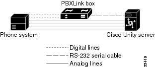
PBXLink Box Connections

A single PBXLink box is connected to the phone system with one or two digital phone lines and connected to the Cisco Unity server with an RS-232 serial cable. The voice messaging lines from the phone system connect to the analog voice cards in the Cisco Unity server. Figure 1 shows the required connections.

Figure 1 Serial Connection Between a Single PBXLink Box and Cisco Unity

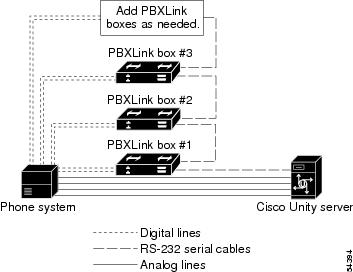
Multiple PBXLink boxes are connected to the Cisco Unity server by using an RS-232 cable to connect the SMDI port from the last PBXLink box to the Management port of the first PBXLink box. Another RS-232 cable is then used to connect the SMDI port of the first PBXLink box to the Cisco Unity server. The voice messaging lines from the phone system connect to the analog voice cards in the Cisco Unity server. Figure 2 shows the required connections.

Figure 2 Serial Connections Between Multiple PBXLink Boxes and Cisco Unity

Integration Features

The Avaya Definity/PBXLink integration with Cisco Unity provides the following features.

Call forward to personal greeting

When an incoming call is routed to an unanswered extension, the call is forwarded to the voice mail of the subscriber. The caller then hears the personal greeting of the subscriber and can leave a message.

Call forward to busy greeting

When an incoming call is routed to a busy extension, the call is forwarded to the voice mail of the subscriber. The caller then hears the busy greeting (if the subscriber enabled it) and can leave a message.

Caller ID

Cisco Unity receives caller ID information from the phone system (if available). This information appears in the subject line of the message in the desktop messaging application.

Easy message access

A subscriber can retrieve messages without entering an ID. Cisco Unity identifies a subscriber based on the extension from which the call originated. A password may be required.

Identified subscriber messaging

Cisco Unity automatically identifies a subscriber who leaves a message during a forwarded internal call, based on the extension from which the call originated.

Message waiting indication

When a message is waiting for a subscriber, Cisco Unity notifies the phone system to activate the message waiting indicator (MWI) on the subscriber extension.


Planning How the Voice Messaging Ports Will Be Used by Cisco Unity

Before programming the phone system, you need to plan how the voice messaging ports will be used by Cisco Unity. The following considerations will affect the programming for the phone system (for example, setting up the hunt group or call forwarding for the voice messaging ports):

The number of voice messaging ports installed.

The number of voice messaging ports that will answer calls.

The number of voice messaging ports that will only dial out, for example, to send message notification, to set message waiting indicators (MWIs), to make AMIS deliveries, and to make telephone record and playback (TRAP) connections.

The Number of Voice Messaging Ports to Install

The number of voice messaging ports to install depends on numerous factors, including:

The number of calls Cisco Unity will answer when call traffic is at its peak.

The expected length of each message that callers will record and that subscribers will listen to.

The number of subscribers.

The number of ports that will be set to dial out only.

The number of calls made for message notification.

The number of MWIs that will be activated when call traffic is at its peak.

The number of AMIS delivery calls.

The number of Media Master connections needed when call traffic is at its peak. (Media Master connections are used by Cisco Unity web applications and e-mail clients to play back and record over the phone.)

It is best to install only the number of voice messaging ports that are needed so that system resources are not allocated to unused ports.

The Number of Voice Messaging Ports That Will Answer Calls

The calls that the voice messaging ports answer can be incoming calls from unidentified callers or from subscribers. Typically, these voice messaging ports are the busiest. They also have the lowest port numbers for the phone system. As a general guideline, assign a majority of the voice messaging ports to answer calls.

You can set voice messaging ports to both answer calls and to dial out (for example, to set MWIs).

The Number of Voice Messaging Ports That Will Only Dial Out, and Not Answer Calls

Ports that will only dial out and will not answer calls can do one or more of the following:

Notify subscribers by phone, pager, or e-mail of messages that have arrived.

Turn MWIs on and off for subscriber extensions.

Make outbound AMIS calls to deliver voice messages from Cisco Unity subscribers to users on another voice messaging system. (This action is available only with the AMIS licensed feature.)

Make a Media Master connection so that subscribers can use the phone as a recording and playback device in Cisco Unity web applications and e-mail clients.

Typically, these voice messaging ports are the least busy ports. They also have the highest port numbers for the phone system. As a general guideline, assign a minority of the voice messaging ports to dial out.


Caution In programming the phone system, do not send calls to voice messaging ports in Cisco Unity that cannot answer calls (voice messaging ports that are not set to Answer Calls). For example, if a voice messaging port is set only to Dialout MWI, do not send calls to it.

Preparing for Programming the Phone System

Record your decisions about the voice messaging ports to guide you in programming the phone system.

Programming the Avaya Definity/PBXLink Phone System

If you use programming options other than those supplied in the following procedure, the performance of the integration may be affected.

If you want to remap extension numbers (for example, when multiple subscribers use a single phone, or when multiple extension numbers on a single phone should go to a single subscriber greeting), see "Appendix: Remapping Extension Numbers" section.


Caution In programming the phone system, do not send calls to voice messaging ports in Cisco Unity that cannot answer calls (voice messaging ports that are not set to Answer Calls). For example, if a voice messaging port is set only to Dialout MWI, do not send calls to it.

To program the Avaya Definity/PBXLink phone system


Step 1 Use the Add Station <extension number> command (for example, Add Station 2001) to assign an extension number for each voice messaging port. Set the following options and press Enter.

The options available may vary depending on the software version of your phone system.

Table 1 Voice Messaging Port Options 

Option
Setting

Extension

<the extension number of the voice messaging port>

Type

2500

Port

<the physical address of the port>

Lock Messages?

n

Test?

n

Name

VoiceMail 2001

(The extension number must appear within the first 16 characters.)

LWC Reception?

n

LWC Activation?

y

Redirect Notification?

n

Off Premise Station?

n

Coverage Msg Retrieval Permission?

n

Data Restriction?

y

Call Waiting Indication?

n

Distinctive Audible Alert?

n

Message Waiting Indicator?

n

Adjunct Supervision

y


Step 2 Use the Add Station <extension number> command (for example, Add Station 2999) to assign an extension number for each digital line to the PBXLink box. Set the digital line options (Table 2) and button assignments (Table 3).

Table 2 Digital Line Options for All Lines 

Option
Setting

Extension

<the extension number of the digital line>

Type

8434D

7434D

Port

<the physical address of the port>

Data Module?

n

Expansion Module?

n

LWC Reception

None

LWC Activation?

y

CDR Privacy?

n

Redirect Notification?

n

Per Button Ring Control?

n

Bridged Call Alerting?

n

Active Station Ringing

Single

Auto Select Any Idle Appearance?

n

Coverage Msg Retrieval?

y

Auto Answer

None

Data Restriction?

n

Idle Appearance Preference?

n

Restrict Last Appearance?

y

Audible Message Waiting?

n

Display Client Redirection?

n

Select Last Used Appearance?

n


Table 3 Button Assignments for All Lines 

Button Assignment
Setting

1

call-appr

2

call-appr

3

call-appr

4

normal

(Use the Normal setting for programming a 7434D phone. Leave the setting blank for an 8434D phone.)

5

inspect

6


7


8


9


10

call-appr


Step 3 Set the appropriate feature button assignments depending on the number of PBXLink digital ports and whether load balancing is used.

If there is a single PBXLink digital port and load balancing is not used, set the feature button assignments as shown in Table 4, then press Enter.

Table 4 Feature Button Assignments for a Single PBXLink Digital Port Without Load Balancing 

Feature Button Number
Setting

1

abrdg-appr Extn: <1st voice mail extension>

2

abrdg-appr Extn: <2nd voice mail extension>

3

abrdg-appr Extn: <3rd voice mail extension>

.
.
.

<the remaining voice mail extensions>


If there are two PBXLink digital ports and load balancing is used, set the feature button assignments as shown in both Table 5 and Table 6, then press Enter.

Table 5 Feature Button Assignments for First of Two PBXLink Digital Ports with Load Balancing 

Feature Button Number
Setting

1

abrdg-appr Extn: <1st voice mail extension>

2

abrdg-appr Extn: <3rd voice mail extension>

3

abrdg-appr Extn: <5th voice mail extension>

.
.
.

<the remaining odd-numbered voice mail extensions>


Table 6 Feature Button Assignments for Second of Two PBXLink Digital Ports with Load Balancing 

Feature Button Number
Setting

1

abrdg-appr Extn: <2nd voice mail extension>

2

abrdg-appr Extn: <4th voice mail extension>

3

abrdg-appr Extn: <6th voice mail extension>

.
.
.

<the remaining even-numbered voice mail extensions>


If there are three PBXLink digital ports and load balancing is used, set the feature button assignments as shown in Table 7, Table 8, and Table 9, then press Enter.

Table 7 Feature Button Assignments for First of Three PBXLink Digital Ports with Load Balancing 

Feature Button Number
Setting

1

abrdg-appr Extn: <1st voice mail extension>

2

abrdg-appr Extn: <4th voice mail extension>

3

abrdg-appr Extn: <7th voice mail extension>

.
.
.

<every third remaining voice mail extension>


Table 8 Feature Button Assignments for Second of Three PBXLink Digital Ports with Load Balancing 

Feature Button Number
Setting

1

abrdg-appr Extn: <2nd voice mail extension>

2

abrdg-appr Extn: <5th voice mail extension>

3

abrdg-appr Extn: <8th voice mail extension>

.
.
.

<every third remaining voice mail extension>


Table 9 Feature Button Assignments for Third of Three PBXLink Digital Ports with Load Balancing 

Feature Button Number
Setting

1

abrdg-appr Extn: <3rd voice mail extension>

2

abrdg-appr Extn: <6th voice mail extension>

3

abrdg-appr Extn: <9th voice mail extension>

.
.
.

<every third remaining voice mail extension>


If the phone system has 1 to 8 voice messaging ports or if it does not have vectoring capability, perform the procedure "To set up coverage paths for one to eight voice messaging ports or for phone systems without vectoring capability." Otherwise, perform the procedure "To set up coverage paths for more than eight voice messaging ports."

To set up coverage paths for one to eight voice messaging ports or for phone systems without vectoring capability


Refer to Chapter 6 in the PBXLink documentation, which is available from the manufacturer.


To set up coverage paths for more than eight voice messaging ports


Step 1 For a phone system with more than eight voice messaging ports, use the Add Vdn <extension number> command (for example Add Vdn 2000) to set up a vector directory number for the pilot number (extension 2000 in this example). Set the following options and press Enter.

Table 10 Vector Direction Number Options 

Option
Setting

Extension

<the pilot number>

Name

VoiceMail 2000

Display Override?

n

COR

1

Vector Number

1

(must match the Number option in Table 11)

Measured

none


Step 2 Use the Add Vector 1 or the Change Vector 1 command to define the vector for voice messaging port extensions that answer calls. Set the options according to one of the following examples Then press Enter.

For a system with a single PBXLink digital port, use the following example of a system with six lines.

Table 11 Vector Definition Options for a Single Digital Port 

Option
Setting

Number

1

(must match the Vector Number option in Table 10)

Name

voicevec

ASAI Routing?

n

Basic?

y

Prompting?

n

01

wait time 0 secs hearing ringback

02

route to number 2001 if unconditionally

(use the first voice messaging port extension)

03

route to number 2002 if unconditionally

04

route to number 2003 if unconditionally

05

route to number 2004 if unconditionally

06

route to number 2005 if unconditionally

07

route to number 2006 if unconditionally

08

busy


For a system with two PBXLink digital ports, use the following example, which bridges every second extension to Port A and the remaining extensions to Port B.

Table 12 Vector Definition Options for Call Vector 1 

Option
Setting

Number

1

Name

voicevec1

ASAI Routing?

n

Basic?

y

Prompting?

n

01

wait time 0 secs hearing ringback

02

route to number 2001 if unconditionally

03

route to number 2002 if unconditionally

04

route to number 2003 if unconditionally

05

route to number 2004 if unconditionally

06

route to number 2005 if unconditionally

07

route to number 2006 if unconditionally

08

route to number 2007 if unconditionally

09

route to number 2008 if unconditionally

10

route to number 2009 if unconditionally

11

route to number 2010 if unconditionally

12

goto vector 2 if unconditionally


Table 13 Vector Definition Options for Call Vector 2 

Option
Setting

Number

2

Name

voicevec2

ASAI Routing?

n

Basic?

y

Prompting?

n

01

route to number 2011 if unconditionally

02

route to number 2012 if unconditionally

03

route to number 2013 if unconditionally

04

route to number 2014 if unconditionally

05

route to number 2015 if unconditionally

06

route to number 2016 if unconditionally

07

route to number 2017 if unconditionally

08

route to number 2018 if unconditionally

09

route to number 2019 if unconditionally

10

route to number 2020 if unconditionally

11

busy


For a system with three PBXLink digital ports, use the following example, which bridges every third extension to Port A, another third of the extensions to Port A, and the remaining extensions to Port C.

Table 14 Vector Definition Options for Call Vector 1 

Option
Setting

Number

1

Name

voicevec1

ASAI Routing?

n

Basic?

y

Prompting?

n

01

wait time 0 secs hearing ringback

02

route to number 2001 if unconditionally

03

route to number 2002 if unconditionally

04

route to number 2003 if unconditionally

05

route to number 2004 if unconditionally

06

route to number 2005 if unconditionally

07

route to number 2006 if unconditionally

08

route to number 2007 if unconditionally

09

route to number 2008 if unconditionally

10

route to number 2009 if unconditionally

11

route to number 2010 if unconditionally

12

goto vector 2 if unconditionally


Table 15 Vector Definition Options for Call Vector 2 

Option
Setting

Number

2

Name

voicevec2

ASAI Routing?

n

Basic?

y

Prompting?

n

01

route to number 2011 if unconditionally

02

route to number 2012 if unconditionally

03

route to number 2013 if unconditionally

04

route to number 2014 if unconditionally

05

route to number 2015 if unconditionally

06

route to number 2016 if unconditionally

07

route to number 2017 if unconditionally

08

route to number 2018 if unconditionally

09

route to number 2019 if unconditionally

10

route to number 2020 if unconditionally

11

goto vector 3 if unconditionally


Table 16 Vector Definition Options for Call Vector 3 

Option
Setting

Number

3

Name

voicevec3

ASAI Routing?

n

Basic?

y

Prompting?

n

01

route to number 2021 if unconditionally

02

route to number 2022 if unconditionally

03

route to number 2023 if unconditionally

04

route to number 2024 if unconditionally

05

route to number 2025 if unconditionally

06

route to number 2026 if unconditionally

07

route to number 2027 if unconditionally

08

route to number 2028 if unconditionally

09

route to number 2029 if unconditionally

10

route to number 2030 if unconditionally

11

busy


After programming the phone system, it is necessary to set up the direct lines for users on the phone system.

To set up user phones


Step 1 Use the Change Station (extension number) command to display the Station screen for each extension.

Step 2 In the Name field, enter the user's name and extension. The PBXLink box can display only the first 16 characters, and the extension must appear in these 16 characters.

Step 3 In the Coverage Path field, enter 1.


Setting up the PBXLink Box

When setting up the PBXLink box, you can access the configuration menus through the display panel and buttons on the PBXLink box. For details, refer to the PBXLink documentation, which is available from the manufacturer.

To Update the PBXLink Box Firmware


Step 1 In a web browser on your computer, go to the Cisco Unity Utilities Software Download page at http://www.cisco.com/cgi-bin/tablebuild.pl/unity-util.


Note To access the software download page, you must be logged on to Cisco.com as a registered user.


Step 2 Click PBXLinkFirmwareUpdate.

Step 3 Follow the instructions to download the PBXLink box firmware update file to your computer.

Step 4 Exit the web browser.

Step 5 Confirm that the PBXLink box is connected to power and turned on.

Step 6 Disconnect the following cables:

All phone cables connect to the PBXLink box.

The RS-232 serial cable connected to the Management port

Step 7 Connect one end of am RS-232 serial cable to the Management port of the PBXLink box and the other end of the serial cable to the serial port of your computer.

Step 8 On your computer, start HyperTerminal or another terminal access application.

Step 9 Set the terminal access application to use the serial connection settings used by the PBXLink box. You can view the PBXLink serial connection settings by doing the following:

a. On the PBXLink box, press Cancel until the Configuration menu appears.

b. Click OK.

c. Scroll up until Serial Port Options appears, and click OK.

d. Scroll down until Management Port appears, and click OK.

e. Scroll through the serial port settings to verify them.

Step 10 Restart the PBXLink box.

Step 11 In the HyperTerminal window on your computer, press M and press Enter.

Step 12 Press 3 (Reboot/Download), and press Enter.

Step 13 Press 2 (Reboot & Download Code), and press Enter.


Note Ignore any unusual characters that may appear on the screen.


Step 14 On the Transfer menu, click Send File.

Step 15 In the Send File dialog box, under Filename, click Browse.

Step 16 Browse to the PBXLink box firmware upgrade file that you downloaded to your computer.

Step 17 In the Send File dialog box, under Protocol, click Xmodem.

Step 18 Click Send.

Step 19 When the firmware upgrade is complete, exit HyperTerminal.

Step 20 Repeat Step 5 through Step 19 for all remaining PBXLink boxes.

Step 21 Connect the PBXLink boxes to the phone system and to the Cisco Unity server.


To set up the PBXLink box


Step 1 Select Configuration and press Enter.

Step 2 Select Integration and confirm that Stopped is selected.

Step 3 Select PBX Type, and select either Lucent 2 wire or Lucent 4 wire. If the setting you select is not the same as the setting that first appeared, the PBXLink box restarts.

Step 4 If the PBXLink box restarts, repeat Step 1, then skip to Step 5. Otherwise, continue with Step 5.

Step 5 Select PBX Options and press Enter. The list of phone systems appears.

Step 6 Select Phone Set and enter either 8434D or 7434D, as you set up the digital port with the Add Station command.

Step 7 Select Voice Coding and select Mu Law for North America. Otherwise, select A Law.

Step 8 Select Analog Ports on A, enter the number of voice messaging ports that Port A monitors, and then press Enter.

Step 9 If you are setting up a PBXLink-48 box, select Analog Ports on B, enter the number of voice messaging ports that Port B monitors, and then press Enter. Otherwise, skip to the next step.

Step 10 Select Configure Port A, select Calls Only, and then press Enter.

Step 11 If you are setting up a PBXLink-48 box, select Configure Port B, select Calls Only, and then press Enter. Otherwise, skip to the next step.

Step 12 Select Prime Number, enter the pilot number that the phone system uses to call Cisco Unity, and then press Enter.

Step 13 Select Extension Length and enter the number of digits in the subscriber extensions. If the subscriber extensions have different lengths, enter the number of digits in the longest extension.

Step 14 Select Integration, select Started, and then press Enter.


If the system has two or more PBXLink digital ports, it is recommended that you balance the load among the PBXLink boxes by setting up the Port LTNs for random operation. Depending on the number of PBXLink digital ports your system uses, perform the appropriate procedure that follows.

To set up the port LTNs for two PBXLink digital ports

This procedure sets up the port LTNs for every second voice messaging port.


Step 1 Select Configuration and press Enter. Then select SMDI Options and press Enter.

Step 2 Select Port A LTNs (or the port that handles calls), select Random, and then press Enter.

Step 3 Select Setup Random LTNs, enter the voice messaging port values (not the extension) as shown in the following table, and then press Enter.

Table 17 Random LTN Settings for Odd-Numbered Ports 

LTN Number
Voice Messaging Port Value

0

0001

1

0003

2

0005

.
.
.

<the remaining odd-numbered voice messaging ports>


Step 4 Repeat Step 1 through Step 3 on the interface of the next PBXLink box.

Step 5 Select Setup Random LTNs, enter the voice messaging port values (not the extension) as shown in the following table, and then press Enter.

Table 18 Random LTN Settings for Even-Numbered Ports 

LTN Number
Voice Messaging Port Value

0

0002

1

0004

2

0006

.
.
.

<the remaining even-numbered voice messaging ports>


Step 6 Select Integration, select Started, and then press Enter.


To set up the port LTNs for three PBXLink digital ports

This procedure sets up the port LTNs for every third voice messaging port.


Step 1 Select Configuration and press Enter. Then select SMDI Options and press Enter.

Step 2 Select Port A LTNs (or the port that handles calls), select Random, and then press Enter.

Step 3 Select Setup Random LTNs, enter the voice messaging port values (not the extension) as shown in the following table, and then press Enter.

Table 19 Random LTN Settings for the First Set of Ports 

LTN Number
Voice Messaging Port Value

0

0001

1

0004

2

0007

.
.
.

<the remaining voice messaging ports in the first set>


Step 4 Repeat Step 1 and Step 2 on the interface of the next PBXLink box.

Step 5 Select Setup Random LTNs, enter the voice messaging port values (not the extension) as shown in the following table, and then press Enter.

Table 20 Random LTN Settings for the Second Set of Ports 

LTN Number
Voice Messaging Port Value

0

0002

1

0005

2

0008

.
.
.

<the remaining voice messaging ports in the second set>


Step 6 Repeat Step 1 and Step 2 on the interface of the next PBXLink box.

Step 7 Select Setup Random LTNs, enter the voice messaging port values (not the extension) as shown in the following table, and then press Enter.

Table 21 Random LTN Settings for the Third Set of Ports 

LTN Number
Voice Messaging Port Value

0

0003

1

0006

2

0009

.
.
.

<the remaining voice messaging ports in the third set>


Step 8 Select Integration, select Started, and then press Enter.


Configuring Cisco Unity for the Integration

After ensuring that the Cisco Unity server is ready for the integration by completing the appropriate tasks in the Cisco Unity Installation Guide, perform the following procedures to confirm that the integration is enabled and to enter the port settings.

To confirm that the integration is enabled


Step 1 On the Cisco Unity server, go to the Cisco Unity Administrator by doing one of the following:

In Internet Explorer, go to http://<server name>/web/sa.

Double-click the desktop shortcut to the Cisco Unity Administrator.

Step 2 Go to System > Licensing > Licensed Features.

Step 3 In the Integration field, confirm that the setting is Serial for a single phone system integration or Multiple Integrations for a dual phone system integration.

Step 4 If the setting is not Serial or Multiple Integrations, contact your sales representative for the necessary system key.

Step 5 Go to System > Switch. Confirm that the settings match those in the following table. If the settings are incorrect, integration features may not be enabled.

Table 22 Switch Settings 

Switch Parameter
Required Setting

Manufacturer

Avaya

Model

Definity Gx

Switch PBX Software Version

All (Analog MWI)

Integration

Serial


Step 6 Enter the codes that turn message waiting indication on and off. The MWI codes are located in the Active Switch Setting area at the top of the Switch Settings page.

Step 7 Click the Save icon.


To enter port settings


Step 1 In the Cisco Unity Administrator, go to System > Ports.

Step 2 Select a port in the table.

Step 3 Indicate the settings for the port.

For best performance, use the first voice messaging ports for incoming calls and the last ports to dial out. This helps minimize the possibility of a collision, in which an incoming call arrives on a port at the same time that Cisco Unity takes the port off-hook to dial out.


Caution In programming the phone system, do not send calls to voice messaging ports in Cisco Unity that cannot answer calls (voice messaging ports that are not set to Answer Calls). For example, if a voice messaging port is set only to Message Waiting Indication, do not send calls to it.

Step 4 Type the extension for the port.

Step 5 Repeat Steps 2 through 4 for the remaining ports.

Step 6 Click the Save icon.

Step 7 For the settings to take effect, exit and restart the Cisco Unity software.


Testing the Integration

To test whether Cisco Unity and the phone system are integrated correctly, do the procedures in the order listed.

If any of the steps indicates a failure, refer to the following documentation as applicable:

The installation guide for the phone system

Cisco Unity Troubleshooting Guide

The setup information earlier in this document

To Set Up the Test Configuration


Step 1 Set up two test extensions (Phone 1 and Phone 2) on the same phone system that Cisco Unity is connected to.

Step 2 Set Phone 1 to forward calls to the Cisco Unity pilot number when calls are not answered.

Step 3 In the Cisco Unity Administrator, go to the Subscribers > Subscribers > Profile page.

If Example Subscriber is not displayed, click the Find icon (the magnifying glass) in the title bar, then click Find, and select Example Subscriber in the list that appears.

Step 4 In the Extension field, enter the extension of Phone 1.

Step 5 Click the Save icon.

Step 6 In the navigation bar, click Call Transfer to go to the Subscribers > Subscribers > Call Transfer page for Example Subscriber.

For more information on transfer settings, refer to the "Subscriber Template Call Transfer Settings" section in the online Help for the Cisco Unity Administrator.

Step 7 Under Transfer Incoming Calls, click Yes, Ring Subscriber's Extension, and confirm that the extension number is for Phone 1.

Step 8 Under Transfer Type, click Release to Switch.

Step 9 Click the Save icon.

Step 10 In the navigation bar, click Messages to go to the Subscribers > Subscribers > Messages page for Example Subscriber.

Step 11 Under Message Waiting Indicators (MWIs), check the Use MWI for Message Notification check box.

Step 12 In the Extension field, enter x.

Step 13 Click the Save icon.

Step 14 Open the Status Monitor by doing one of the following:

In Internet Explorer, go to http://<server name>/web/sm.

Double-click the desktop shortcut to the Status Monitor.

On the Windows taskbar next to the clock, right-click the Cisco Unity icon and click Status Monitor.


To Test an External Call with Release Transfer


Step 1 From Phone 2, enter the access code necessary to get an outside line, then enter the number outside callers use to dial directly to Cisco Unity.

Step 2 On the Status Monitor, note the port that handles this call.

Step 3 When you hear the opening greeting, enter the extension for Phone 1. Hearing the opening greeting means that the port is configured correctly.

Step 4 Confirm that Phone 1 rings and that you hear a ringback tone on Phone 2. Hearing a ringback tone means that Cisco Unity released the call and transferred it to Phone 1.

Step 5 Leaving Phone 1 unanswered, confirm that the state of the port handling the call changes to "Idle." This state means that release transfer is successful.

Step 6 Confirm that, after the number of rings that the phone system is set to wait, the call is forwarded to Cisco Unity and that you hear the greeting for Example Subscriber. Hearing the greeting means that the phone system forwarded the unanswered call and the call-forward information to Cisco Unity, which correctly interpreted the information.

Step 7 On the Status Monitor, note the port that handles this call.

Step 8 Leave a message for Example Subscriber and hang up Phone 2.

Step 9 On the Status Monitor, confirm that the state of the port handling the call changes to "Idle." This state means that the port was successfully released when the call ended.

Step 10 Confirm that the MWI on Phone 1 is activated. The activated MWI means that the phone system and Cisco Unity are successfully integrated for turning on MWIs.


To Test an Internal Call with Release Transfer


Step 1 From Phone 1, enter the internal pilot number for Cisco Unity.

Step 2 When asked for your password, enter 12345. Hearing the request for your password means that the phone system sent the necessary call information to Cisco Unity, which correctly interpreted the information.

Step 3 Confirm that you hear the recorded voice name for Example Subscriber. Hearing the voice name means that Cisco Unity correctly identified the subscriber by the extension.

Step 4 When asked whether you want to listen to your messages, press 1.

Step 5 After listening to the message, press 3 to delete the message.

Step 6 Confirm that the MWI on Phone 1 is deactivated. The deactivated MWI means that the phone system and Cisco Unity are successfully integrated for turning off MWIs.

Step 7 Hang up Phone 1.

Step 8 On the Status Monitor, confirm that the state of the port handling the call changes to "Idle." This state means that the port was successfully released when the call ended.


To Set Up Supervised Transfer on Cisco Unity


Step 1 In the Cisco Unity Administrator, go to the Subscribers > Subscribers > Call Transfer page.

If Example Subscriber is not displayed, click the Find icon (the magnifying glass) in the title bar, then click Find, and select Example Subscriber in the list that appears.

For more information on transfer settings, refer to the "Subscriber Template Call Transfer Settings" section in the online Help for the Cisco Unity Administrator.

Step 2 Under Transfer Type, click Supervise Transfer.

Step 3 Set the Rings to Wait For field to 3.

Step 4 Click the Save icon.


To Test Supervised Transfer


Step 1 From Phone 2, enter the access code necessary to get an outside line, then enter the number outside callers use to dial directly to Cisco Unity.

Step 2 On the Status Monitor, note the port that handles this call.

Step 3 When you hear the opening greeting, enter the extension for Phone 1. Hearing the opening greeting means that the port is configured correctly.

Step 4 Confirm that Phone 1 rings and that you do not hear a ringback tone on Phone 2. Instead, you should hear the indication your phone system uses to mean that the call is on hold (for example, music or beeps).

Step 5 Leaving Phone 1 unanswered, confirm that the state of the port handling the call remains "Busy." This state and hearing an indication that you are on hold mean that Cisco Unity is supervising the transfer.

Step 6 Confirm that, after three rings, you hear the greeting for Example Subscriber. Hearing the greeting means that Cisco Unity successfully recalled the supervised-transfer call.

Step 7 During the greeting, hang up Phone 2.

Step 8 On the Status Monitor, confirm that the state of the port handling the call changes to "Idle." This state means that the port was successfully released when the call ended.


To Return Example Subscriber to the Default Settings


Step 1 In the Cisco Unity Administrator, go to the Subscribers > Subscribers > Call Transfer page.

If Example Subscriber is not displayed, click the Find icon (the magnifying glass) in the title bar, then click Find, and select Example Subscriber in the list that appears.

Step 2 Under Transfer Incoming Calls, click No (Send Directly to Subscriber's Greeting).

Step 3 In the navigation bar, click Profile to go to the Subscribers > Subscribers > Profile page.

Step 4 In the Extension field, enter 99990.

Step 5 Click the Save icon.

Step 6 In the navigation bar, click Messages to go to the Subscribers > Subscribers > Messages page for Example Subscriber.

Step 7 Under Message Waiting Indicators (MWIs), uncheck the Use MWI for Message Notification check box.

Step 8 Click the Save icon.


Integrating a Secondary Server for Cisco Unity Failover

A Cisco Unity failover server is a secondary (or backup) server that provides voice messaging services if the primary Cisco Unity server becomes inactive. For information on installing a secondary server, refer to the Cisco Unity Installation Guide, available at http://www.cisco.com/en/US/products/sw/voicesw/ps2237/prod_installation_guides_list.html.

For information on failover, refer to the Cisco Unity Failover Guide, available at http://www.cisco.com/univercd/cc/td/doc/product/voice/c_unity/unity31/fail/fail31/index.htm.


Note Cisco Unity failover is supported only for release 3.1(2) and later.


Requirements

The following components are required to integrate a secondary Cisco Unity server:

Phone System

The same number of PBXLink boxes installed and connected to the secondary server as on the primary server.

One or two digital lines connected to the PBX ports on each PBXLink box. The number of digital lines connected to each PBXLink box on the secondary server must match the digital lines connected to each PBXLink box on the primary server.

The same number of RS-232 serial cables connecting the PBXLink boxes on the secondary server as on the primary server.

Cisco Unity Server

One secondary Cisco Unity server for each primary server installed and ready for the integration, as described in the Cisco Unity Installation Guide and earlier in this integration guide.

The applicable cable configuration for each analog voice messaging port to simultaneously connect the phone system to the corresponding ports on both the primary and the secondary servers. For example, connect port 1 on the phone system with both port 1 on the primary server and port 1 on the secondary server.

A system key that enables the integration, the applicable number of voice messaging ports, and the secondary server.

Integration Description

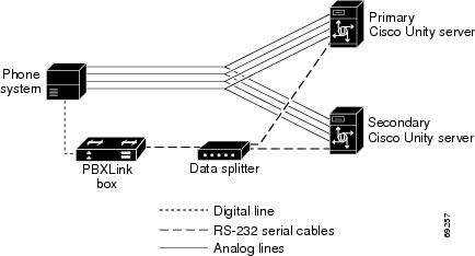
The phone system uses PBXLink boxes to send call information to the two Cisco Unity servers. The analog voice messaging lines from the phone system provide voice connectivity to the Cisco Unity servers. Figure 3 shows the required connections.

Figure 3 Connections Between the Phone System and Cisco Unity Servers

The primary and secondary servers act in the following manner:

When the primary server is operating normally, the secondary server is inactive.

When the primary server becomes inactive, the secondary server becomes active.

When the primary server becomes active again, the secondary server becomes inactive.

Setting Up the Secondary Server for Failover

Do the following procedure to integrate the Cisco Unity secondary server.

To Set Up the Secondary Server for Failover


Step 1 Install a secondary server with the same configuration as the primary server. For installation instructions, refer to the Cisco Unity Installation Guide.

Step 2 Make all voice connections from the phone system to the corresponding ports on both the primary server and the secondary server. For example, connect port 1 from the phone system with port 1 on both the primary and the secondary servers.

Step 3 Connect the cables for the PBXLink boxes on the secondary server as described earlier in this integration guide.

Step 4 Set up the PBXLink boxes as described in the section "Setting up the PBXLink box" earlier in this integration guide.

Step 5 Program the phone system to send call information simultaneously through the digital lines connected to the PBXLink boxes.

Step 6 In the Cisco Unity Administrator of the secondary server, enter the settings on the System > Ports page to match the port settings on the primary server.


Caution In programming the phone system, do not send calls to voice messaging ports in Cisco Unity that cannot answer calls (voice messaging ports that are not set to Answer Calls). For example, if a voice messaging port is set only to Dialout MWI, do not send calls to it.

Step 7 If the automatic failover that occurs when the secondary server receives a call is disabled, skip the remaining steps.

If the automatic failover that occurs when the secondary server receives a call is enabled (the default), on the Windows Start menu of the Cisco Unity server, click Programs > Cisco Unity > Edit Switch Utility.

Step 8 In the Switch Configuration Editor dialog box, click the Edit This Switch Configuration button.

Step 9 In the Switch Configuration dialog box, click the Incoming Calls tab.

Step 10 In the Call Rings field, enter 3 and click OK.

Step 11 Click Exit.

Step 12 For the settings to take effect, exit and restart the Cisco Unity software.


No changes to the hunt group programming on the phone system are necessary.


Dual Phone System Integration


Cisco Unity can be integrated with one each of the following phone systems at the same time:

A traditional, circuit-switched phone system. Any circuit-switched phone system that Cisco Unity integrates with can be used in a dual phone system integration.

Cisco CallManager.

All extensions for subscribers and call handlers must be unique regardless of which phone system a subscriber (or call handler) uses. To transfer calls from one phone system to the other, Cisco Unity must dial the same access codes that a subscriber dials when calling someone on the other phone system.

Dual Phone System Integration Overview

Before doing the following integration steps, confirm that theCisco Unity server is ready for the integration by completing the applicable tasks in the Cisco Unity Installation Guide.

Integration Steps When No Phone Systems Are Installed

Follow these steps to set up the dual phone system integration when no phone systems are installed.

1. Install the circuit-switched phone system.

2. Integrate the circuit-switched phone system and Cisco Unity. See instructions earlier in this integration guide.

3. Install Cisco CallManager.

4. Integrate Cisco CallManager and Cisco Unity. Refer to the applicable Cisco CallManager integration guide, located at http://www.cisco.com/en/US/products/sw/voicesw/ps2237/prod_configuration_guides_list.html.

5. Change the Cisco Unity Administrator settings. See the "Changing Cisco Unity Administrator Settings" section.

Integration Steps When a Circuit-Switched Phone System Is Already Installed

Follow these steps to set up the dual phone system integration when the circuit-switched phone system is already installed and Cisco CallManager is being newly installed.

1. Install Cisco CallManager.

2. Integrate Cisco CallManager and Cisco Unity. See the applicable Cisco CallManager integration guide, located at http://www.cisco.com/en/US/products/sw/voicesw/ps2237/prod_configuration_guides_list.html.

3. Change the Cisco Unity Administrator settings. See the "Changing Cisco Unity Administrator Settings" section.

Integration Steps When Cisco CallManager Is Already Installed

Follow these steps to set up the dual phone system integration when Cisco CallManager is already installed and a circuit-switched phone system is being newly installed.

1. Remove the existing TSP on Cisco Unity. See the "To Remove the Existing TSP" procedure.

2. Install the circuit-switched phone system.

3. Integrate the circuit-switched phone system and Cisco Unity. See the instructions earlier in this integration guide.

4. Reinstall the TSP. See the "To Reinstall the TSP" procedure.

5. Change the Cisco Unity Administrator settings. See the "Changing Cisco Unity Administrator Settings" section.

Requirements

The dual phone system integration supports configurations of the following components:

A Cisco Unity system key with the integration type set to "Multiple integrations" and with the applicable number of voice messaging ports enabled.

The Cisco Unity server set up and Cisco Unity 3.1(x), as described in the Cisco Unity Installation Guide.

A circuit-switched phone system installed and integrated with Cisco Unity. For details, see the instructions earlier in this integration guide. The circuit-switched phone system (including the voice card software used in the integration) must be installed and integrated with Cisco Unity before Cisco CallManager is integrated.

A supported version of Cisco CallManager and the Cisco Unity-CM service provider (TSP) installed and configured. For information about integrating Cisco Unity with Cisco CallManager and the Cisco Unity-CM service provider, see the applicable Cisco CallManager integration guide, located at http://www.cisco.com/en/US/products/sw/voicesw/ps2237/prod_configuration_guides_list.html.

Changing Cisco Unity Administrator Settings

After Cisco Unity is installed and the phone systems have been separately integrated, you need to adjust settings on pages in the Cisco Unity Administrator so that Cisco Unity can work with both phone systems.

Follow these steps to set up the dual phone system integration.

1. Specify settings for the circuit-switched phone system on the System > Switch > Switch page. For details, see the "To Specify Switch Settings for the Circuit-Switched Phone System" procedure.


Caution Specify settings for the circuit-switched phone system before specifying settings for Cisco CallManager. You must proceed in this order, or the integration may not work.

2. Specify settings for Cisco CallManager on the IP Switch page. For details, see the "To specify switch settings for Cisco CallManager" procedure.

3. On the Ports page, assign port ranges to the circuit-switched phone system first, then to Cisco CallManager, and adjust settings for the ports assigned to each phone system. For details, see the "To Modify Voice Port Settings" procedure.

4. Select the phone system that subscribers and call handlers use. For details, see the "To Select Which Phone System Subscribers and Call Handlers Use" procedure.

5. Select the phone system that Cisco Unity uses when dialing out to send message notifications. For details, see the "To Select Which Phone System Cisco Unity Uses for Message Notification" procedure.


Caution If you need to add or remove voice cards or uninstall the voice card software after the dual phone system integration is set up, you must also reinstall the TSP (Cisco Unity-CM service provider). Do not reinstall the TSP until after you have set up the voice cards or reinstalled the voice card software. For more information, see the "Changing the Number of Installed Ports" section.

To Specify Switch Settings for the Circuit-Switched Phone System


Step 1 In the Cisco Unity Administrator, go to the System > Switch > Switch page. The settings for the circuit-switched phone system selected during the Cisco Unity Setup program appear.

Step 2 In the Access Code field, enter the trunk access code that Cisco Unity must dial to transfer calls to Cisco CallManager from the circuit-switched phone system.

The access code is the same number that subscribers on the circuit-switched phone system dial to reach someone on the Cisco CallManager system.

Step 3 Adjust other settings as applicable. For more information about the other settings on the Switch page, refer to the Cisco Unity Administrator Help.

Step 4 Click the Save icon, then click OK in the Warning dialog box.


To specify switch settings for Cisco CallManager


Step 1 Go to System > Switch > IP Switch.

Step 2 In the Set Active Switch Type section, enter values as shown in the following table:

Table 23 Switch Settings 

Switch Parameter
Required Setting

Manufacturer

Cisco

Model

CallManager

Switch PBX software version

3.01 or later

Integration

TAPI


Step 3 Click Set As Active, then click OK in the Warning dialog box.

Step 4 In the Access Code field, enter the trunk access code that Cisco Unity must dial to transfer calls to the circuit-switched phone system from Cisco CallManager.

The access code is the same number that subscribers on Cisco CallManager dial to reach someone on the circuit-switched phone system.

Step 5 Click the Save icon, then click OK in the Warning dialog box.


To Modify Voice Port Settings


Step 1 In the Cisco Unity Administrator, go to the System > Ports page.

Step 2 In the Port Assignments section, indicate the range of ports to be assigned to the circuit-switched phone system. The port range for the circuit-switched phone system begins with 1 and extends to no more than the number of ports that are on the installed voice cards. Do not assign more ports to the circuit-switched phone system than the number of ports on the voice cards.


Caution If you assign fewer voice ports to the circuit-switched phone system than are available on the installed voice cards, you must edit the registry for this port range to take effect. Otherwise, all available voice ports on the voice cards are used in the integration regardless of the Port Assignments settings. For information on editing the registry for the port range, see the appendix "Assigning Dialogic Ports for a Dual Phone System Integration."

Step 3 In the Port Assignments section, indicate the range of ports to be assigned to Cisco CallManager. The port range must begin with the next port after the last port for the circuit-switched phone system. The range for Cisco CallManager must end with the port number of the last port displayed on the Ports page, or the number of licensed voice ports on the system key, whichever is lower. In other words, the number of ports available for Cisco CallManager is the difference between the number of licensed voice ports on the system key and the number of ports assigned to the circuit-switched phone system.

Step 4 Enter an extension for each port.

Step 5 Specify other settings as applicable. For each phone system, confirm that an appropriate number of ports are used to answer calls and to dial out for message waiting indicators (MWIs), message notifications, and Media Master recordings by phone.

Step 6 Click the Save icon.


Caution The port range for each phone system must be set as specified in Step 2 and Step 3 above. If there is a port range mismatch, Cisco Unity will be unable to answer incoming calls and to dial out.

To Select Which Phone System Subscribers and Call Handlers Use

For existing subscriber templates, subscriber accounts, and call handlers, Cisco Unity uses the circuit-switched phone system as its default. Therefore, during the initial setup of the dual phone integration, you will modify only those pages that will be using Cisco CallManager. Note that changes made to subscriber templates do not affect existing subscriber accounts.


Step 1 In Cisco Unity Administrator, go to the applicable page:

Subscribers > Subscriber Template > Profile

Subscribers > Subscribers > Profile

Call Management > Call Handlers > Profile

Step 2 In the Switch list, select the applicable phone system.

Step 3 Adjust other settings as applicable. For more information, refer to the Cisco Unity Administrator Help.


Caution If the Switch setting on the Profile page for the subscriber or call handler does not match the phone system actually used by a subscriber or call handler, Cisco Unity will not be able to transfer calls to or from the subscriber or call handler. Additionally, Cisco Unity will be unable to turn the MWIs for the subscriber on or off and will be unable to reach the extension for the subscriber when recording by phone with Media Master.

To Select Which Phone System Cisco Unity Uses for Message Notification

If subscribers use message notification, you can select which phone system Cisco Unity dials out on when notifying subscribers of new messages. Note that changes made to subscriber templates do not affect existing subscribers.


Step 1 In Cisco Unity Administrator, go to the applicable page:

Subscribers > Subscriber Template > Message Notification

Subscribers > Message Notification

Step 2 For each device, in the Switch list select the phone system that Cisco Unity uses to dial out when notifying subscribers of new messages. Each notification device can be associated with a specific phone system (except for text pagers).

Cisco Unity uses as the default the phone system specified on the Profile page of the subscriber template.

Step 3 Adjust other settings as applicable. For more information, refer to the Cisco Unity Administrator Help.


Caution The selected phone system must have at least one port set to dial out for message notifications on the System > Ports page. If the selected phone system does not have any ports set for this function, notifications will fail.

Changing the Number of Installed Ports

After the dual phone system integration is set up, if you need to add or remove voice cards or uninstall voice card software, follow these steps:

1. Remove the existing TSP. For details, see the "To Remove the Existing TSP" procedure. (In versions earlier than 3.1(1), the Cisco Unity-CM TSP was known as the AV-Cisco TSP.)

2. As applicable, remove or add voice cards, or uninstall and reinstall the voice card software. For information about removing Dialogic voice card software, refer to the chapter about voice cards in the Cisco Unity Installation Guide.

3. Reinstall the TSP after you have set up the voice cards or reinstalled the voice card software. For details, see the "To Reinstall the TSP" procedure.

4. Adjust the port assignments on the System > Ports page. The voice messaging ports must appear in the following order in the list of ports: first are all of the ports connected to the circuit-switched phone system, second are the ports connected to Cisco CallManager.

If you completely remove the circuit-switched phone system, you must adjust the port assignments for Cisco CallManager on the System > Ports page, after the voice cards and voice card software used in the integration with the circuit-switched phone system have been removed.

To Remove the Existing TSP


Step 1 On the Cisco Unity server, log on to Windows as an administrator.

Step 2 Stop Cisco Unity (right-click the Cisco Unity icon in the system tray, then click Stop Unity).

Step 3 On the Windows Start menu, click Settings > Control Panel > Add/Remove Programs.

Step 4 In the list, click Cisco Unity-CM TSP.


Note In versions earlier than 3.1(1), the Cisco Unity-CM TSP was known as the AV-Cisco TSP.


Step 5 Click Remove.

Step 6 Click Yes.

Step 7 Close Control Panel.


To Reinstall the TSP


Step 1 On the Cisco Unity server, log on to Windows as an administrator.

Step 2 On the Windows Start menu, click Settings > Control Panel.

Step 3 Double-click Phone and Modem Options. The Phone and Modem Options dialog box appears.

Step 4 Click the Advanced tab.

Step 5 Click Add. The Add Driver dialog box appears.

Step 6 Click Cisco Unity-CM Service Provider, then click Add. A dialog box appears confirming the installation of the TSP.

Step 7 Click OK to close the dialog box.

Step 8 Click Close to close the Phone and Modem Options dialog box.

Step 9 Close Control Panel.

Step 10 Restart the Cisco Unity server.


Appendix: Remapping Extension Numbers


About the Remapping Feature

The extension remapping feature lets you convert to the extensions of your choice the calling numbers and forwarding numbers of calls handled by Cisco Unity. This feature is useful, for example, when the phone system cannot map multiple extension numbers on a subscriber phone to a single Inbox.

Remapping can change one or both of the following extension numbers in a call:

Calling number (the number from which a call originates). For example, Cisco Unity changes the calling number of calls so that the caller ID appears to be a different extension than the one that actually placed the call.

Forwarding number (the number that a call is going to). For example, unanswered calls to all line extensions on a single phone can be forwarded to the Inbox of a single subscriber; or unanswered calls to phones not assigned to subscribers can be forwarded to the Inbox of a supervisor.

Setting Up Cisco Unity to Remap Extension Numbers

This section includes a procedure for enabling the remapping feature. You can create multiple files in either or both of two directories:

In the Calling directory, one or more .exm files remap caller ID numbers.

In the Forwarding directory, one or more .exm files remap numbers that Cisco Unity provides with calls it forwards.

When you create remapping instructions in a .exm file in a directory, Cisco Unity remaps only the type of extension number that the directory is named for. For example, if you want to remap only the extensions that Cisco Unity provides with calls it forwards, you enter the instructions in a .exm file in the Forwarding directory; in this circumstance, the Calling directory needs no .exm file.

In each directory, you can have several .exm files with different file names but with the same .exm extension. This helps you to organize the remapping information. For example, you could create two files in a directory: Ports_1-12.exm and Ports_13-24.exm. Cisco Unity reads all files that have the .exm extension in these directories.

To Remap Extension Numbers


Step 1 On the Cisco Unity server, browse to the CommServer\IntLib\ExtensionMapping directory. In this directory is the file Sample.txt and two more directories: Calling and Forwarding.

Step 2 To remap calling numbers, go to the Calling directory.

Step 3 In a text editor application, create a new .exm file, or open a currently existing .exm file.

For an example, open the file Sample.txt in the CommServer\IntLib\ExtensionMapping directory.

Step 4 Enter [Range] and press Return to create a section for indicating which voice messaging ports will be monitored for remapping calls.

A .exm file can have only one [Range] section.

Step 5 Enter ports= followed by the numbers of the voice messaging ports, separated by commas. Ranges are designated by a hyphen (-) without spaces. To monitor all voice messaging ports, enter ports=* on this line. Then press Return.

For example, you might enter:

ports=1,2,5-34

Step 6 To create a section for the remapping rules, press Return, enter [Number Mappings], and then press Return.

A .exm file can have only one [Number Mappings] section.

Step 7 Enter one remapping rule on the line, and then press Return.

See the remapping rule examples in the following "Syntax and Examples" section. The rule format is:

<original number>, <new number>

The rules cannot include spaces between digits. However, the numbers must be separated by a comma and a single space. Wildcard characters cannot appear at the beginning of a number.

Step 8 For all remaining rules, repeat Step 7.

Step 9 Save and close the .exm file.

Step 10 To remap forwarding numbers, browse to the directory CommServer\IntLib\ExtensionMapping\Forwarding.

Step 11 Repeat Step 3 through Step 9 to remap forwarding numbers.

Step 12 For extension remapping to take effect, restart the Cisco Unity software.


Syntax and Examples

Table 0-24 shows the wildcard characters you can use in the .exm files.

Table 0-24 Wildcard Characters 

Wildcard
Result

*

Matches zero or more digits.

?

Matches exactly one digit. Use ? as a placeholder for a single digit.


Table 0-25 gives examples for the syntax and results of rules in the .exm files.

Table 0-25 Syntax Examples 

Rule
Original Number
New Number

2189, 1189

3189, 1189

4189, 1189

2189

3189

4189

1189

1189

1189

2???, 1???

2189

2291

1189

1291

3???, 1???

3189

3291

1189

1291

8???, 61???

8000

8765

61000

61765

123*, 44*

12300

12385

4400

4485


Cisco Unity executes rules in the order they appear in the .exm file. For example, the .exm file might contain the following rules:

1234, 1189
3189, 1189
4189, 1189
123?, 8891

The extension 1234 would be remapped to 1189 while extensions 1233 and 1235 would be remapped to 8891, because the rule mapping 1234 appears earlier.

An .exm file might contain the following:

[Range]
ports=1,2,5-34

[Number Mappings]
2189, 1189
3189, 1189
4189, 1189
8???, 9???


Appendix: Assigning Dialogic Ports for a Dual Phone System Integration


In a dual phone system integration, Cisco Unity assigns a voice messaging port to the traditional, circuit-switched phone system for every port available on the installed voice cards before assigning voice messaging ports to Cisco CallManager. The result is that Cisco Unity may not have enough voice messaging ports remaining to assign to Cisco CallManager.

The maximum number of voice messaging ports are assigned to the circuit-switched phone system regardless of the settings on the Ports page in the System Administrator.

For example, a dual phone system integration might have the following configuration:

A circuit-switched phone system has a four-port voice card installed.

Cisco CallManager has six Voice Mail ports set up.

The Cisco Unity server has a system key enabled for a total of eight ports.

The Ports page on System Administrator indicates that Ports 1 and 2 are assigned to the circuit-switched phone system and Ports 3 through 8 are assigned to Cisco CallManager.

Even so, Ports 1 through 4 (the total voice card ports) will be assigned to the circuit-switched phone system, and Ports 5 through 6 will be assigned to Cisco CallManager.

If you want to assign fewer than the total number of voice card ports to the circuit-switched phone system, you must first set the Port assignments on the Ports page of the System Administrator, then do the following procedure.

To Set the Port Assignments in the Registry


Step 1 On the Cisco Unity server, on the Windows Start menu, click Run.

Step 2 In the Open field, enter Regedit and press Enter. The Registry Editor appears.


Caution Changing the wrong registry key or entering an incorrect value can cause the server to malfunction. Before you edit the registry, confirm that you know how to restore it if a problem occurs. (Refer to the "Restoring" topics in Registry Editor Help.) Note that a typical backup of the Cisco Unity server does not back up the registry. Also note that for a Cisco Unity failover system, registry changes on one Cisco Unity server must be made manually on the other Cisco Unity server, because registry changes are not replicated. If you have any questions about changing registry key settings, contact Cisco TAC.

Step 3 If you do not have a current backup of the registry, click Registry > Export Registry File, and save the registry settings to a file.

Step 4 Expand the key HKEY_LOCAL_MACHINE\Software\ActiveVoice\MIU\1.0\Initialization\ServiceProvider <x>, where <x> is a number.

You will find several subkeys with this name.

Step 5 Locate the subkey in which the value Service Provider Name is D41MT.TSP.

Step 6 In this subkey, in the Edit menu click New > DWORD Value. A new value appears in the subkey.

Step 7 Enter the name DeviceID Lower Bound and press Enter.

Step 8 Double-click the DeviceID Lower Bound value. The Edit DWORD Value dialog box appears.

Step 9 In the Value Data field, enter 1 and click OK.

Step 10 in the Edit menu click New > DWORD Value. A new value appears in the subkey.

Step 11 Enter the name DeviceID Upper Bound and press Enter.

Step 12 Double-click the DeviceID Upper Bound value. The Edit DWORD Value dialog box appears.

Step 13 In the Value Data field, enter the number of Dialogic ports you want to assign and click OK.

Step 14 Close the Registry Editor.

Step 15 For the settings to take effect, exit and restart the Cisco Unity software.


Appendix: Documentation and Technical Assistance


Conventions

The Avaya Definity Gx/PBXLink Integration Guide for Cisco Unity 3.1 uses the following conventions.

Table 26 Avaya Definity Gx/PBXLink Integration Guide for Cisco Unity 3.1 Conventions 

Convention
Description

boldfaced text

Boldfaced text is used for:

Key and button names. (Example: Click OK.)

Information that you enter. (Example: Enter Administrator in the User Name box.)

< >

(angle brackets)

Angle brackets are used around parameters for which you supply a value. (Example: In the Command Prompt window, enter ping <IP address>.)

-

(hyphen)

Hyphens separate keys that must be pressed simultaneously. (Example: Press Ctrl-Alt-Delete.)

>

(right angle
bracket)

A right angle bracket is used to separate selections that you make:

On menus. (Example: On the Windows Start menu, click Settings > Control Panel > Phone and Modem Options.)

In the navigation bar of the Cisco Unity Administrator. (Example: Go to the System > Configuration > Settings page.)

[x]

(square brackets)

Square brackets enclose an optional element (keyword or argument). (Example: [reg-e164])

[x | y]

(vertical line)

Square brackets enclosing keywords or arguments separated by a vertical line indicate an optional choice. (Example: [transport tcp | transport udp])


The Avaya Definity Gx/PBXLink Integration Guide for Cisco Unity 3.1 also uses the following conventions:


Note Means reader take note. Notes contain helpful suggestions or references to material not covered in the document.


Caution Means reader be careful. In this situation, you might do something that could result in equipment damage or loss of data.

For descriptions and URLs of Cisco Unity documentation on Cisco.com, refer to About Cisco Unity Documentation. The document is shipped with Cisco Unity and is available at http://www.cisco.com/univercd/cc/td/doc/product/voice/c_unity/about/aboutdoc.htm.

Obtaining Documentation

Cisco documentation and additional literature are available on Cisco.com. Cisco also provides several ways to obtain technical assistance and other technical resources. These sections explain how to obtain technical information from Cisco Systems.

Cisco.com

You can access the most current Cisco documentation at this URL:

http://www.cisco.com/univercd/home/home.htm

You can access the Cisco website at this URL:

http://www.cisco.com

You can access international Cisco websites at this URL:

http://www.cisco.com/public/countries_languages.shtml

Documentation DVD

Cisco documentation and additional literature are available in a Documentation DVD package, which may have shipped with your product. The Documentation DVD is updated regularly and may be more current than printed documentation. The Documentation DVD package is available as a single unit.

Registered Cisco.com users (Cisco direct customers) can order a Cisco Documentation DVD (product number DOC-DOCDVD=) from the Ordering tool or Cisco Marketplace.

Cisco Ordering tool:

http://www.cisco.com/en/US/partner/ordering/

Cisco Marketplace:

http://www.cisco.com/go/marketplace/

Ordering Documentation

You can find instructions for ordering documentation at this URL:

http://www.cisco.com/univercd/cc/td/doc/es_inpck/pdi.htm

You can order Cisco documentation in these ways:

Registered Cisco.com users (Cisco direct customers) can order Cisco product documentation from the Ordering tool:

http://www.cisco.com/en/US/partner/ordering/

Nonregistered Cisco.com users can order documentation through a local account representative by calling Cisco Systems Corporate Headquarters (California, USA) at 408 526-7208 or, elsewhere in North America, by calling 1 800 553-NETS (6387).

Documentation Feedback

You can send comments about technical documentation to bug-doc@cisco.com.

You can submit comments by using the response card (if present) behind the front cover of your document or by writing to the following address:

Cisco Systems
Attn: Customer Document Ordering
170 West Tasman Drive
San Jose, CA 95134-9883

We appreciate your comments.

Cisco Product Security Overview

Cisco provides a free online Security Vulnerability Policy portal at this URL:

http://www.cisco.com/en/US/products/products_security_vulnerability_policy.html

From this site, you can perform these tasks:

Report security vulnerabilities in Cisco products.

Obtain assistance with security incidents that involve Cisco products.

Register to receive security information from Cisco.

A current list of security advisories and notices for Cisco products is available at this URL:

http://www.cisco.com/go/psirt

If you prefer to see advisories and notices as they are updated in real time, you can access a Product Security Incident Response Team Really Simple Syndication (PSIRT RSS) feed from this URL:

http://www.cisco.com/en/US/products/products_psirt_rss_feed.html

Reporting Security Problems in Cisco Products

Cisco is committed to delivering secure products. We test our products internally before we release them, and we strive to correct all vulnerabilities quickly. If you think that you might have identified a vulnerability in a Cisco product, contact PSIRT:

Emergencies — security-alert@cisco.com

Nonemergencies — psirt@cisco.com


Tip We encourage you to use Pretty Good Privacy (PGP) or a compatible product to encrypt any sensitive information that you send to Cisco. PSIRT can work from encrypted information that is compatible with PGP versions 2.x through 8.x.

Never use a revoked or an expired encryption key. The correct public key to use in your correspondence with PSIRT is the one that has the most recent creation date in this public key server list:

http://pgp.mit.edu:11371/pks/lookup?search=psirt%40cisco.com&op=index&exact=on


In an emergency, you can also reach PSIRT by telephone:

1 877 228-7302

1 408 525-6532

Obtaining Technical Assistance

For all customers, partners, resellers, and distributors who hold valid Cisco service contracts, Cisco Technical Support provides 24-hour-a-day, award-winning technical assistance. The Cisco Technical Support Website on Cisco.com features extensive online support resources. In addition, Cisco Technical Assistance Center (TAC) engineers provide telephone support. If you do not hold a valid Cisco service contract, contact your reseller.

Cisco Technical Support Website

The Cisco Technical Support Website provides online documents and tools for troubleshooting and resolving technical issues with Cisco products and technologies. The website is available 24 hours a day, 365 days a year, at this URL:

http://www.cisco.com/techsupport

Access to all tools on the Cisco Technical Support Website requires a Cisco.com user ID and password. If you have a valid service contract but do not have a user ID or password, you can register at this URL:

http://tools.cisco.com/RPF/register/register.do


Note Use the Cisco Product Identification (CPI) tool to locate your product serial number before submitting a web or phone request for service. You can access the CPI tool from the Cisco Technical Support Website by clicking the Tools & Resources link under Documentation & Tools. Choose Cisco Product Identification Tool from the Alphabetical Index drop-down list, or click the Cisco Product Identification Tool link under Alerts & RMAs. The CPI tool offers three search options: by product ID or model name; by tree view; or for certain products, by copying and pasting show command output. Search results show an illustration of your product with the serial number label location highlighted. Locate the serial number label on your product and record the information before placing a service call.


Submitting a Service Request

Using the online TAC Service Request Tool is the fastest way to open S3 and S4 service requests. (S3 and S4 service requests are those in which your network is minimally impaired or for which you require product information.) After you describe your situation, the TAC Service Request Tool provides recommended solutions. If your issue is not resolved using the recommended resources, your service request is assigned to a Cisco TAC engineer. The TAC Service Request Tool is located at this URL:

http://www.cisco.com/techsupport/servicerequest

For S1 or S2 service requests or if you do not have Internet access, contact the Cisco TAC by telephone. (S1 or S2 service requests are those in which your production network is down or severely degraded.) Cisco TAC engineers are assigned immediately to S1 and S2 service requests to help keep your business operations running smoothly.

To open a service request by telephone, use one of the following numbers:

Asia-Pacific: +61 2 8446 7411 (Australia: 1 800 805 227)
EMEA: +32 2 704 55 55
USA: 1 800 553-2447

For a complete list of Cisco TAC contacts, go to this URL:

http://www.cisco.com/techsupport/contacts

Definitions of Service Request Severity

To ensure that all service requests are reported in a standard format, Cisco has established severity definitions.

Severity 1 (S1)—Your network is "down," or there is a critical impact to your business operations. You and Cisco will commit all necessary resources around the clock to resolve the situation.

Severity 2 (S2)—Operation of an existing network is severely degraded, or significant aspects of your business operation are negatively affected by inadequate performance of Cisco products. You and Cisco will commit full-time resources during normal business hours to resolve the situation.

Severity 3 (S3)—Operational performance of your network is impaired, but most business operations remain functional. You and Cisco will commit resources during normal business hours to restore service to satisfactory levels.

Severity 4 (S4)—You require information or assistance with Cisco product capabilities, installation, or configuration. There is little or no effect on your business operations.

Obtaining Additional Publications and Information

Information about Cisco products, technologies, and network solutions is available from various online and printed sources.

Cisco Marketplace provides a variety of Cisco books, reference guides, and logo merchandise. Visit Cisco Marketplace, the company store, at this URL:

http://www.cisco.com/go/marketplace/

Cisco Press publishes a wide range of general networking, training and certification titles. Both new and experienced users will benefit from these publications. For current Cisco Press titles and other information, go to Cisco Press at this URL:

http://www.ciscopress.com

Packet magazine is the Cisco Systems technical user magazine for maximizing Internet and networking investments. Each quarter, Packet delivers coverage of the latest industry trends, technology breakthroughs, and Cisco products and solutions, as well as network deployment and troubleshooting tips, configuration examples, customer case studies, certification and training information, and links to scores of in-depth online resources. You can access Packet magazine at this URL:

http://www.cisco.com/packet

iQ Magazine is the quarterly publication from Cisco Systems designed to help growing companies learn how they can use technology to increase revenue, streamline their business, and expand services. The publication identifies the challenges facing these companies and the technologies to help solve them, using real-world case studies and business strategies to help readers make sound technology investment decisions. You can access iQ Magazine at this URL:

http://www.cisco.com/go/iqmagazine

Internet Protocol Journal is a quarterly journal published by Cisco Systems for engineering professionals involved in designing, developing, and operating public and private internets and intranets. You can access the Internet Protocol Journal at this URL:

http://www.cisco.com/ipj

World-class networking training is available from Cisco. You can view current offerings at this URL:

http://www.cisco.com/en/US/learning/index.html


[an error occurred while processing this directive]