Intecom E14 Millennium Serial Integration Guide for Cisco Unity 3.0
Intecom E14 Millennium Serial Integration

Table Of Contents

Intecom E14 Millennium Serial Integration

Integration Overview

Integration Steps

Requirements

Integration Description

Integration Features

Programming the Phone System

Configuring Cisco Unity for the Integration

Testing the Integration


Intecom E14 Millennium Serial Integration


Integration Overview

Before performing the following integration steps, confirm that the Cisco Unity server is ready for the integration by completing the appropriate tasks in Chapters 1 through 3 of the Cisco Unity Installation Guide.

Integration Steps

Follow these steps to set up this integration.

1. Review the system and equipment requirements to confirm that all phone system and Cisco Unity server requirements have been met. See the "Requirements" section.

2. Program the phone system and extensions. See the "Programming the Phone System" section.

3. Configure Cisco Unity for the integration. See the "Configuring Cisco Unity for the Integration" section.

4. Test the integration. See the "Testing the Integration" section.

Requirements

The Intecom E14 Millennium integration supports configurations of the following components:

Phone System

Intecom E14 Millennium

Software version 11.2 or later

A port on the ITE line card connected with analog lines to a PDI-1000/DCE, which in turn is connected to a serial port (COM1 is the default) on the Unity server with an RS-232 serial cable

A T1/IXL card installed in the Interface Shelf, connected to the voice cards in the Cisco Unity server

The phone system ready for the integration as described in the installation guide for the phone system

Cisco Unity Server

The Dialogic® D/240PCI-T1 voice card installed

Cisco Unity installed and ready for the integration as described in the Cisco Unity Installation Guide

A system key that enables the integration and the appropriate number of voice messaging ports

An available serial port (COM1 is the default)

Integration Description

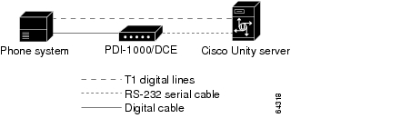
The Intecom E14 Millennium integration uses a data link, which consists of a digital line, a PDI-1000/DCE, and an RS-232 serial cable connecting the phone system and the Cisco Unity server. The T1 voice messaging lines from the phone system connect to the voice cards in the Cisco Unity server. The following illustration shows the required connections.

Figure 1-1 Connections Between the Phone System and Cisco Unity

The phone system sends the following information through the data link:

The extension of the called party

The reason for the forward (the extension is busy, does not answer, or is set to forward all calls)

The extension of the calling party (for internal calls) or the phone number of the calling party (if it is an external call and the system uses caller ID)

Cisco Unity uses this information to answer the call appropriately. For example, a call forwarded to Cisco Unity is answered with the personal greeting of the subscriber. If the phone system routes the call to Cisco Unity without this information, Cisco Unity answers with the opening greeting.

Integration Features

The Intecom E14 Millennium integration with Cisco Unity provides the following features:

Call forward to personal greeting

When an incoming call is routed to an unanswered or busy extension, the call is forwarded to the voice mail of the subscriber. The caller then hears the personal greeting of the subscriber and can leave a message.

Caller ID

Cisco Unity receives caller ID information from the phone system (if available). This information appears in the subject line of the message in the desktop messaging application.

Easy message access

A subscriber can retrieve messages without entering an ID. Cisco Unity identifies a subscriber based on the extension from which the call originated. A password may be required.

Identified subscriber messaging

Cisco Unity automatically identifies a subscriber who leaves a message during a forwarded internal call, based on the extension from which the call originated.

Message waiting indication

When a message is waiting for a subscriber, Cisco Unity notifies the phone system to activate the message waiting indicator (MWI) on the subscriber's extension (a lamp or a stutter dial tone).


Programming the Phone System

If you use programming options other than those supplied in the following procedure, the performance of the integration may be affected.

To program the phone system


Step 1 Create a TTYP group for the PDI-1000/DCE interface. Use the following settings:

Asynchronous line type

Bisync protocol

ASCII coding

1200 baud

Even parity

1 stop bit

7 data bits

Step 2 Assign an ITE data port for the PDI-1000/DCE interface to the TTYP group created in Step 1. Make sure that the port type for this ITE data port is DPRT.

Step 3 Use the ILK subcommand of the UTIL command to link this ITE data port to the PBX MCU.

For some versions of the Intecom phone system, use the NAIL command to perform this step.

Step 4 Define a two-way universal trunk group for the voice messaging ports. The parameters used for testing the integration were as follows:

** TRUNK GROUP DEFINITION      05/09/37  19:34:51
***...TRUNK GROUP........................37
***...TRUNK GROUP TYPE...................UNIVERSAL
TCI...TRUNK CLASS IDENTIFICATION.........FX
UGP...USER GROUP NUMBER..................1
VTT...VOICE TRUNK TRANSFER ENABLED.......YES
CDT...TRANSFER COLLECT DIGIT TABLE #.....NONE
DCS...DEFAULT CLASS OF SERVICE...........1
CNC...NATIONAL CALLING PARTY # CONTENTS..NONE
DCP...DISPLAY CALLING PARTY NUMBER.......YES
PND...PRIVATE NETWORK....................YES
***...LANmark PRI TRUNK GROUP............NO
ITY...INTEMAIL TYPE......................SMDI - FIXED 7 DIGIT
IST...DOES InteMail SUPERVISE TRANSFERS?.YES
MCT...METHOD TO CANCEL InteMail TRANSFER.FLASH
IML...InteMail USER ID LENGTH............6
IIN...INTEMAIL INTERFACE NUMBER..........1
VNP...InteMail NUMBER FORMAT.............DIRN
OAM...OAI ASSOCIATED MEMBER..............NO
BTG...BROADCAST TRUNK GROUP..............NO
TCM...TRAVELING CLASSMARK................NO
FTH...FAILURE THRESHOLD..................3
RDT...RESEIZE DELAY TIME............MSEC:50
CHT...TRUNK MONITOR MINIMUM HOLD TIME....0
DET...DISTANT END RELEASE TIME.......SEC:60
DCT...DATA CALLS ALLOWED.................NO
SWM...SEIZE WHEN MOS.....................YES
TCH...TRUNK CALL HANDLING................EXTERNAL
NDS...DISCONNECT SUPERVISION.............YES
IGG...IGNORE GLARE.......................NO
GDT...GLARE DETECT TIME.............MSEC:100
XFT...DISTANT IBX ALLOWS FEATURE TRANSP..NO
DPT...DTMF PASSTHROUGH TIMING INDEX......NONE
......TRUNK DIRECTION....................BOTH WAYS
 *** INCOMING PARAMETERS
STY...INCOMING CALL ORIGINATION TYPE.....T1 OFF PREM.OPX (OFF PREMISE)
TYP...INCOMING TRUNK TYPE................DIALED
ICM...INCOMING CALL MESSAGE #............NONE
IDS...INCOMING DIGIT SEQUENCE............DESTINATION NUMBER ONLY
IRD...RESPONSE TO DESTINATION NUMBER.....NONE
IRC...RESPONSE TO CALLING PARTY NUMBER...NONE
IIT...INCOMING INFO DIGIT TYPE/LENGTH....NONE
BGP...ANNOUNCEMENT BROADCAST TRUNK GROUP.NONE
APA...TRUNK GROUP AUTHORIZATION TYPE.....NONE
PVA...PRE-VALIDATE AUTHORIZATION CODE....NO
RSC...RESET COUNT........................1
LVL...PREDEFINED LEVEL CODE..............NONE
TNE...TONE TABLE ENTRY NUMBER............NONE
MOD...INCOMING DIAL MODE.................DTMF
RGF...DTMF RECEIVER GROUP................52
TOO...TIMEOUT TO ATTENDANT...............NO
MCL...MULTIPLE CALLING ALLOWED...........NO
RAC...REUSE AUTH FOR MULT. CALLS.........NO
GAC...GROUP AUTH REQUIRED FOR TRUNKS.....NO
SAC...SYSTEM ACCESS CODE.................NONE
CWR...CALLWAIT RINGBACK..................NO
UCT...TRUNK UPDATE CDR ON TRANSFER.......ALL
CPT...CALL PROGRESSING TONES:............IBX PROVIDED
RIO...RESPONSE TO INCOMING ORIGINATION...SEIZE IMMED.
TCT...STATION CALL RESTRICTION ENABLED...NO
8NC...800 TO 4D SPEED NUMBER CONVERSION..NO
 *** OUTGOING PARAMETERS
MSG...MODEM SIGNALLING...................YES
TXA...DIRECT TGRP SELECT ALLOWED.........YES
ATG...ANNOUNCEMENT TRUNK GROUP...........NO
SLC...TRUNK SELECTION....................TOP DOWN
ICA...INTER-LATA CARRIER.................10XXX
CPN...CALLING PARTY NUMBER...............DO NOT SEND

Step 5 Configure the T1 cards to be connected to Cisco Unity for the following:

Internal clocking

AMI line coding

D4 framing

Step 6 Create appropriate routing for access to the voice mail trunk group.

Make sure that the Cisco Unity subscribers are assigned feature options and class of service options that accommodate voice mail.

Step 7 Program each phone to forward calls to the pilot number assigned to the voice messaging ports, based on one of the following Cisco Unity call transfer types.

Table 1-1 Call Transfer Types

Transfer type
Usage

Release transfer
(blind transfer)

Program the phone to forward calls to the pilot number when:

The extension is busy

The call is not answered

Supervised transfer

Program the phone to forward calls to the pilot number only when the call is not answered. Confirm that call forwarding is disabled when the extension is busy.


Configuring Cisco Unity for the Integration

After ensuring that the Cisco Unity server is ready for the integration by completing the appropriate tasks in Chapters 1 through 3 of the Cisco Unity Installation Guide, perform the following procedures to confirm that the integration is enabled and to enter the port settings.

To confirm that the integration is enabled


Step 1 On the Cisco Unity server, go to the Cisco Unity Administrator by doing one of the following:

In Internet Explorer, go to http://<server name>/web/sa.

Double-click the desktop shortcut to the Cisco Unity Administrator.

Step 2 Go to System > Licensing > Licensed Features.

Step 3 In the Integration field, confirm that the setting is Serial for a single phone system integration or Multiple Integrations for a dual phone system integration.

Step 4 If the setting is not Serial or Multiple Integrations, contact your sales representative for the necessary system key.

Step 5 Go to System > Switch. Confirm that the settings match those in the following table. If the settings are incorrect, integration features may not be enabled.

Table 1-2 Switch Settings

Switch Parameter
Required Setting

Manufacturer

Intecom

Model

E14 Millennium

Switch PBX Software Version

All

Integration

Serial


Step 6 Click the Save icon.


To enter port settings


Step 1 In the Cisco Unity Administrator, go to System > Ports.

Step 2 Select a port in the table.

Step 3 Indicate the settings for the port.

For a hunt group, use the first voice-messaging ports for incoming calls and the last ports to dial out. This helps minimize the possibility of a collision, in which an incoming call arrives on a port at the same time that Cisco Unity takes the port off-hook to dial out.

Step 4 Type the extension for the port.

Step 5 Repeat Steps 2 through 4 for the remaining ports.

Step 6 Click the Save icon.

Step 7 For the settings to take effect, exit and restart the Cisco Unity software. For more information, see Appendix A, "Exiting and Starting the Cisco Unity Software and Server."


Testing the Integration

To test whether Cisco Unity and the phone system are integrated correctly, perform the procedures in the order listed.

If any of the steps indicates a failure, see the following documentation as appropriate:

The installation guide for the phone system

Cisco Unity Troubleshooting Guide

This integration guide

To set up the test configuration


Step 1 Set up two test extensions (Phone 1 and Phone 2) on the same phone system that Cisco Unity is connected to.

Step 2 Set Phone 1 to forward calls to the Cisco Unity pilot number when calls are not answered.

Step 3 In the Cisco Unity Administrator, go to Subscribers > Subscribers > Profile.

If Example Subscriber is not displayed, click the Find icon (the magnifying glass) in the title bar, then click Find, and select Example Subscriber in the list that appears.

Step 4 In the Extension field, enter the extension of Phone 1.

Step 5 Click the Save icon.

Step 6 In the navigation bar, click Call Transfer to go to Subscribers > Subscribers > Call Transfer for Example Subscriber.

For more information on transfer settings, refer to the "Subscriber Template Call Transfer Settings" section in the Help for the Cisco Unity Administrator.

Step 7 Under Transfer Incoming Calls, click Yes, Ring Subscriber's Extension, and confirm that the extension number is for Phone 1.

Step 8 Under Transfer Type, click Release to Switch.

Step 9 Click the Save icon.

Step 10 In the navigation bar, click Messages to go to Subscribers > Subscribers > Messages for Example Subscriber.

Step 11 Under Message Waiting Indicators (MWIs), check Use MWI for Message Notification.

Step 12 In the Extension field, enter x.

Step 13 Click the Save icon.

Step 14 Open the Status Monitor by doing one of the following:

In Internet Explorer, go to http://<server name>/web/sm.

Double-click the desktop shortcut to the Status Monitor.

In the Windows systray, right-click the Cisco Unity icon and click Status Monitor.


To test an external call with release transfer


Step 1 From Phone 2, enter the access code necessary to get an outside line, then enter the number outside callers use to dial directly to Cisco Unity.

Step 2 On the Status Monitor, note the port that handles this call.

Step 3 When you hear the opening greeting, enter the extension for Phone 1. Hearing the opening greeting means that the port is configured correctly.

Step 4 Confirm that Phone 1 rings and that you hear a ringback tone on Phone 2. Hearing a ringback tone means that Cisco Unity released the call and transferred it to Phone 1.

Step 5 Do not answer Phone 1, and confirm that the state of the port handling the call changes to "Idle." This state means that release transfer succeeds.

Step 6 Confirm that, after the number of rings that the phone system is set to wait, the call is forwarded to Cisco Unity and that you hear the greeting for Example Subscriber. Hearing the greeting means that the phone system forwarded the unanswered call and the call-forward information to Cisco Unity, which correctly interpreted the information.

Step 7 On the Status Monitor, note the port that handles this call.

Step 8 Leave a message for Example Subscriber and hang up Phone 2.

Step 9 On the Status Monitor, confirm that the state of the port handling the call changes to "Idle." This state means that the port was successfully released when the call ended.

Step 10 Confirm that the MWI on Phone 1 is activated. The activated MWI means that the phone system and Cisco Unity are successfully integrated for turning on MWIs.


To test an internal call with release transfer


Step 1 From Phone 1, enter the internal pilot number for Cisco Unity.

Step 2 When asked for your password, enter 12345. Hearing the request for your password means that the phone system sent the necessary call information to Cisco Unity, which correctly interpreted the information.

Step 3 Confirm that you hear the recorded voice name for Example Subscriber. Hearing the voice name means that Cisco Unity correctly identified the subscriber by the extension.

Step 4 When asked whether you want to listen to your messages, press 1.

Step 5 After listening to the message, press 3 to delete the message.

Step 6 Confirm that the MWI on Phone 1 is deactivated. The deactivated MWI means that the phone system and Cisco Unity are successfully integrated for turning off MWIs.

Step 7 Hang up Phone 1.

Step 8 On the Status Monitor, confirm that the state of the port handling the call changes to "Idle." This state means that the port was successfully released when the call ended.


To set up supervised transfer on Cisco Unity


Step 1 In the Cisco Unity Administrator, go to Subscribers > Subscribers > Call Transfer.

If Example Subscriber is not displayed, click the Find icon (the magnifying glass) in the title bar, then click Find, and select Example Subscriber in the list that appears.

For more information on transfer settings, refer to the "Subscriber Template Call Transfer Settings" section in the Help for the Cisco Unity Administrator.

Step 2 Under Transfer Type, click Supervise Transfer.

Step 3 Set the Rings to Wait For field to 3.

Step 4 Click the Save icon.


To test supervised transfer


Step 1 From Phone 2, enter the access code necessary to get an outside line, then enter the number outside callers use to dial directly to Cisco Unity.

Step 2 On the Status Monitor, note the port that handles this call.

Step 3 When you hear the opening greeting, enter the extension for Phone 1. Hearing the opening greeting means that the port is configured correctly.

Step 4 Confirm that Phone 1 rings and that you do not hear a ringback tone on Phone 2. Instead, you should hear the indication your phone system uses to mean that the call is on hold (for example, music or beeps).

Step 5 Do not answer Phone 1, and confirm that the state of the port handling the call remains "Busy." This state and hearing an indication that you are on hold mean that Cisco Unity is supervising the transfer.

Step 6 Confirm that, after three rings, you hear the greeting for Example Subscriber. Hearing the greeting means that Cisco Unity successfully recalled the supervised-transfer call.

Step 7 During the greeting, hang up Phone 2.

Step 8 On the Status Monitor, confirm that the state of the port handling the call changes to "Idle." This state means that the port was successfully released when the call ended.


To return Example Subscriber to the default settings


Step 1 In the Cisco Unity Administrator, go to Subscribers > Subscribers > Call Transfer.

If Example Subscriber is not displayed, click the Find icon (the magnifying glass) in the title bar, then click Find, and select Example Subscriber in the list that appears.

Step 2 Under Transfer Incoming Calls, click No (Send Directly to Subscriber's Greeting).

Step 3 In the navigation bar, click Profile to go to Subscribers > Subscribers > Profile.

Step 4 In the Extension field, enter 99990.

Step 5 Click the Save icon.

Step 6 In the navigation bar, click Messages to go to Subscribers > Subscribers > Messages for Example Subscriber.

Step 7 Under Message Waiting Indicators (MWIs), uncheck Use MWI for Message Notification.

Step 8 Click the Save icon.