-
Cisco Unified CallManager System Guide, Release 4.2(1)
-
Index
-
Preface
-
Introduction
-
Cisco IP Telephony Overview
-
System Configuration Overview
-
Multilevel Administration
-
System-Level Configuration Settings
-
Clustering
-
Redundancy
-
Call Admission Control
-
Cisco TFTP
-
Device Support
-
Services
-
Auto-Registration
-
Partitions and Calling Search Spaces
-
Time-of-Day Routing
-
Understanding Route Plans
-
Application Dial Rules Overview
-
Understanding the Directory
-
Managing User Directory Information
-
Media Resource Management
-
Annunciator
-
Conference Bridges
-
Transcoders
-
Music On Hold
-
Media Termination Points
-
Cisco DSP Resources for Transcoding, Conferencing, and MTP
-
Voice Mail Connectivity to Cisco CallManager
-
SMDI Voice Mail Integration
-
Cisco Unity Messaging Integration
-
Cisco DPA Integration
-
Call Park and Directed Call Park
-
Call Pickup
-
Cisco IP Phone Services
-
Cisco CallManager Extension Mobility and Phone Login Features
-
Cisco CallManager Attendant Console
-
Cisco IP Manager Assistant
-
Understanding Cisco CallManager Voice Gateways
-
Understanding IP Telephony Protocols
-
Understanding Session Initiation Protocol (SIP)
-
Understanding Cisco CallManager Trunk Types
-
Cisco IP Phones
-
Understanding Video Telephony
-
Computer Telephony Integration (Revised 01/08/2007)
-
Cisco ATA 186 and Cisco ATA 188
-
Administrative Tools Overview
-
Administrative Accounts and Passwords
-
 Feedback
Table Of Contents
Automated Alternate Routing Enable Service Parameter
Automated Alternate Routing and Hunt Pilots
Show Line Group Member DN in finalCalledPartyNumber CDR Field Service Parameter
Log Out of Hunt Groups Softkey
Hunt Group Logoff Notification Service Parameter
Using the @ Wildcard Character in Route Patterns
Special Characters and Settings
Wildcards and Special Characters in Route Patterns and Hunt Pilots
Calling and Called Party Transformations
Calling Party Number Transformations Settings
Called Party Number Transformations Settings
Caller Identification and Restriction
Calling Party Presentation and Restriction Settings
Connected Party Presentation and Restriction Settings
Caller Identification Support with Device Control Protocols in Cisco CallManager
Where to Find More Information
Understanding Route Plans
The Route Plan drop-down list on the menu bar allows you to configure Cisco CallManager route plans by using route patterns, route filters, route lists, and route groups, as well as hunt pilots, hunt lists, and line groups.
This section describes the following route plan topics:
•
Special Characters and Settings
•
•
•
Automated Alternate Routing
Automated alternate routing (AAR) provides a mechanism to reroute calls through the PSTN or other network by using an alternate number. As a subset of the AAR feature, Cisco CallManager automatically reroutes calls through the PSTN or other networks when Cisco CallManager blocks a call due to insufficient location bandwidth. With automated alternate routing, the caller does not need to hang up and redial the called party.
When a call is made from the device of one location to the device of another location, location bandwidth gets deducted from the maximum available bandwidth that is available for the call at either location. If not enough location bandwidth for the call exists at either location, instead of blocking the call, Cisco CallManager uses the table of AAR groups and the external number of the terminating directory number to supply the alternate number that is used to reroute the call through the PSTN or other network. The Cisco IP Phone displays the message "Network congestion, rerouting." (Configure this message by using Service Parameters Configuration for the Cisco CallManager service.) Cisco CallManager automatically attempts to reroute the call by using the alternate number. If the reroute is successful, the caller connects to the called party.
AAR supports the following call scenarios for insufficient bandwidth:
•
•
Cisco CallManager automatically attempts to reroute calls, due to insufficient bandwidth, through the PSTN or other network only when the AAREnable enterprise parameter is set to true. Cisco CallManager uses the device-based AAR calling search space, which is assigned to Cisco IP Phone station devices and gateway devices, when it attempts to route the call to the gateway device that connects to the PSTN or other network. Cisco CallManager uses the external phone number mask and the directory number of the line or DN and the Cisco voice-mail port to derive the alternate number that is used to reroute the call.
Automated Alternate Routing Example
In the following scenario, line/DN 5000 in the Richardson AAR group calls line 5001 in the San Jose AAR group. If not enough location bandwidth exists, the call attempts to reroute through the PSTN or other network. To route the call from AAR group Richardson to AAR group San Jose, Cisco CallManager needs to know the access digit(s) to dial out to the PSTN or other network, the long-distance dialing requirement, if any, and the alternate number. Cisco CallManager retrieves the information from the AAR dial prefix matrix table, which is indexed by the originating line AAR group value and the terminating line AAR group value. Table 15-1 shows how the AAR group field is data filled in the line/DN table:
Table 15-1 Line/DN and AAR Group Association
5000
Richardson
5001
San Jose
5002
Dallas
Cisco CallManager retrieves the prefix digits from the AAR dial prefix matrix table based on the AAR group value of the originating line/DN and gateway device and the AAR group value of the terminating line, and Cisco voice-mail port, to transform the derived alternate number. Table 15-2 shows an example of how the AAR dial prefix matrix table is data filled:
Cisco CallManager prepends the prefix digits that are retrieved from the AAR dial prefix matrix table to the derived alternate number. Digit analysis uses the transformed digits, plus the AAR calling search space, to route the call to the PSTN or other network.
A much greater rate of success for automated alternate routing occurs when a gateway is located in the same location as the originating or terminating device. Therefore, a call that is outgoing to the PSTN or other network from a gateway that is located in the same location as the originating device and that is also incoming from a gateway located in the same location as the terminating device describes the best scenario. In other scenarios, the call remains subject to location bandwidth validation between the originating device and outgoing gateway, and between the terminating device and incoming gateway.
Automated Alternate Routing Enable Service Parameter
Besides configuring AAR groups, ensure that the Automated Alternate Routing Enable clusterwide service parameter is set to True. (The default value for this service parameter specifies False.)
The Clusterwide Parameters (System - CCM Automated Alternate Routing) section of the service parameters for the Cisco CallManager service includes the parameter.
Automated Alternate Routing and Hunt Pilots
In previous Cisco CallManager releases, if the voice-messaging system is in a central location and the user is in a remote location, when the remote user tries to reach the voice-messaging system and bandwidth is not available on the WAN link, Cisco CallManager can reroute the call through the PSTN to the voice-messaging system.
In the current Cisco CallManager release, AAR does not automatically work with hunt pilots. Because the fully qualified directory number (DN) of the remote agent is unknown, AAR cannot initiate the reroute.
To enable AAR to work with hunt pilots, two additional fields display in the Hunt Pilot Configuration window: AAR Group and External Number Mask. For each hunt pilot, you must configure these fields in the Hunt Pilot Configuration window for AAR groups to work with hunt pilots. Refer to the "Hunt Pilot Configuration" chapter in the Cisco CallManager Administration Guide for details.
Route Plan Overview
Cisco CallManager uses route plans to route internal calls within a Cisco CallManager cluster, and external calls to a private network or the public switched telephone network (PSTN).
Route patterns, route filters, route lists, route groups, line groups, hunt lists, and hunt pilots provide flexibility in network design. Route patterns work in conjunction with route filters to direct calls to specific devices and to include or exclude specific digit patterns. Use route patterns to include and exclude digit patterns. Use route filters primarily to include digit patterns. Route lists control the selection order of the route groups. Route groups set the selection order of the gateway devices.
You can assign route patterns to gateways, to trunks, or to a route list that contains one or more route groups. Route groups determine the order of preference for gateway and trunk usage. Route groups allow overflows from busy or failed devices to alternate devices.
Route lists determine the order of preference for route group usage. If a route list is configured, you must configure at least one route group. One or more route lists can point to one or more route groups.
Route filters may restrict certain numbers that are otherwise allowed by a route pattern from being routed. Tags, or clauses, provide the core component of route filters. A tag applies a name to a portion of the dialed digits. For example, the North American Numbering Plan (NANP) number 972-555-1234 contains the LOCAL-AREA-CODE (972), OFFICE-CODE (555), and SUBSCRIBER (1234) tags.
Note
Route patterns represent all valid digit strings. Cisco Analog Access Trunk Gateways, Cisco Digital Access Trunk Gateways, Cisco MGCP gateways, H.323-compliant gateways, and trunks also use route patterns. Cisco gateways can route ranges of numbers with complex restrictions and manipulate directory numbers before the Cisco CallManager passes them on to an adjacent system. The adjacent system can include a central office (CO), a private branch exchange (PBX), or a gateway on another Cisco CallManager system.
Line groups comprise a list of DNs. Line groups specify a distribution algorithm (such as Top Down) for the members of the line group. Line groups also specify the hunt options to use in cases where the line group members do not answer, are busy, or are not available. Beginning with Release 4.1 of Cisco CallManager, a directory number may belong to more than one line group.
Hunt lists comprise ordered groupings of line groups. A line group may belong to more than one hunt list. A hunt list must specify at least one line group before the hunt list can accept calls.
Hunt pilots represent route patterns that are used for hunting. A hunt pilot can specify a partition, numbering plan, route filter, and hunt forward settings. A hunt pilot must specify a hunt list.
Route Groups and Route Lists
Route groups contain one or more devices, and route lists contain one or more route groups. Cisco CallManager may restrict the gateways that you can include in the same route group and the route groups that you can include in the same route list. For the purpose of route group and route list restrictions, Cisco CallManager divides gateways into three types:
•
•
•
Route lists can contain a mixture of route group types, although you cannot combine an H225 trunk with a Type 1 (QSIG) route group. Cisco CallManager does not allow you to add route groups that contain gateways that use the H.323 or H.225 protocol (Type 3) and route groups that contain MGCP gateways that use a QSIG protocol (Type 1) to the same route list. You can create route lists with any combination of Type 1 route groups and Type 2 route groups as well as with any combination of Type 2 route groups and Type 3 route groups, as illustrated in Figure 15-1.
Figure 15-1 Valid Route Lists Example
For more information on creating route groups, refer to the "Adding a Route Group" section in the Cisco CallManager Administration Guide. For more information on creating route lists, refer to the "Adding a Route List" section in the Cisco CallManager Administration Guide.
Note
Note
Route Patterns
Cisco CallManager uses route patterns to route or block both internal and external calls.
Note
Note
The simplest route pattern specifies a set of one or more digits. For example, the number 8912 specifies a route pattern.
Gateways and Cisco IP Phones can also use more complex route patterns that can contain wildcards. A wildcard represents a range of numbers; for example, X represents any digit 0 through 9.
To classify a call as OnNet or OffNet, administrators can set the Call Classification field to OnNet or OffNet, respectively, on the Route Pattern Configuration window. Administrators can override the route pattern setting and use the trunk or gateway setting by checking the Allow Device Override check box on the Route Pattern Configuration window.
Caution
You can use route patterns to invoke network-specific services/facilities on a call-by-call basis by configuring the fields in the ISDN Network-Specific Facilities Information Element section on the Route Pattern Configuration window. Cisco CallManager uses the network-specific services/facilities when the user dials the route pattern.
Note
Route Pattern Usage
You can assign a route pattern directly to a Cisco Access Gateway, or you can assign it to a route list for more flexibility. For example, Figure 15-2 shows Cisco Digital Access Gateway 1 designated as the first choice for routing outgoing calls to the PSTN when a matching route pattern is dialed.
Tip
Figure 15-2 shows the effects of using route patterns with Cisco Digital Gateways. This example assigns the route pattern to a route list, and that route list associates with a single route group. The route group supports a list of devices that are selected based on availability. If all ports on the first-choice gateway are busy or out of service, the call routes to the second-choice gateway in the route group.
Note
Figure 15-2 Route Plan Summary Diagram for Cisco Digital Gateways
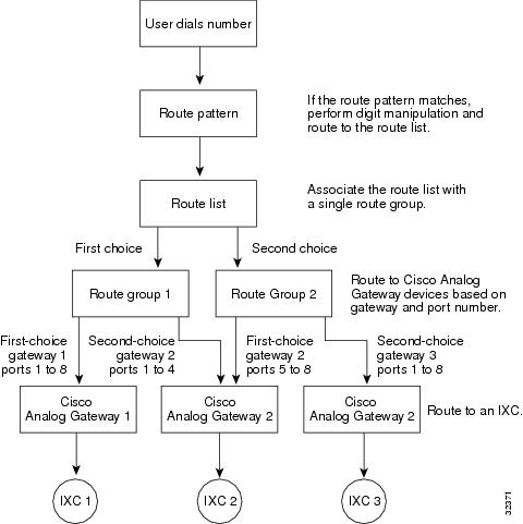
Figure 15-3 shows the effects of using route patterns with Cisco Analog Gateways. This example assigns the route pattern to a route list, and that route list associates with two route groups. Route group 1 associates with ports 1 through 8 on gateway 1, which routes all calls to interexchange carrier 1 (IXC 1). Route group 1 also associates with ports 1 through 4 on gateway 2. Route group 2 associates with ports 5 through 8 on gateway 2 and all ports on gateway 3.
Each route group supports a list of devices that are chosen on the basis of availability. For route group 1, if ports 1 through 8 on the first-choice gateway are busy or out of service, calls route to ports 1 through 4 on the second-choice gateway. If all routes in route group 1 are unavailable, calls route to route group 2. For route group 2, if ports 5 through 8 on the first-choice gateway are busy or out of service, calls route to ports 1 through 8 on the second-choice gateway. If no ports on any gateway in either route group are available, the call routes to an all trunks busy tone.
Figure 15-3 Route Plan Summary Diagram for Cisco Analog Access Gateways
Line Groups
Line groups contain one or more directory numbers. A distribution algorithm, such as Top Down, Circular, Longest Idle Time, or Broadcast, associates with a line group. Line groups also have an associated Ring No Answer reversion timeout value.
The following descriptions apply to the members of a line group:
•
•
•
For information on configuring line groups, refer to the "Line Group Configuration" section in the Cisco CallManager Administration Guide.
Note
Beginning with Release 4.1 of Cisco CallManager, a directory number may belong to more than one line group.
Hunt Lists
Hunt lists comprise ordered groupings of line groups. A line group may belong to more than one hunt list. Hunt pilots associate with hunt lists. A hunt list may associate with more than one hunt pilot.
For information on configuring hunt lists, refer to the "Hunt List Configuration" section in the Cisco CallManager Administration Guide.
Note
Note
Note
Hunt Pilots
Hunt pilots comprise sets of digits. They comprise lists of route patterns that are used for hunting. A hunt pilot can specify a partition, numbering plan, route filter, and hunt forward settings. A hunt pilot must specify a hunt list.
For information on configuring hunt pilots, refer to the "Hunt Pilot Configuration" section in the Cisco CallManager Administration Guide.
Note
Note
Note
Call Coverage
The Call Coverage feature, implemented in Release 4.1 of Cisco CallManager, comprises the following capabilities that are new to Cisco CallManager:
•
•
•
Hunting and Call Forwarding
The concept of hunting differs from that of call forwarding. Hunting allows Cisco CallManager to extend a call to one or more lists of numbers, where each such list can specify a hunting order that is chosen from a fixed set of algorithms. When a call extends to a hunt party from these lists and the party fails to answer or is busy, hunting resumes with the next hunt party. (The next hunt party varies depending on the current hunt algorithm.) Hunting thus ignores the Call Forward No Answer (CFNA) or Call Forward Busy (CFB) settings for the attempted party.
Call forwarding allows detailed control as to how to extend (divert and redirect represent equivalent terms for extend) a call when a called party fails to answer or is busy and hunting is not taking place. For example, if the CFNA setting for a line is set to a hunt-pilot number, a call to that line that is not answered diverts to the hunt-pilot number and thus begins hunting.
Starting with Release 4.1 of Cisco CallManager, Cisco CallManager offers the ability to redirect a call when hunting fails (that is, when hunting terminates without any hunt party answering, due either to exhausting the list of hunt numbers or to timing out). If used, this final redirection comprises a Call Forwarding action. Therefore, the Hunt Pilot Configuration window includes Call Forwarding configuration concepts that are similar to those found on the Directory Number Configuration window.
Example of Call Hunting
Although hunting differs from forwarding, hunting often originates as a call that gets forwarded to a hunt-pilot number. The call coverage feature extends hunting to allow final forwarding after hunting either exhausts or times out.
A typical call that invokes hunting can include the following phases:
1.
2.
3.
For the purpose of this example, we assume that hunting does not succeed.4.
Maximum Hunt Timer
The Maximum Hunt Timer field on the Hunt Pilot Configuration window allows the administrator to enter a value (in seconds) to limit the time for hunting through a hunt list. After the specified time elapses, if hunting has not succeeded, the call gets forwarded to a voice-messaging system, a specific dialed number, or some personal treatment (if configured), or the call gets released.
Show Line Group Member DN in finalCalledPartyNumber CDR Field Service Parameter
This service parameter for the Cisco CallManager service allows you to specify either the line group directory number (DN) that picks up a call to a hunt pilot number or the hunt pilot number as the final called party number in the Call Detail Record (CDR).
Refer to the Cisco CallManager 4.2(1) Call Detail Record Definition document for the details of setting this service parameter.
Internal and External Calls
Beginning with Release 4.1 of Cisco CallManager, forwarding provides separate configuration based on whether the originator of a call is an internal user or an external user. This distinction applies to both Call Forward Busy (CFB) and Call Forward No Answer (CFNA) cases.
Personal Preferences
Beginning with Release 4.1 of Cisco CallManager, hunting supports the capability to provide a final forwarding treatment to voice-messaging system, a specific dialed number, or some personal treatment (based on the original called party) when hunting either exhausts or times out. The capability to provide separate final forwarding treatment based on whether the call was internal or external also exists. Hunting supports a separate, configurable maximum hunt timer for each hunt-pilot number.
In the Hunt Pilot configuration settings, a check box named Use Personal Preferences exists to enable the Call Forward No Coverage (CFNC) settings for the original called number that forwarded the call to the hunt pilot. Refer to the "Hunt Pilot Configuration Settings" section in the Cisco CallManager Administration Guide.
Log Out of Hunt Groups
The Log Out of Hunt Groups feature allows the phone users to log out their phones from receiving calls that get routed to directory numbers that belong to line groups to which the phone lines are associated.
Regardless of the phone status, the phone rings normally for incoming calls that are not calls to the line group(s) that are associated with the phone.
The phone provides a visual status of the login state, so the user can determine by looking at the phone whether they are logged in to their line group(s).
Log Out of Hunt Groups Softkey
Cisco CallManager provides the HLog softkey that allows a phone user to log a phone out of all line groups to which the phone directory numbers belong. The user uses the HLog softkey to toggle between logon and logoff. After the feature is enabled (logoff) on a phone, calls that come into line groups that are associated with this phone skip this phone and go directly to the next line in the hunt list.
Because the Log Out of Hunt Groups feature is device-based, when the user enables the feature by pressing the HLog softkey, the phone gets logged off from all associated line groups. If a phone has directory numbers that belong to multiple line groups, pressing the HLog softkey logs the phone out of all associated line groups. The default phone state specifies logon.
The HLog softkey does not get added to any standard softkey template, but the HLog softkey displays as a selectable softkey in the Connected, Off Hook, and On Hook states in the Cisco CallManager Administration Softkey Layout Configuration window for a new softkey template. The HLog softkey displays on the phone when the phone is in the Connected, Off Hook, and On Hook states if the administrator adds the HLog softkey to the softkey template that the phone uses. If necessary, the softkey label gets translated to a different language.
A prompt status message displays the status of the feature when the softkey is pressed to log off, if the new softkey is selected in the Softkey Template that the device is currently using. If necessary, the prompt status message gets translated to a different language.
See the "Softkey Template Configuration" chapter in the Cisco CallManager Administration Guide for the details of configuring softkey templates in Cisco CallManager Administration.
Hunt Group Logoff Notification Service Parameter
The Hunt Group Logoff Notification service parameter in the Clusterwide Parameters (Device - Phone) section of the Service Parameters Configuration window for the Cisco CallManager service provides the option to turn audible ring tones on or off when calls that come in to a line group arrive at the phone and the current status of the phone is logoff. The default value specifies None, which causes the phone not to ring.
Non-Shared-Line Operation
If a phone is logged out of a line group and an extension on the phone is not shared, the line group does not ring that directory number in the line group. When the line group would normally offer the call to the directory number, call processing skips the directory number and acts as if the directory number does not belong to the line group.
Shared-Line Operation
Because the Log Out of Hunt Group feature is device-based, when a user logs a phone out, the feature affects only the logged-out phone. Calls to a line group that contains a shared-line directory number (DN) behave as follows:
•
•
•
Closest Match Routing
Closest match routing process routes a call by using the route pattern that most closely matches the dialed number. When the Cisco CallManager encounters a dialed number that matches multiple route patterns, it uses closest match routing to determine which route pattern most closely matches the number and directs the call by using that route pattern.
When two configured route patterns exactly match the same number of addresses in different partitions, Cisco CallManager chooses the route pattern on the basis of the order in which the partitions are listed in the calling search space. (Cisco CallManager chooses the route pattern from the partition that appears first in the calling search space.)
If two configured route patterns exactly match the same number of addresses in a partition, the Cisco CallManager arbitrarily chooses one. The following paragraphs explain why such exact matches signify an unusual occurrence.
Several route patterns can match a single number. For instance, the number 8912 matches all the following route patterns: 8912, 89XX, and 8XXX.
In this example, the route pattern 8912 matches exactly one address. The route pattern 89XX matches 8912 plus 99 other addresses, and the route pattern 8XXX matches 8912 plus 999 other addresses.
If the user dials 8913, the call routes differently. Using the preceding example, this address matches only the routing patterns 89XX and 8XXX. Because 89XX matches a narrower range of addresses than 8XXX, the Cisco CallManager delivers the call to the device that is assigned the routing pattern 89XX.
Using the @ Wildcard Character in Route Patterns
Using the @ wildcard character in a route pattern provides a single route pattern to match all NANP numbers, and requires additional consideration.
The number 92578912 matches both of the following route patterns: 9.@ and 9.XXXXXXX. Even though both these route patterns seem to equally match the address, the 9.@ route pattern actually provides the closest match. The @ wildcard character encompasses many different route patterns, and one of those route patterns is [2-9][02-9]XXXXX. Because the number 2578912 more closely matches [2-9][02-9]XXXXX than it does XXXXXXX, the 9.@ route pattern provides the closest match for routing.
When configuring route patterns, take the following considerations into account:
•
•
The "Special Characters and Settings" section lists DDIs and describes the effects of applying each DDI to a dialed number.
Discard Digits Instructions
A discard digits instruction (DDI) removes a portion of the dialed digit string before passing the number on to the adjacent system. Portions of the digit string must be removed, for example, when an external access code is needed to route the call to the PSTN, but the PSTN switch does not expect that access code.
Note
Static Digit Analysis
Prior to Release 4.0 of Cisco CallManager, unregistered devices without configured forwarding got removed from the digit analysis (DA) table and required dynamic digit analysis. Prior to Release 4.0, when a phone unregistered, call processing allowed a call to pass to the next closest match in the Calling Search Space (CSS) list. With the introduction of static DA in Release 4.0, whether a phone is registered or not, the device remains in the DA table, and the directory number intercepts the call.
Configuration Tip
•
Beginning with Release 4.0 of Cisco CallManager, the digit analysis process builds a static digit analysis engine with the patterns that are configured in the database during system initialization. This digit analysis engine reduces the propagation of patterns within a cluster of Cisco CallManagers and makes Cisco CallManager more scalable.
In previous releases, the individual device control process read pattern information from the database and dynamically registered the patterns to the digit analysis process to build its digit analysis engine. Each pattern had a mapping to its control process ID in the digit analysis engine. The control process ID of a pattern got changed dynamically if its associated device was reset or if a Cisco CallManager server restarted. If a change to the control process ID took place, the digit analysis engine had to be changed dynamically, and its contents required propagation to other Cisco CallManager servers. During call processing, the digit analysis engine returned the control process ID of a matched pattern.
Beginning with Release 4.0 of Cisco CallManager, the digit analysis process reads the pattern information directly from the database to build the static digit analysis engine during Cisco CallManager initialization. With the static digit analysis engine, each pattern has a mapping to its callable endpoint name, which is a NumPlanPkID of the pattern in the database, a unique identifier to a configured pattern in Cisco CallManager. The static digit analysis engine no longer holds the control process ID of a pattern.
Static digit analysis integrates with the changes to the device manager to support all existing functions and features. The device manager includes a table where a NumPlanPkID shows a one-to-one mapping to the control process ID of a pattern. When processing a call, digit analysis asks the device manager to get the control process ID for a matched pattern.
Feature Description
Cisco CallManager includes these pattern types: Call Park, Call Forward, Meet-Me Conference, Device, Translation, Call Pickup Group, Route, and Message Waiting. The Device, Translation, and Route pattern types represent static patterns. The digit analysis process reads these patterns directly and inserts them into the static digit analysis engine during the initialization of a Cisco CallManager. Other pattern types (Call Park, Call Forward, Meet-Me Conference, Call Pickup Group, and Message Waiting), which are intercept patterns, remain dynamic patterns. Their individual control process reads the pattern information from the database and then asks the digit analysis process to insert the pattern into the static digit analysis engine via registration messages.
All static patterns remain unchanged until their records are changed in the database. Static patterns do not require propagation because the database change notification is broadcast to the servers within a cluster. Dynamic patterns still use the existing propagating and updating mechanism to update the static digit analysis engines.
Regardless of its pattern type, each static pattern in the static digit analysis engine has a mapping to its PkID in the NumPlan table in the database. When a device registers its patterns to the device manager, the same PkID gets saved and mapped to its control process ID in the device manager. A new interface between the digit analysis and device manager retrieves the control process ID when a matched pattern is found in the static digit analysis engine during call processing.
Caveat 1
A potential loss of change notification exists in the current Cisco CallManager release. This loss could cause a device that is registered with Cisco CallManager to become unreachable by other devices. The following paragraphs provide troubleshooting for this potential problem.
The most common cause for this problem occurs when the DN that is assigned to the device belongs to a partition that is not contained in the calling search space of other devices. If the calling search space of other devices does contain the partition for that DN, other reasons may apply. For example, the DN changed only for that device, and the change notification from the database to Cisco CallManager was lost. Beginning with Release 4.0 of Cisco CallManager, resetting the device may not resolve the problem.
To resolve this problem, remove the DN and add the DN to the system again. Remove the DN from its device on the Directory Number Configuration window and on the Route Plan Report window. After you remove the DN, add it back in with the same partition, pattern, and other configuration information. The process should resolve the problem after you add the new DN to Cisco CallManager again.
The same workaround applies to route patterns and translation patterns if similar problems exist.
Tip
Caveat 2
Static digit analysis disables the configuration of several applications. These applications rely on the provision of duplicate patterns in the same calling search space. For example, the CTI application may be pattern 5000 in partition A, and a particular phone may be pattern 5000 in partition B. In previous releases, if the CTI route point is down, the phone will ring. With static digit analysis, however, the caller receives a busy tone. This limitation implies that the application failure does not get handled.
Administrators would normally use Call Forward No Answer and Call Forward on failure to handle application failure, but when the pattern on the CTI route point is 5XXX, you cannot configure a forward destination of 5XXX. To resolve this limitation, you can now perform configuration of X characters in Call Forward destinations.
The following example demonstrates the functionality of digit analysis prior to Release 4.0 (with dynamic digit analysis) and in Release 4.0 and subsequent releases (with static digit analysis) for the IPMA application.
IPMA Example with Digit Analysis Prior to Release 4.0
Given the following configuration
Partitions: IPMA, Managers, EveryoneCSS-I-E: IPMA:EveryoneCSS-M-E: Managers:EveryoneLine-1/CSS-I-E: EveryOne/1000Line-2/CSS-M-E: Manager/1001CTI RP: IPMA/1XXXTranslation Pattern/CSS-M-E: EveryOne/1XXXIf the CTI route point (RP) is up, 1000/IPMA:EveryOne calls 1001. The call routes by using the CTI route point IPMA/1XXX.
If the CTI route point is down, 1000/IPMA:EveryOne calls 1001. The call goes through the translation pattern Everyone/1xxx, and the call reaches Manager/1001 after the translation and achieves the goal of the IPMA application.
IPMA Example with Static Digit Analysis in Release 4.0 and Subsequent Releases
Given an identical configuration, in Release 4.0 and in subsequent releases, you must make the following modification: configure 1xxx as a CFNA mask and CSS-E as a CFNA calling search space for the CTI route point to handle the CTI route point failure case.
When static digit analysis gets used, the following processing takes place:
•
•
Without configuring the CFNA in the CTI route point, the translation pattern never gets matched, and the IPMA application fails.
Special Characters and Settings
Cisco CallManager Administration allows you to use special characters and settings to perform the following tasks:
•
•
•
•
For more information on how to use special characters and settings, see the following topics:
•
Wildcards and Special Characters in Route Patterns and Hunt Pilots
Wildcards and special characters in route patterns and hunt pilots allow a single route pattern or hunt pilot to match a range of numbers (addresses). Use these wildcards and special characters also to build instructions that enable the Cisco CallManager to manipulate a number before sending it to an adjacent system.
Table 15-3 describes the wildcards and special characters that Cisco CallManager supports.
Table 15-4 lists Cisco CallManager Administration fields that require route patterns or hunt pilots and shows the valid entries for each field.
Discard Digits Instructions
A discard digits instruction (DDI) removes a portion of the dialed digit string before passing the number on to the adjacent system. A DDI must remove portions of the digit string, for example, when an external access code is needed to route the call to the PSTN, but the PSTN switch does not expect that access code.
Table 15-5 lists DDIs and describes the effects of applying each DDI to a dialed number.
Calling and Called Party Transformations
Cisco CallManager Administration allows you to manipulate the calling party number and the called party number that Cisco CallManager sends with each call setup message.
The following topics provide information on these settings:
•
•
Calling Party Number Transformations Settings
Calling party transformations settings allow you to manipulate the appearance of the calling party number for outgoing calls. Cisco CallManager uses the calling party number for calling line identification (CLID). During an outgoing call, the CLID passes to each private branch exchange (PBX), central office (CO), and interexchange carrier (IXC) as the call progresses. The called party receives the calling line identification (CLID) when the call is offered to the called party.
Configuration for calling party transformations settings that are used in route lists occurs in the individual route groups that comprise the list. The calling party transformations settings that are assigned to the route groups in a route list override any calling party transformations settings that are assigned to a route pattern that is associated with that route list.
You can set the following calling party transformation settings in the route group configuration:
•
•
•
Table 15-6 describes the fields, options, and values that are used to specify calling party number transformations.
Called Party Number Transformations Settings
Called party transformations settings allow you to manipulate the dialed digits, or called party number, for outgoing calls. Examples of manipulating called numbers include appending or removing prefix digits (outgoing calls), appending area codes to calls dialed as seven-digit numbers, appending area codes and office codes to interoffice calls dialed as four- or five-digit extensions, and suppressing carrier access codes for equal access calls.
Configuration of called party transformations settings that are used in route lists occurs in the individual route groups that comprise the list. The called party transformations settings that are assigned to the route groups in a route list override any called party transformations settings that are assigned to a route pattern or translation pattern that is associated with that route list.
You can set the following called party transformation settings in the route group, route pattern, and translation pattern configuration:
•
•
•
Table 15-7 describes the fields, options, and values that are used to specify called party number transformations.
Table 15-7 Called Party Number Transformations Settings
Discard Digits
This field contains a list of discard patterns that control the discard digit instructions. For example, in a system where users must dial 9 to make a call to the public switched telephone network (PSTN), the PreDot discard pattern causes the 9 to be stripped from the dialed digit string. See the "Closest Match Routing" section for more information.
Note
Called Party Transform Mask
This field specifies the called party transform mask for all calls that are routed through this route group. Valid values for this field range from 0 through 9, the wildcard character X, and characters * and #. You can also leave this field blank. If this field is blank, no transformation takes place; Cisco CallManager sends the dialed digits exactly as dialed.
The called party transform mask can contain up to 50 digits.
Prefix Digits (Outgoing Calls)
This field contains a prefix digit or a set of Prefix Digits (Outgoing Calls) that are appended to the called party number on all calls that are routed through this route group. Valid values for this field range from 0 through 9, the characters * and #, and blank. Prefix Digits (Outgoing Calls) can contain up to 50 digits on route patterns or up to 24 digits on DNs.
Related Topics
•
•
Caller Identification and Restriction
Cisco CallManager provides the following types of caller identification information:
•
•
•
•
Cisco CallManger provides flexible configuration options to allow and to restrict the display of the line and name information for both calling and connected parties.
For more information on how to use caller identification settings, see the following topics:
•
•
Calling Party Presentation and Restriction Settings
Calling party presentation information controls whether to display the phone number and name information that Cisco CallManager sends with setup messages for an outgoing call. Cisco CallManager uses the following fields to provide these supplementary services:
•
•
You can use the Calling Line ID Presentation field in the Gateway Configuration window to control whether the CLID displays for all outgoing calls on the gateway. To control the CLID display on a call-by-call basis, you use the Calling line ID Presentation field in Route Pattern Configuration or Translation Pattern Configuration windows.
Note
The following example describes how calling line ID presentation works. When a user makes a call, Cisco CallManager checks whether the dialed number matches a translation pattern. Cisco CallManager finds a match and sets the presentation indicator to the value in the translation pattern Calling Line ID Presentation field, which specifies "restricted" in this example. Next, Cisco CallManager checks and finds a match on a route pattern that is configured for the dialed number. Cisco CallManager checks the Calling Line ID Presentation field and finds that the value specifies "default." The presentation indicator remains as "restricted" because the previous setting is unchanged when default is set.
The gateway Calling Line ID Presentation field gets checked last. In this example, the value specifies "allowed" and overrides the previous calling line ID presentation indicator to allow the calling party number to display on the called party phone. Therefore, the calling line ID presentation field indicator changed from "restricted" at the time that the calling party initiated the call to "allowed" by the time that Cisco CallManager sends the call setup message to the endpoint device.
You can configure line and name presentation or restriction on a call-by-call basis for outgoing calls and incoming calls by using the Route Pattern Configuration or Translation Pattern Configuration pages.
For the gateway, you can only configure calling line ID presentation for outgoing calls. For incoming calls, Cisco CallManager uses the Connected Line ID Presentation field for the gateway to specify whether to allow or restrict the connected party number to display on the calling party phone. Gateway settings only apply in these two situations, and these settings override all other settings. For the gateway, you can only configure calling and connected line presentation. No settings exist to control name presentation on the gateway.
The type of device control protocol that handles the call limits caller name and number information. See Table 15-10 for a list of protocols with the supported caller name and number information.
Note
Table 15-8 describes the fields, options, and values that are used to specify calling party presentations.
Table 15-8 Calling Party Presentation Settings
Calling Line ID Presentation (outgoing call)
This field determines whether the calling party phone number displays on the called party phone display screen. The Gateway Configuration, the Route Pattern Configuration, and the Translation Pattern Configuration windows use the Calling Line Presentation field.
The following list gives the options for this field:
•
•
•
Calling Name Presentation (outgoing call)
This field determines whether the calling party's name displays on the called party phone display. The Route Pattern Configuration and Translation Pattern Configuration windows use the Calling Name Presentation field.
The following list gives the options for this field:
•
•
•
Note
Calling Line ID Presentation (incoming call)
If the incoming call goes through a translation pattern or route pattern and the calling line ID presentation setting is allowed or restricted, the calling line presentation gets modified with the translation or route pattern setting. If the call comes into the Cisco CallManager system and then goes out to a PBX or the PSTN, the outgoing call rules apply as stated in the "Calling Party Presentation and Restriction Settings" section.
Note
Calling Name Presentation (incoming call)
If the incoming call goes through a translation pattern or route pattern and the calling name presentation setting is allowed or restricted, the calling name presentation gets modified with the translation or route pattern setting. If the call comes into the Cisco CallManager system and then goes out to a PBX or the PSTN, the outgoing call rules apply as stated in the "Calling Party Presentation and Restriction Settings" section.
Note
Connected Party Presentation and Restriction Settings
Connected party presentation information controls whether to display the phone number and name information that Cisco CallManager receives with an incoming call. Cisco CallManager uses the following fields to provide these supplementary services:
•
•
Connected party settings allow you to display or restrict the display of the phone number and name of the connected party on the calling party's phone. Translation Pattern Configuration and Route Pattern Configuration windows include these two settings. The calling party receives the connected name information after the call connects to Cisco CallManager and the terminating phone.
The following example describes how connected line ID works. When Cisco CallManager receives an incoming call, it checks whether a translation pattern is configured for the incoming number. Cisco CallManager uses the value in the Connected Line ID Presentation field that specifies "restricted" for this example. Next, if a route pattern is configured for the incoming call, the value in the Connected Line ID Presentation field gets checked. In this example, the value specifies "default," so the indicator remains as "restricted," which prevents the connected party number from displaying on the calling party's phone.
For incoming calls only, the gateway Connected Line ID Presentation field value gets checked last and is set for "allowed" in this example. The gateway setting specifies whether the connected party number can display on the calling party phone. In this case, Cisco CallManager sends "allowed" in the CONNECT message, so the connected line can display on the originating caller's phone display.
You can configure connected line and name presentation or restriction on a call-by-call basis for outgoing calls and incoming calls by using the Route Pattern Configuration or Translation Pattern Configuration windows.
For incoming calls on the gateway, you use the Connected Line ID Presentation field to specify whether to allow or restrict the display of the connected party number on the calling party's phone. Gateway settings only apply to line presentation settings and override all other settings.
Note
Table 15-9 describes the fields, options, and values that are used to specify connected party presentations.
Table 15-9 Connected Party Presentation Settings
Connected Line ID Presentation (outgoing call)
In the Route Pattern Configuration and the Translation Pattern Configuration windows, this field determines whether the connected party number displays on the calling party phone display.
The following list gives the options for this field:
•
•
•
Note
Connected Name Presentation (CONP/CONR) (outgoing call)
This field determines whether the connected party name displays on the calling party phone display. The Route Pattern Configuration and Translation Pattern Configuration windows use the Connected Name Presentation field.
The following list gives the options for this field:
•
•
•
Connected Line ID Presentation (incoming call)
If the incoming call goes through a translation or route pattern and the connected line ID presentation field is set to allowed or restricted, the connected line presentation indicator gets modified with the translation or route pattern setting.
Note
If the call comes into the Cisco CallManager system and then goes out to a PBX or the PSTN, the outgoing call rules apply as stated in the "Connected Party Presentation and Restriction Settings" section.
Connected Name Presentation (incoming call)
If the incoming call goes through a translation or route pattern and the connected name presentation setting is set to allowed or restricted, the connected name presentation gets modified with the translation or route pattern setting. If the call comes into the Cisco CallManager system and then goes out to a PBX or the PSTN, the outgoing call rules apply as stated in the "Connected Party Presentation and Restriction Settings" section.
Note
Caller Identification Support with Device Control Protocols in Cisco CallManager
Cisco CallManager provides support for caller name and number identification presentation based on the device control protocols that handle the call. Not all device protocols provide caller number and name information in the protocol messages. Table 15-10 summarizes which protocols support caller identification services.
Related Topics
•
•
•
External Route Plan Wizard
The external route plan wizard generates a single-tenant, multilocation, partitioned route plan for the North American Numbering Plan (NANP) area by using information that the administrator provides through a series of prompts.
The route plan that the external route plan wizard generates includes the following elements:
•
•
•
•
•
•
•
•
The following topics describe the basic concepts that are used when you generate route plans with the external route plan wizard:
Generated Route Filters
A generated route filter permits or restricts access through a route list by using route patterns. The external route plan wizard associates each route list with a particular route filter. It names route filters by using the TenantLocationCalltype convention and appends the suffix RF to each route filter for easy identification.
Table 15-11 shows the seven types of route lists that use route filters. The table shows examples that use specific route filter names and actual access and area codes for better readability.
Generated Route Groups
A generated route group sets the order of preference for gateway and port usage. The external route plan wizard assigns one gateway to each generated route group. The wizard uses all ports on the gateways. It does not support using partial resources for generated external route plans.
The external route plan wizard names route filters by using the TenantLocationGatewayTypeNumber convention for easy identification. The following list shows the gateway type abbreviations:
•
•
•
•
•
The external route plan wizard identifies route groups that are associated with multiple gateways of the same type by attaching a number suffix to all route groups. For example, if three MGCP trunk gateways exist at the Cisco Dallas location, the external route plan wizard names the associated route groups CiscoDallasMT1, CiscoDallasMT2, and CiscoDallasMT3.
If a route list includes more than one route group and more than one gateway (with one gateway for each route group), an arbitrary order designates how the external route plan wizard lists the route groups. The only order that is imposed ensures that route groups that are associated with the local gateways are listed before the route groups that are associated with remote gateways. If needed, manually change the order after the route plan is generated.
Note
Generated Route Lists
A generated route list sets the order of preference for route group usage and defines the route filters that are applied to those route groups. The external route plan wizard creates between five and seven route lists for each location depending on the types of local dialing choices that are available. Therefore, the total number of route lists depends on the local dialing scheme and the number of locations that the route plan serves.
Using the TenantLocationCalltype convention, the external route plan wizard names route lists and appends the suffix RL to each route list for easy identification.
Table 15-12 shows the various types of route lists. The examples shown in this table use specific route list names for better readability.
Generated Route Patterns
A generated route pattern directs calls to specific devices and either includes or excludes specific dialed-digit strings. The external route plan wizard only generates route patterns that require an access code prefix. The typical route pattern for routing a call to the PSTN includes the prefix construction 9.@. The typical route pattern for routing a call to the PBX includes the prefix construction 9.9@.
The external route plan wizard associates a route list, a route filter, and a partition with each route pattern. The route pattern provides the appropriate calling party transform mask, called party transform mask, digit discard instructions, and prefix digits for the associated route list.
The wizard bases route patterns for calls to an adjacent PBX on the access code and the range of directory numbers that are served by that PBX. For example, if the access code that is used to direct calls to the adjacent PBX is 9 and the range of directory numbers that is served by that PBX is 1000 through 1999, the external route plan wizard generates the route pattern 9.1XXX for enterprise calls.
Route Plan Report
The route plan report comprises a listing of all unassigned directory numbers (DN), call park numbers, call pickup numbers, conference numbers (Meet-Me numbers), directory numbers, route patterns, translation patterns, voice-mail ports, message-waiting indicators, and attendant console numbers in the system.
The route plan report allows you to view either a partial or full list and to go directly to the associated configuration windows by choosing a route pattern, partition, route group, route list, directory number, call park number, call pickup number, conference number (Meet-Me number), or gateway.
Using the route plan report, you can get a list of unassigned directory numbers and delete those numbers from the Cisco CallManager database, if required.
In addition, the route plan report allows you to save report data into a .csv file that you can import into other applications such as the Bulk Administration Tool (BAT). The .csv file contains more detailed information, including directory numbers (DN) for phones, route patterns, and translation patterns. Refer to the "Route Plan Report" section in the Cisco CallManager Administration Guide for more information.
Where to Find More Information
Related Topic
•
Related Cisco Documentation
•
•
•
•
•
•
•
•
•
•
•