-
Cisco CallManager Features and Services Guide, Release 4.0(1)
-
Index
-
Preface
-
Cisco CallManager Extension Mobility
-
Cisco IP Manager Assistant With Proxy Line Support
-
Cisco IP Manager Assistant With Shared Line Support
-
Cisco Call Back
-
Music On Hold
-
Cisco CallManager AutoAttendant
-
Barge and Privacy
-
Call Park
-
Immediate Divert
-
Malicious Call Identification
-
Multilevel Precedence and Preemption
-
Custom Phone Rings
-
Cisco WebDialer
-
Troubleshooting Features and Services
-
 Feedback
Table Of Contents
Multilevel Precedence and Preemption
User Access Channel Nonpreemptable
Common Network Facility Preemption
Unauthorized Precedence Announcement
Blocked Precedence Announcement
Busy Station Not Equipped for Preemption
MLPP Numbering Plan Access Control for Precedence Patterns
MLPP Hierarchical Configuration
Service Parameter Special Trace Configuration
CDR Recording for Precedence Calls
Installing and Activating MLPP
Setting the Enterprise Parameters for MLPP
Where to Find More Information
Multilevel Precedence and Preemption
The Multilevel Precedence and Preemption (MLPP) service allows properly validated users to place priority calls. If necessary, users can preempt lower-priority phone calls.
Precedence designates the priority level that is associated with a call. Preemption designates the process of terminating lower-precedence calls that are currently using the target device, so a call of higher precedence can be extended to or through the device.
An authenticated user can preempt calls either to targeted stations or through fully subscribed time division multiplexing (TDM) trunks. This capability assures high-ranking personnel of communication to critical organizations and personnel during network stress situations, such as a national emergency or degraded network situations.
This chapter covers the following topics:
•
Interactions and Restrictions
•
•
Introducing MLPP
The Multilevel Precedence and Preemption (MLPP) service allows placement of priority calls. Properly validated users can preempt lower-priority phone calls with higher-priority calls. An authenticated user can preempt calls either to targeted stations or through fully subscribed TDM trunks. This capability assures high-ranking personnel of communication to critical organizations and personnel during network stress situations, such as a national emergency or degraded network situations.
The following topics describe the MLPP service:
•
•
•
•
MLPP Terminology
The following terms apply to the MLPP service:
•
•
•
•
•
•
•
•
•
Precedence
Precedence indicates the priority level that is associated with a call. Precedence assignment is ad hoc in that the user may choose to apply or not to apply a precedence level to a call attempt. MLPP precedence does not relate to call admission control or enhanced emergency services (E911). Dedicated dial patterns in Cisco CallManager administration allow users to initiate an MLPP request. Configuration of the calling search space(s) (CSS) that is associated with the calling party (device, line, and so forth) controls a calling party's ability to dial a precedence pattern to attempt to originate a precedence call.
The Defense Switched Network (DSN) designates the target system for initial MLPP deployment. You generally can apply mechanisms for assigning precedence levels to calls, however, in Cisco CallManager Administration to any dial plan by defining precedence dial patterns and calling search spaces that allow or restrict access to these patterns. In the DSN, a dial plan gets defined such that a precedence call is requested by using the string prefix NP, where P specifies the requested precedence level and N specifies the preconfigured MLPP access digit. Table 11-1 lists the range of precedence values. Without specific invocation of precedence, the system processes a call by using normal call processing and call forwarding.
Table 11-1 Precedence Level
0 (highest)
Flash Override
1
Flash
2
Immediate
3
Priority
4 (lowest)
Routine
When a user profile is assigned to a phone, either as a default assignment or through extension mobility, the phone inherits the configuration of the assigned user, including any CSS that is associated with the user. The phone CSS can, however, override the user profile. Cisco CallManager assigns the precedence level that is associated with the dialed pattern to the call when a pattern match occurs. The system sets the call request as a precedence call with the assigned precedence level.
When a precedence call is offered to a destination, Cisco CallManager provides precedence indications to the source and destination of a precedence call, respectively, if either is MLPP Indication Enabled. For the source, this indication comprises a precedence ringback tone and display of the precedence level/domain of the call, if the device supports display. For the destination, the indication comprises a precedence ringer and display of the precedence level/domain of the call, if the device supports display.
Preemption
The preemption process terminates lower-precedence calls that are currently using the target device, so a call of higher precedence can be extended to or through the device. Preemption includes the notification and acknowledgement of preempted users and the reservation of shared resources immediately after preemption and prior to call termination. Preemption can take one of the following forms, depending on which method is invoked:
•
•
Note
Domain
The MLPP domain subscription of the originating user determines the domain of the call and its connections. Only higher-precedence calls in one domain can preempt connections that calls in the same domain are using.
Administrators enter domains in Cisco CallManager Administration as hexadecimal values of zero or greater.
MLPP Precedence Patterns
To set up MLPP precedence patterns, access the Translation Pattern Configuration window in Cisco CallManager Administration where he following MLPP precedence patterns are available:
•
•
•
•
•
•
Refer to the Translation Pattern Configuration section in the Cisco CallManager Administration Guide for details.
MLPP Indication Enabled
MLPP indication-enabled devices include the following characteristics:
•
•
•
To set up devices to enable MLPP indication, use the configuration window for each respective device. In the MLPP Indication field of each device, set the value to On.
Refer to the following topics for details of setting MLPP indication for devices:
•
•
•
•
•
Precedence Call Setup
The following sequence of events takes place during setup of a precedence call:
1.
2.
3.
Example
Party 1000 makes a precedence call to party 1001. To do so, party 1000 dials the precedence call pattern, such as 90-1001. In this example, 9 equals the precedence access digit, and 0 equals the precedence level (highest).
While the call processes, the calling party receives precedence ringback and precedence display on the calling Cisco IP Phone. After acknowledging the precedence call, the called party receives a precedence ringer (receives a special ring) and a precedence display on the called Cisco IP Phone.
Alternate Party Diversion
Alternate Party Diversion (APD) comprises a special type of call forwarding. If users are configured for APD, APD takes place when a precedence call is directed to a directory number (DN) that is busy or does not answer.
MLPP APD applies only to precedence calls. An MLPP APD call disables the DN Call Forward No Answer setting for precedence calls.
Precedence calls do not normally forward to voice messaging, as controlled by the value of the Use Standard VM Handling For Precedence Calls enterprise parameter. Refer to the "Setting the Enterprise Parameters for MLPP" section for details.
To set up APD, the administrator configures the Multilevel Precedence and Preemption Alternate Party Settings on the Directory Number Configuration window of the DN that is the target of an MLPP precedence call. Refer to the Cisco IP Phone Configuration section of the Cisco CallManager Administration Guide for details.
Example
Figure 11-1 illustrates the Alternate Party Diversion that takes place when a called party receives a precedence call and the party is configured for Alternate Party Diversion.
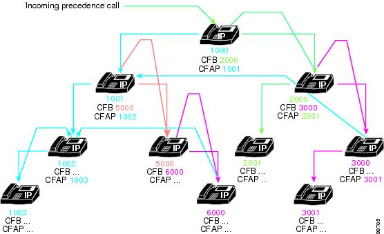
Figure 11-1 Alternate Party Diversion Example
In the example, a calling party placed a precedence call to party 1000. Called party 1000 has a Call Forward Busy (CFB) setting of 2000 and a Call Forward Alternate Party (CFAP) setting of 1001. The figure shows the CFB and CFAP settings for all other parties in this example.
When 1000 receives a precedence call but is busy, the call routes to party 2000. If party 2000 is also busy, the call routes to party 3000. If neither party 2000 nor party 3000 answers the call, however, the call routes to party 1001. That is, the call routes to the alternate party that is designated for the originally called party, not to the alternate parties that are designated for the Call Forward Busy parties that are associated with the originally called party.
Likewise, if party 1001 is busy and does not answer the call, the call forwards to party 5000. If party 5000 is busy, the call forwards to party 6000. If neither party 5000 nor party 6000 answers the call, however, the call forwards to party 1001's alternate party destination, which is party 1002. If party 1002 is busy or does not answer, the call forwards to party 1003, which is party 1002's alternate party designation.
MLPP Preemption Enabled
Enable MLPP preemption by explicitly configuring preemption-capable devices for preemption.
Receiving Preemption
A device that is preemption disabled (by setting the MLPP Preemption value to Disabled) can still receive precedence calls in an MLPP network, but the device itself does not get preempted. The preemption-disabled device can be connected to a call that gets preempted (at another device), in which case, the device receives preemption.
Preemption Enabled
Enable devices for preemption by setting the device MLPP Preemption value to either Forceful or Default. If the device MLPP Preemption value is set to Forceful, the system can preempt the device at its own interface. That is, the device can get preempted when a precedence call contends for the device resources.
If the device MLPP Preemption setting is Default, the device inherits its MLPP Preemption setting from its device pool. If the device's device pool MLPP Preemption setting is Forceful, or if the device pool MLPP Preemption setting is also Default but the MLPP Preemption Setting enterprise parameter value is Forceful Preemption, the device inherits preemption enabling.
To set up devices to enable MLPP preemption, use the configuration window for each respective device. In the MLPP Preemption field of each device, set the value to Forceful or Default.
Refer to the following topics for details of setting MLPP preemption for devices:
•
•
•
•
•
Preemption Details
Two types of preemption exist, User Access Preemption and Common Network Facility Preemption.
User Access Preemption
User access preemption takes place when a user places a precedence call to a user that is already active on a lower-level precedence call, assuming that both calls are in the same MLPP domain. You can use this type of preemption for MLPP Indication Enabled phones that the Cisco Skinny Client Control Protocol controls in the Cisco CallManager MLPP system. Preemption occurs if a precedence call request is validated and if the requested precedence of the call is greater than the precedence of an existing call that is connected at the destination MLPP Preemption Enabled phone. Call processing uses a preemption tone to notify the connected parties of the preemption and releases the active call. When the called party acknowledges the preemption by hanging up, the called party gets offered the new MLPP call.
To understand the sequence of steps that takes place during user access preemption, see the following example.
Example
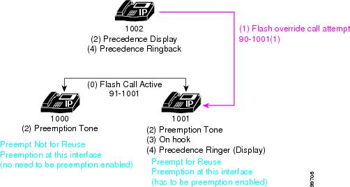
Figure 11-2 illustrates an example of user access preemption.
Figure 11-2 User Access Preemption Example
In the example of user access preemption, the following sequence of events takes place:
1.
2.
3.
4.
5.
Distinct preemption types take place in this instance. For the party that is not the destination of the higher-precedence call, Preemption Not for Reuse takes place. Because preemption is not taking place at this interface, this device does not need to be preemption enabled. For the party that is the destination of the higher-precedence call, Preemption for Reuse takes place. Because preemption does take place at this interface, ensure that this device is preemption enabled.
User Access Channel Nonpreemptable
You can configure an end-user device as MLPP Indication Enabled but not MLPP Preemption Enabled. In this case, a phone can generate MLPP indications (using special preemption tones and ringers) does not have preemption procedures supported in its device control protocol in Cisco CallManager. The administrator can also disable preemption procedures for a phone even though Cisco CallManager Administration supports the procedures.
Historically, user access devices (phones) have limited or no mechanisms for handling multiple simultaneous calls. Even with the Call Waiting feature, many phones and associated switches do not have a mechanism to allow the user to manage multiple calls simultaneously on the same line.
Cisco CallManager Administration effectively enhances the Call Waiting feature to provide this capability for users of Cisco IP Phones (794X and 796X series). These Cisco IP Phones include a user interface that gives the user adequate control of multiple, simultaneous calls when interfacing with the Cisco CallManager system. With this enhanced functionality, the Call Waiting feature can be applied to all precedence calls directed to these types of phones, even though the user may already be managing other calls. When the user receives a precedence call, the user at a destination phone can decide what to do with any existing calls instead of merely releasing the lower-precedence call. For users of these devices, the Cisco CallManager administrator can configure devices as not MLPP Preemption Enabled to take advantage of this function in Cisco CallManager.
Common Network Facility Preemption
Common network facility preemption applies to network resources, such as trunks, in the MLPP system. When a common network facility gets preempted, all existing parties receive notification of the preemption, and the existing connection immediately gets disconnected. The new call gets set up by using the preempted facility in the normal manner without any special notification to the new called party. PRI and T1-CAS trunks on targeted MGCP gateway platforms support this type of preemption in Cisco CallManager.
Preemption occurs if a precedence call request is validated and if the requested precedence of the call is greater than the precedence of an existing call through the destination MLPP Preemption Enabled trunk and the trunk is completely busy (that is, cannot handle any more calls). Call processing identifies a call with lower precedence, notifies the connected parties of the preemption for the PRI trunk interface, reserves the channel for subsequent use, and drops the selected lower-precedence call. The system uses the reserved channel to establish the connection through the gateway for the precedence call that caused preemption.
For the sequence of steps that takes place during common network facility preemption, see the following examples.
Example 1
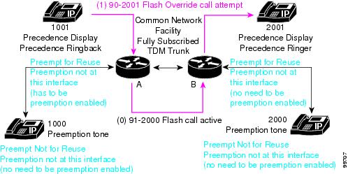
Figure 11-3 illustrates an example of common network facility preemption.
Figure 11-3 Common Network Facility Preemption Example
In the example of common network facility preemption, the following sequence of events takes place:
1.
The call uses a common network facility where the two gateways define a fully subscribed TDM trunk.
2.
Preemption occurs at gateway A, which is preempted for reuse. Because preemption occurs at this interface, you must ensure that this device is preemption enabled. Gateway B also gets preempted for reuse, but the preemption does not occur at this interface, so this device does not need to be preemption enabled.
Users 1000 and 2000 both receive preemption tones. Because both devices are not preempted for reuse and preemption does not occur at these interfaces, you do not need to ensure that these devices are preemption enabled for the preemption to occur.
In this example, almost all events occur instantly. Parties do not need to hang up for common network facility preemption to occur.
Example 2
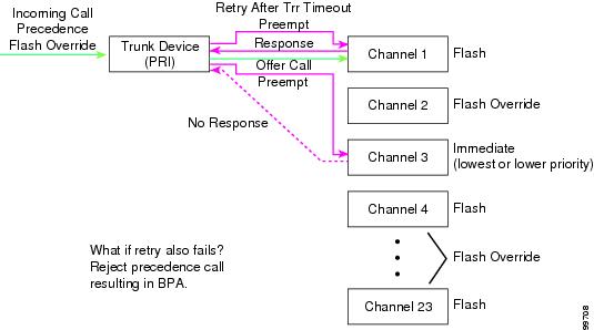
Figure 11-4 illustrates an example of common network facility preemption with the retry timer Trr. The retry timer Trr provides a mechanism, so if preemption is not successful on one channel, preemption gets retried on another channel. This timer applies only to TDM trunks.
Figure 11-4 Common Network Facility Preemption Example with Retry Timer Trr
In the example of common network facility preemption with the retry timer Trr, the following sequence of events takes place:
1.
The incoming call causes preemption of channel 3, but a response does not occur within the time that the retry timer Trr specifies.
2.
Channel 3 gets preempted.
3.
MLPP Announcements
Users who unsuccessfully attempt to place MLPP precedence calls receive various announcements that detail the reasons why a precedence call was blocked.
The following sections discuss specific MLPP announcements:
•
•
•
The Supported Tones and Announcements topic in the Annunciator section of the Cisco CallManager System Guide discusses MLPP announcements. Refer to the Route Pattern/Hunt Pilot Configuration and Translation Pattern Configuration sections in the Cisco CallManager Administration Guide for details of configuring the Precedence Level Exceeded condition that generates the Unauthorized Precedence Announcement.
Related Topics
•
•
•
•
Unauthorized Precedence Announcement
Users receive an unauthorized precedence announcement when they attempt to make a call with a higher level of precedence than the highest precedence level that is authorized for their line. A user receives an unauthorized precedence announcement when the user dials a precedence call by using a calling pattern for which the user does not have authorization.
Cisco CallManager recognizes the Precedence Level Exceeded condition only if specific patterns or partitions are configured to block a call attempt that matches the pattern and that indicates the reason that the call is blocked.
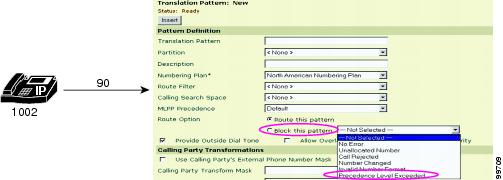
To assign authorized calling patterns, access the Route Pattern/Hunt Pilot Configuration and the Translation Pattern Configuration windows in Cisco CallManager Administration. To configure the MLPP Precedence Level Exceeded condition, use the Route Option field of the Route Pattern/Hunt Pilot Configuration and Translation Pattern Configuration windows and choose the Block this pattern option in Cisco CallManager Administration. In the drop-down list box, choose Precedence Level Exceeded. Refer to the Route Pattern/Hunt Pilot Configuration and Translation Pattern Configuration sections of the Cisco CallManager Administration Guide for details.
Example
Figure 11-5 illustrates an example of a user that receives an unauthorized precedence announcement.
Figure 11-5 Unauthorized Precedence Announcement Example
In the example, user 1002 dials 90 to start a precedence call. Nine (9) represents the precedence access digit, and zero (0) specifies the precedence level that the user attempts to use. Because this user is not authorized to make flash override precedence calls (calls of precedence level 0), the user receives an unauthorized precedence announcement.
Blocked Precedence Announcement
Users receive a blocked precedence announcement if the destination party for the precedence call is off hook, or if the destination party is busy with a precedence call of an equal or higher precedence and the destination party does not have the Call Waiting nor Call Forward features nor a designated party for alternate party diversion (APD), or due to a lack of a common network resource.
Example
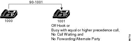
Figure 11-6 provides an example of a blocked precedence announcement.
Figure 11-6 Blocked Precedence Announcement Example
In this example, user 1000 makes a precedence call to user 1001 by dialing 90-1001. Because user 1001 is either off hook or busy with a precedence call of equal- or higher-precedence level and user 1001 does not have Call Waiting nor Call Forward nor an alternate party that is designed for alternate party diversion, user 1000 receives a blocked precedence announcement.
Busy Station Not Equipped for Preemption
Users receive this announcement if the dialed number is nonpreemptable. That is, the dialed number registers as busy and has no call waiting, no call forwarding, and no alternate party designations.
MLPP Numbering Plan Access Control for Precedence Patterns
MLPP uses the calling search spaces and partitions that are defined for users to authenticate and validate MLPP calls and provide access control for precedence patterns.
The maximum precedence of a user gets set at user configuration time. All MLPP-capable station devices gets configured as either MLPP-enabled or MLPP-disabled. A device to which a user profile is applied inherits the precedence level of that user with respect to precedence calls that are initiated from that device. A device that has a default user assigned inherits a Routine precedence level for the default user.
Configuration of the calling search space(s) (CSS) that is associated with the calling party controls a user's ability to dial a precedence pattern (that is, to initiate a precedence call). Cisco CallManager does not provide for explicit configuration of an explicit maximum allowed precedence value.
The following example illustrates the differences in access to precedence calls for two users who try to place a priority-level precedence call to a third user.
Example
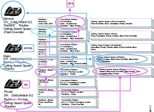
Figure 11-7 provides an example of MLPP numbering plan access control for precedence patterns.
Figure 11-7 MLPP Numbering Plan Access Control for Precedence Patterns Example
The table defines three users in this illustration:
General
1000
Routine
Flash Override
Major
2000
Routine
Priority
Private
3000
Routine
Routine
The example shows the use of partitions and calling search spaces to limit access to precedence calls.
If private 3000 tries to place a precedence call by dialing the precedence pattern 93, the following events take place:
•
•
•
•
If major 2000 places a precedence call by dialing the digits 931000, the following events take place:
•
•
•
•
MLPP Trunk Selection
MLPP trunk selection entails hunting for available trunks by using route lists and route groups. In Cisco CallManager Administration, you can configure a route list and associated route group(s) to route calls to several gateways via a single dial pattern to find an available channel. Although a route list has many trunk resources to which the route list can route calls, the individual resources may be spread across many gateways.
When no available trunk resource is identified in a collection of gateways (that is, a route list and route group configuration), Cisco CallManager attempts to initiate preemption of a lower-level precedence shared resource in the collection. Two methods exist for subsequently searching for a preemptable channel within a route list and route group configuration.
Method 1
Configure a route list and a separate route group for each available route (trunk interface). Designate one route group as the Direct route group and designate the other route groups as Alternate route groups. Add the Direct Route trunk interface (gateway) as the only member of the Direct route group. Add the Alternate Route gateways to the individual Alternate route groups. Associate the route groups with the route list, configuring the Direct route group as the first route group in the route list, and choose the Top Down distribution algorithm for each route group association.
Using this configuration, the Direct gateway in the Direct route group gets searched for an idle channel first. If no idle channel is found in the Direct gateway, the system initiates preemptive trunk selection for this Direct gateway as follows:
•
•
Method 2
Configure a route list and a single route group. Add trunk interfaces (gateways) to the route group and position the Direct Route gateway as the first gateway in the route group. Associate the route group with the route list and choose the Top Down distribution algorithm. With this configuration, the system searches all gateways in the route group for an idle channel first. If no idle channel is found in any gateway in the route group, preemptive trunk selection begins with the first gateway in the route group (that is, the Direct Route gateway) as follows:
•
•
Example
The following example illustrates two methods for finding an available trunk device when an incoming flash-level precedence call seeks an available trunk device.
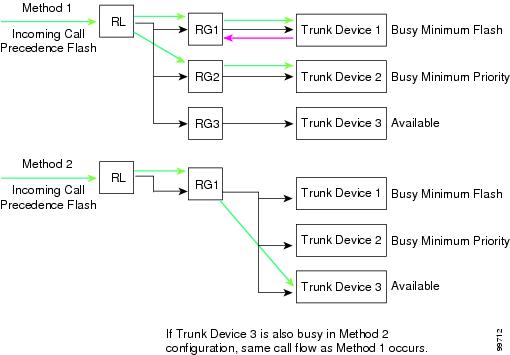
Figure 11-8 provides an example of MLPP trunk selection using route lists and route groups to hunt for an available trunk device.
Figure 11-8 MLPP Trunk Selection (Hunting) Example
In method 1, the following sequence of events takes place:
1.
For Trunk Device1, calls must be of a higher precedence than flash to preempt calls that are using this device.
2.
Because this call is a higher-precedence call, the call preempts the existing call on Trunk Device2.
In method 2, the following sequence of events takes place:
1.
2.
Of the three trunk devices in RG1, Trunk Device1 and Trunk Device2 registers as busy, so the system offers the call to Trunk Device3, which is available.
MLPP Hierarchical Configuration
MLPP settings for devices follow this hierarchy:
•
•
•
MLPP settings for device pools follow this hierarchy:
•
•
•
The MLPP Indication Status enterprise parameter defines the indication status of device pools and device pools in the enterprise, but non-default settings for device pools and individual devices can override its value. The default value for this enterprise parameter specifies MLPP Indication turned off.
The MLPP Preemption Setting enterprise parameter defines the preemption ability for device pools and devices in the enterprise, but nondefault settings for device pools and individual devices can override its value. The default value for this enterprise parameter specifies No preemption allowed.
The MLPP Domain Identifier enterprise parameter specifies the MLPP domain. The MLPP service applies only to a domain; that is, only to the subscribers and the network and access resources that belong to a particular domain. Connections and resources that belong to a call from an MLPP subscriber get marked with a precedence level and an MLPP domain identifier. Only calls of higher precedence from MLPP users in the same domain can preempt lower-precedence calls in the same domain.
Service Parameter Special Trace Configuration
MLPP issues a service parameter for tracing.
Refer to the Cisco CallManager Serviceability System Guide and the Cisco CallManager Serviceability Administration Guide for details.
CDR Recording for Precedence Calls
MLPP precedence calls generate call detail records (CDRs). The CDR identifies the precedence level of the precedence call.
The same precedence levels of the call legs generally apply. With transfer or conference calls, the precedence levels can differ; therefore, Cisco CallManager CDRs identify the precedence level of each leg of the call.
Cisco CallManager CDRs document the preemption value for preempted call terminations.
Refer to the Cisco CallManager Serviceability System Guide and the Cisco CallManager Serviceability Administration Guide for details.
Line Feature Interaction
MLPP interacts with line features as described in the following sections:
Call Forward
MLPP interacts with the call forward features as described in the following list:
•
–
–
–
–
–
–
•
–
–
If no Alternate Party setting is configured for the destination of a precedence call, call processing diverts the precedence call to the Call Forward No Answer setting.
–
Call Transfer
MLPP interacts with the call-transfer feature. For blind transfers and consult transfers, each connection of the transferred call, including the consult call, maintains the precedence that the connection was assigned when the call was established.
Shared Lines
MLPP interacts with shared lines. A shared line appearance with a call on hold may be preempted to establish a higher-precedence call to another terminal with the same directory number (DN). In this case, the original held call does not disconnect, and the precedence call connects. After the precedence call ends, the user may retrieve the original held call.
Call Waiting
MLPP interacts with the call-waiting feature as described in the following list:
•
•
–
–
–
–
Call Preservation
Any MGCP trunk call or connection that is preserved according to the Cisco CallManager Call Preservation feature preserves its precedence level and MLPP Domain after invoking the Call Preservation feature. After the device registers with Cisco CallManager, the system only preserves the preserved calls at the device layer in the Cisco CallManager system. As a result, the preserved calls gets treated as two disjoint half calls. If preemption does occur on these devices, only one leg would be able to follow preemption protocol to the other leg. The system detects call termination only through closure of the RTP port.
Automated Alternate Routing
The Automated Alternate Routing (AAR) for Insufficient Bandwidth feature, an extension of AAR, provides a mechanism to automatically fall back to reroute a call through the Public Switched Telephone Network (PSTN) or other network by using an alternate number when the Cisco CallManager blocks the call due to insufficient location bandwidth. With this feature, the caller does not need to hang up and redial the called party.
If a precedence call attempt meets a condition that invokes the AAR service, the precedence call gets rerouted through the PSTN or other network as specified by the AAR configuration. Cisco CallManager handles the precedence nature of the call in the same manner as if the call originally had been routed through the PSTN or other network, based on the MLPP Indication Enabled and MLPP Preemption Enabled nature of the network interface through which the call is routed.
For details of configuring Automated Alternate Routing, refer to the Automated Alternate Routing Group Configuration section of the Cisco CallManager Administration Guide.
MGCP and PRI Protocol
MLPP supports Common Network Facility Preemption only for T1-CAS and T1-PRI (North American) interfaces on targeted Voice over IP gateways that Cisco CallManager controls by using MGCP protocol and that have been configured as MLPP Preemption Enabled.
Interactions and Restrictions
The following sections describe the interactions and restrictions for MLPP.
Interactions
MLPP interacts with the following Cisco CallManager features as follows:
•
•
•
–
–
–
Restrictions
The following restrictions apply to MLPP:
•
•
•
•
–
–
•
•
For trunks, MLPP indication and preemption function independently.
•
Refer to the "Configuring MLPP" section for configuration details.
Installing and Activating MLPP
MLPP, a system feature, comes standard with Cisco CallManager software and does not require special installation.
Configuring MLPP
This section contains the following information:
•
MLPP Configuration Checklist
Table 11-2 provides a checklist to configure MLPP.
Table 11-2 MLPP Configuration Checklist
Step 1
Configure a device pool for which associated devices can make MLPP calls.
Device Pool Configuration, Cisco CallManager Administration Guide
Step 2
Set enterprise parameters to enable MLPP indication and preemption. If individual devices and devices in device pools have MLPP settings of Default, the MLLP-related enterprise parameters apply to these devices and device pools.
Setting the Enterprise Parameters for MLPP
Enterprise Parameters Configuration, Cisco CallManager Administration Guide
Step 3
Configure partitions and Calling Search Spaces (CSS) that allow users (calling parties and their associated devices) to place precedence calls that use MLPP.
Partition Configuration, Cisco CallManager Administration Guide
Calling Search Space Configuration, Cisco CallManager Administration Guide
Step 4
Configure route patterns/hunt pilots that specify MLPP precedence level and route options for MLPP calls.
Route Pattern/Hunt Pilot Configuration, Cisco CallManager Administration Guide
Step 5
Configure translation patterns that specify MLPP precedence level and route options for MLPP calls.
Translation Pattern Configuration, Cisco CallManager Administration Guide
Step 6
Configure gateways that specify an MLPP domain for MLPP calls. The following gateway types apply:
•
•
•
•
•
•
•
•
•
•
•
•
Note
Gateway Configuration, Cisco CallManager Administration Guide
Step 7
Configure Cisco IP Phones that specify an MLPP domain for MLPP calls.
Note
Cisco IP Phone Configuration, Cisco CallManager Administration Guide
Step 8
Configure the directory number that will place an MLPP call.
Cisco IP Phone Configuration, Cisco CallManager Administration Guide
Step 9
Configure the User Device Profile of the user that will make an MLPP call.
Device Profile Configuration, Cisco CallManager Administration Guide
Step 10
Configure the Device Profile Default for devices that will make MLPP calls.
Device Profile Default Configuration, Cisco CallManager Administration Guide
Step 11
Notify users that the MLPP service is available.
Refer to the phone documentation for instructions on how users access MLPP features on their Cisco IP Phone.
Setting the Enterprise Parameters for MLPP
Cisco CallManager provides the following enterprise parameters that apply to MLPP. Set the MLPP-related enterprise parameters as indicated to allow MLPP service.
•
Note
•
Note
•
Note
•
•
For more information about enterprise parameters, refer to the Enterprise Parameters Configuration chapter of the Cisco CallManager Administration Guide.
Where to Find More Information
Related Topics
•
•
•
•
•
•
•
•
•
•
•
•
•
Additional Cisco Documentation
•
•
•