Feedback Feedback
|
Table Of Contents
Task List to Create the Integration
Task List to Change the Number of Voice Messaging Ports
Integrations with Multiple Phone Systems
Planning How the Voice Messaging Ports Will Be Used by Cisco Unity Connection
Programming the Cisco Unified CM Express Phone System
Creating a New Integration with the Cisco Unified Communications Manager Express Phone System
(Multiple Integrations Only) Adding New User Templates
Changing the Number of Voice Messaging Ports
Appendix: Documentation and Technical AssistanceObtaining Documentation, Obtaining Support, and Security Guidelines
Cisco Unified Commuications Manager Express 4.1 SCCP Integration Guide for Cisco Unity Connection 1.2
Published March 21, 2007
This document provides instructions for integrating Cisco Unified Communications Manager (CM) Express (formerly known as Cisco Unified CallManager Express) with Cisco Unity Connection by Skinny Call Control Protocol (SCCP).
Cisco Unity Connection supports an SCCP integration when the Cisco Unified CM Express phone system has only SCCP phones or has both SCCP and SIP phones.
Note
The G.729a codec is not supported.
Integration Tasks
Before doing the following tasks to integrate Cisco Unity Connection with the Cisco Unified Communications Manager Express phone system, confirm that the Cisco Unity Connection server is ready for the integration by completing the applicable tasks in the Cisco Unity installation guide.
The following task lists describe the process for creating an integration and changing the number of voice messaging ports.
Task List to Create the Integration
Use the following task list to set up a new integration with the Cisco Unified Communications Manager Express phone system. If you are installing a new Cisco Unity Connection server by using the Cisco Unity installation guide, you may have already completed some of the following tasks.
1.
2.
3.
4.
Note
5.
6.
Task List to Change the Number of Voice Messaging Ports
Use the following task list to change the number of voice messaging ports for an integration after it has been created.
1.
Requirements
The Cisco Unified Communications Manager Express integration supports configurations of the following components:
Phone System
•
•
•
•
•
•
•
Cisco Unity Connection Server
•
•
•
•
Integration Description
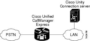
The Cisco Unified Communications Manager Express integration uses the LAN to connect Cisco Unity Connection and the phone system. The Cisco Unified Communications Manager Express also provides connections to the PSTN. Figure 1 shows the connections for a system with a single Cisco Unified Communications Manager Express router.
Figure 1 Connections Between the Phone System and Cisco Unity Connection
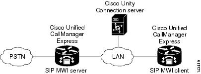
Figure 2 shows the connections for a system with multiple Cisco Unified Communications Manager Express routers and a single Cisco Unity Connection server. One Cisco Unified Communications Manager Express router acts as the SIP MWI server, and the remaining Cisco Unified Communications Manager Express routers act as SIP MWI clients. Note that Cisco Unity Connection voice messaging ports register with only the SIP MWI server (the Cisco Unified Communications Manager Express router that is on the same LAN as the Cisco Unity Connection server), not with the SIP MWI clients.
Figure 2 Connections Between Multiple Cisco Unified Communications Manager Express Routers and a Single Cisco Unity Connection Server
Call Information
The phone system sends the following information with forwarded calls:
•
•
•
Cisco Unity Connection uses this information to answer the call appropriately. For example, a call forwarded to Cisco Unity Connection is answered with the personal greeting of the user. If the phone system routes the call to Cisco Unity Connection without this information, Cisco Unity Connection answers with the opening greeting.
Integration Functionality
The Cisco Unified Communications Manager Express integration with Cisco Unity Connection provides the following features:
•
•
•
•
•
•
These integration features are not available to analog phones connected through FXS ports on the Cisco Unified Communications Manager Express phone system. Analog phones connected to ATA, however, support all integration features, except MWIs (MWI lamps will not light, though the stutter dial tone will sound).
Integrations with Multiple Phone Systems
Cisco Unity Connection can be integrated with multiple phone systems at one time. For information on and instructions for integrating Cisco Unity Connection with multiple phone systems, refer to the Multiple Phone System Integration Guide at http://www.cisco.com/en/US/products/ps6509/products_installation_and_configuration_guides_list.html.
Planning How the Voice Messaging Ports Will Be Used by Cisco Unity Connection
Before programming the phone system, you need to plan how the voice messaging ports will be used by Cisco Unity Connection. The following considerations will affect the programming for the phone system (for example, setting up the hunt group or call forwarding for the voice messaging ports):
•
•
•
The following table describes the voice messaging port settings in Cisco Unity Connection that can be set on Telephony Integrations > Port of Cisco Unity Administrator.
The Number of Voice Messaging Ports to Install
The number of voice messaging ports to install depends on numerous factors, including:
•
•
•
•
•
•
•
•
It is best to install only the number of voice messaging ports that are needed so that system resources are not allocated to unused ports.
The Number of Voice Messaging Ports That Will Answer Calls
The calls that the voice messaging ports answer can be incoming calls from unidentified callers or from users. Typically, the voice messaging ports that answer calls are the busiest.
You can set voice messaging ports to both answer calls and to dial out (for example, to send message notifications). However, when the voice messaging ports perform more than one function and are very active (for example, answering many calls), the other functions may be delayed until the voice messaging port is free (for example, message notifications cannot be sent until there are fewer calls to answer). For best performance, dedicate certain voice messaging ports for only answering incoming calls, and dedicate other ports for only dialing out. Separating these port functions eliminates the possibility of a collision, in which an incoming call arrives on a port at the same time that Cisco Unity Connection takes the port off-hook to dial out.
The Number of Voice Messaging Ports That Will Only Dial Out, and Not Answer Calls
Ports that will only dial out and will not answer calls can do one or more of the following:
•
•
•
Typically, these voice messaging ports are the least busy ports.
Caution
Preparing for Programming the Phone System
Record your decisions about the voice messaging ports to guide you in programming the phone system.
Programming the Cisco Unified CM Express Phone System
After the Cisco Unified Communications Manager Express router is installed, do the procedures in the applicable section depending on the number of Cisco Unified Communications Manager Express routers you will integrate with the Cisco Unity Connection server:
•
•
Programming a Single Cisco Unified Communications Manager Express Router to Integrate with a Single Cisco Unity Connection Server
Note
To Configure the Message Button Access to Cisco Unity Connection
This procedure configures the Message button on Cisco IP phones to dial the Cisco Unity Connection pilot number when pressed.
Step 1
telephony-service
Step 2
voicemail <Cisco Unity Connection pilot number>
Step 3
exit
The following is an example of the configuration:
telephony-servicevoicemail 4001To Configure the Router for Cisco Unity Connection
Step 1
ephone-dn <DN tag>
Step 2
number <voice messaging port extension>
Note
Step 3
name <user name of voice messaging port>
Step 4
no huntstop
Step 5
preference <preference order>
Step 6
Note
Step 7
exit
The following is an example of the configuration:
ephone-dn 32number 4001name "Voice Messaging Port 1"no huntstop!ephone-dn 33number 4001name "Voice Messaging Port 2"no huntstoppreference 1!ephone-dn 34number 4001name "Voice Messaging Port 3"no huntstoppreference 2!ephone-dn 35number A01name "MWI Only"In this example, there are four ephone-dns configured to provide four voice messaging ports. Three of the ephone-dns are configured with the same extension number to provide ports dedicated for leaving and retrieving voice messages. The fourth ephone-dn is provided for use as an MWI-only port. The first three ephone-dns are configured with the same extension number (4001), using preferences 0, 1, and 2 to create a hunt group. If the first port is busy, the call goes to the second port, and so on. Port 4 is configured with the extension number A01 and is used to set MWIs by Cisco Unity Connection. Separate ports are required for answering calls and setting MWIs in order to prevent call-collision problems between incoming calls placed by Cisco Unified Communications Manager Express to Cisco Unity Connection, and MWI calls that Cisco Unity Connection places in the opposite direction.
To Associate the Voice Messaging Port Device
To associate the actual voice messaging port device (vm-device-id) to the phone number, associate the Cisco IP phone with the voice messaging port device.
The vm-device-id name uses the following format:
<Cisco Unity Connection device name prefix><Port number>
The default vm-device-id name is CiscoUM-VI1. The vm-device-id name must match the Cisco Unity Connection voice messaging port name you will use to identify the port in Cisco Unity Administrator when you create the integration:
•
•
To associate a voice mail device to the Cisco Unified Communications Manager Express router, do the following steps, beginning in ephone configuration mode.
Step 1
ephone <DN tag>
Step 2
vm-device-id <Cisco Unity Connection device name prefix><port number>
For example, if the Cisco Unity Connection device name prefix is CiscoUM-VI, enter CiscoUM-VI1 for the first port and CiscoUM-VI2 for the second port, and so on.
Note
Step 3
button <button number>:<DN tag>
For example, you can use the values 1:1, 2:4, or 3:14. In this example, button 1 corresponds to directory number 1 (ephone-dn 1), button 2 corresponds to directory number 4, and button 3 corresponds to directory number 14. The buttons correspond to the phone lines on the Cisco IP phone.
Step 4
Note
Step 5
exit
Following is an example of the configuration. In this example, the vm-device-id command is used within the ephone configuration in place of the mac-address parameter that is used for configuring a regular Cisco IP phone.
ephone 5vm-device-id CiscoUM-VI1button 1:32!ephone 6vm-device-id CiscoUM-VI2button 1:33!ephone 7vm-device-id CiscoUM-VI3button 1:34!ephone 8vm-device-id CiscoUM-VI4button 1:35To Configure a Directory Number for MWI Notification
MWI configuration on the Cisco Unified Communications Manager Express is performed by dedicating Cisco IP phone directory numbers (ephone-DNs) to process MWI status notification calls originating from Cisco Unity Connection. You must allocate a minimum of one MWI processing ephone-dn for each MWI ephone-dn voice messaging port. The MWI processing ephone-dn extensions are configured to match the MWI extensions configured on Cisco Unity Connection.
Step 1
ephone-dn <DN tag>
Step 2
number <MWI on number> secondary <MWI off number>
Note
Step 3
mwi on-off
Step 4
exit
Following is an example of the configuration.
ephone-dn 32number 8000 secondary 8001mwi on-offIn this example, Cisco Unity Connection calls extensions 8000 and 8001 to turn MWIs on and off. The DN triggers an MWI ON event when 8000 is called, and an MWI OFF event when 8001 is called.
For extensions associated with analog telephone adaptors (ATAs), the MWI is a lit function button on the ATA and a stutter dial tone on the connected analog phone.
Note
Programming Multiple Cisco Unified Communications Manager Express Routers to Integrate with a Single Cisco Unity Connection Server
A single, centralized Cisco Unity Connection server can be used by multiple Cisco Unified Communications Manager Express routers. This configuration requires that one Cisco Unified Communications Manager Express router be on the same LAN as the Cisco Unity Connection server, and that this Cisco Unified Communications Manager Express router register all Cisco Unity Connection voice messaging ports. This Cisco Unified Communications Manager Express router (the SIP MWI server) is a proxy server that relays SIP MWI messages between the Cisco Unity Connection and all other Cisco Unified Communications Manager Express routers (the SIP MWI clients). Note that Cisco Unity Connection voice messaging ports register with only the SIP MWI server (the Cisco Unified Communications Manager Express router that is on the same LAN as the Cisco Unity Connection server), not with the SIP MWI clients.
Do the procedures in this section only if you are integrating multiple Cisco Unified Communications Manager Express routers with a single Cisco Unity Connection server.
To Configure the Message Button Access to Cisco Unity Connection
This procedure configures the Message button on Cisco IP phones to dial the Cisco Unity Connection pilot number when pressed.
Step 1
telephony-service
Step 2
voicemail <Cisco Unity Connection pilot number>
Step 3
exit
The following is an example of the configuration:
telephony-servicevoicemail 4001To Configure the Router for Cisco Unity Connection
Step 1
ephone-dn <DN tag>
Step 2
number <voice messaging port extension>
Note
Step 3
name <user name of voice messaging port>
Step 4
no huntstop
Step 5
preference <preference order>
Step 6
Note
Step 7
exit
The following is an example of the configuration:
ephone-dn 32number 4001name "Voice Messaging Port 1"no huntstop!ephone-dn 33number 4001name "Voice Messaging Port 2"no huntstoppreference 1!ephone-dn 34number 4001name "Voice Messaging Port 3"no huntstoppreference 2!ephone-dn 35number A01name "MWI Only"In this example, there are four ephone-dns configured to provide four voice messaging ports. Three of the ephone-dns are configured with the same extension number to provide ports dedicated for leaving and retrieving voice messages. The fourth ephone-dn is provided for use as an MWI-only port. The first three ephone-dns are configured with the same extension number (4001), using preferences 0, 1, and 2 to create a hunt group. If the first port is busy, the call goes to the second port, and so on. Port 4 is configured with the extension number A01 and is used to set MWIs by Cisco Unity Connection. Separate ports are required for answering calls and setting MWIs in order to prevent call-collision problems between incoming calls placed by Cisco Unified Communications Manager Express to Cisco Unity Connection, and MWI calls that Cisco Unity Connection places in the opposite direction.
To Associate the Voice Messaging Port Device
To associate the actual voice messaging port device (vm-device-id) to the phone number, associate the Cisco IP phone with the voice messaging port device.
The vm-device-id name uses the following format:
<Cisco Unity Connection device name prefix><Port number>
The default vm-device-id name is CiscoUM-VI1. The vm-device-id name must match the Cisco Unity Connection voice messaging port name you will use to identify the port in Cisco Unity Administrator when you create the integration:
•
•
To associate a voice mail device with the Cisco Unified Communications Manager Express router, do the following steps, beginning in ephone configuration mode.
Step 1
ephone <DN tag>
Step 2
vm-device-id <Cisco Unity Connection device name prefix><Port number>
For example, if the Cisco Unity Connection device name prefix is CiscoUM-VI, enter CiscoUM-VI1 for the first port and CiscoUM-VI2 for the second port, and so on.
Note
Step 3
button <Button number>:<DN tag>
For example, you can use the values 1:1, 2:4, or 3:14. In this example, button 1 corresponds to directory number 1 (ephone-dn 1), button 2 corresponds to directory number 4, and button 3 corresponds to directory number 14. The buttons correspond to the phone lines on the Cisco IP phone.
Step 4
Note
Step 5
exit
Following is an example of the configuration. In this example, the vm-device-id command is used within the ephone configuration in place of the mac-address parameter that is used for configuring a regular Cisco IP phone.
ephone 5vm-device-id CiscoUM-VI1button 1:32!ephone 6vm-device-id CiscoUM-VI2button 1:33!ephone 7vm-device-id CiscoUM-VI3button 1:34!ephone 8vm-device-id CiscoUM-VI4button 1:35To Configure the SIP MWI Server
Step 1
sip-ua
Step 2
mwi-server {ipv4:<MWI server IP address> | dns:<MWI server host-name} [expires <Seconds>]
[port <Port number>] [transport {tcp | udp}] [unsolicited]The SIP MWI server must be in the same LAN as Cisco Unity Connection. This IP address is used in conjunction with the "mwi sip" command in ephone-dn configuration mode to subscribe individual ephone-dn extension numbers to the MWI server notification list. The SIP MWI client runs TCP by default.
This command uses the following keywords:
•
•
•
•
•
•
•
Step 3
exit
Step 4
telephony-service
Step 5
mwi reg-e164
Step 6
exit
Step 7
To Configure MWIs for Each Directory Number
Step 1
ephone-dn <DN tag>
Step 2
number <directory number>
Step 3
name MWI
Step 4
mwi sip
This command integrates the Cisco Unified Communications Manager Express with the MWI service based on SIP protocol.
Note
Step 5
exit
To Configure a Directory Number for MWI Notification
MWI configuration on the Cisco Unified Communications Manager Express is performed by dedicating Cisco IP phone directory numbers (ephone-DNs) to process MWI status notification calls originating from Cisco Unity Connection. You must allocate a minimum of one MWI processing ephone-dn for each MWI ephone-dn voice messaging port. The MWI processing ephone-dn extensions are configured to match the MWI extensions configured on Cisco Unity Connection.
Step 1
ephone-dn <DN tag>
Step 2
number <MWI on number> secondary <MWI off number>
Note
Step 3
mwi on-off
Step 4
exit
Following is an example of the configuration.
ephone-dn 32number 8000 secondary 8001mwi on-offIn this example, Cisco Unity Connection calls extensions 8000 and 8001 to turn MWIs on and off. The DN triggers an MWI ON event when 8000 is called, and an MWI OFF event when 8001 is called.
To Configure MWI Relay
MWI relay is required when Cisco Unity Connection is integrated with multiple Cisco Unified Communications Manager Express routers. The Cisco Unified Communications Manager Express routers use the SIP subscriber and notifier mechanism for MWI relay. The Cisco Unified Communications Manager Express router that is the SIP MWI relay server acts as the SIP notifier. The other Cisco Unified Communications Manager Express routers (the SIP MWI clients) act as the SIP subscribers.
Step 1
telephony-service
Step 2
mwi relay
Step 3
exit
Step 4
sip-ua
Step 5
mwi-server {ipv4:<MWI server IP address> | dns:<MWI server host-name} [expires <Seconds>]
[port <Port number>] [transport {tcp | udp}] [unsolicited]The SIP MWI server must be in the same LAN as Cisco Unity Connection. This IP address is used in conjunction with the "mwi sip" command in ephone-dn configuration mode to subscribe individual ephone-dn extension numbers to the MWI server notification list. The SIP MWI client runs TCP by default.
This command uses the following keywords:
•
•
•
•
•
•
•
Step 6
exit
Step 7
telephony-service
Step 8
mwi reg-e164
Step 9
exit
Step 10
To Enable DTMF Relay
In certain situations, DTMF digits are not recognized when processed through VoIP dial-peer gateways. To avoid this problem, certain gateways must be configured to enable DTMF relay. The DTMF relay feature is available in Cisco IOS software version 12.0(5) and later.
Cisco IOS software-based gateways that use H.245 out-of-band signaling (but not the Cisco Unified Communications Manager Express routers with which Cisco Unity Connection is integrated) must be configured to enable DTMF relay.
The Catalyst 6000 T1/PRI and FXS gateways enable DTMF relay by default and do not need additional configuration to enable this feature.
Step 1
dtmf-relay h245-signal
Step 2
Step 3
Creating a New Integration with the Cisco Unified Communications Manager Express Phone System
After ensuring that the Cisco Unified Communications Manager Express phone system and Cisco Unity Connection are ready for the integration, do the following procedures to set up the integration and to enter the port settings.
To Create an Integration
Step 1
Step 2
Step 3
Step 4
Step 5
Step 6
Step 7
Step 8
Step 9
Step 10
Step 11
Step 12
Step 13
Step 14
Step 15
Step 16
Note
Step 17
Step 18
Step 19
Step 20
Step 21
Step 22
Step 23
Step 24
Step 25
Step 26
Step 27
If the test is not successful, the Task Execution Results displays one or more messages with troubleshooting steps. After correcting the problems, test the connection again.
Step 28
Step 29
Testing the Integration
To test whether Cisco Unity Connection and the phone system are integrated correctly, do the following procedures in the order listed.
If any of the steps indicate a failure, refer to the following documentation as applicable:
•
•
To Set Up the Test Configuration
Step 1
Step 2
Caution
Step 3
Step 4
Step 5
Step 6
Step 7
Step 8
Step 9
Step 10
Step 11
Step 12
Step 13
Step 14
Step 15
Step 16
Step 17
Step 18
Step 19
Step 20
Do not close the Cisco Unity Administrator window because you will use it again in a later procedure.
Step 21
Step 22
Step 23
To Test an External Call with Release Transfer
Step 1
Step 2
Step 3
Step 4
Step 5
Step 6
Step 7
Step 8
Step 9
Step 10
To Test Listening to Messages
Step 1
Step 2
Step 3
Step 4
Step 5
Step 6
Step 7
Step 8
To Set Up Supervised Transfer on Cisco Unity Connection
Step 1
Step 2
Step 3
Step 4
Do not close the Cisco Unity Administrator window because you will use it again in a later procedure.
To Test Supervised Transfer
Step 1
Step 2
Step 3
Step 4
Step 5
Step 6
Step 7
Step 8
Step 9
To Delete the Test User
Step 1
Step 2
Step 3
(Multiple Integrations Only) Adding New User Templates
When you create the first phone system integration, this phone system is automatically selected in the default user template. The users that you add after creating this phone system integration will be assigned to this phone system by default.
However, for each additional phone system integration that you create, you must add the applicable new user templates that will assign users to the new phone system. You must add the new templates before you add new users who will be assigned to the new phone system.
For details on adding new user templates, refer to the "Adding, Changing, or Deleting an Account Template" chapter in the Cisco Unity Connection User Moves, Adds, and Changes Guide at http://www.cisco.com/en/US/products/ps6509/prod_maintenance_guides_list.html.
For details on selecting a user template when adding a new user, refer to the applicable chapter for adding user accounts in the Cisco Unity Connection User Moves, Adds, and Changes Guide at http://www.cisco.com/en/US/products/ps6509/prod_maintenance_guides_list.html.
Changing the Number of Voice Messaging Ports
To change the number of voice messaging ports in Cisco Unified Communications Manager Express and in Cisco Unity Connection for an existing integration, do the following procedures.
To Change the Number of Voice Messaging Ports in Cisco Unified Communications Manager Express
Step 1
Step 2
If you are not removing voice messaging ports, continue on to Step 3.
Step 3
If you are adding voice messaging ports, do the "To Add Voice Messaging Ports in Cisco Unity Connection Administration" procedure.
If you are deleting voice messaging ports, do the "To Delete Voice Messaging Ports in Cisco Unity Connection Administration" procedure.
To Add Voice Messaging Ports in Cisco Unity Connection Administration
Step 1
Step 2
Step 3
Step 4
Step 5
Step 6
Step 7
Step 8
Step 9
Step 10
Step 11
Caution
Step 12
Step 13
Step 14
If the test is not successful, the Task Execution Results displays one or more messages with troubleshooting steps. After correcting the problems, test the connection again.
Step 15
Step 16
To Delete Voice Messaging Ports in Cisco Unity Connection Administration
Step 1
Step 2
Step 3
Step 4
Step 5
Step 6
Step 7
Step 8
If the test is not successful, the Task Execution Results displays one or more messages with troubleshooting steps. After correcting the problems, test the connection again.
Step 9
Step 10
Appendix: Documentation and Technical Assistance
Conventions
The Cisco Unified Commuications Manager Express 4.1 SCCP Integration Guide for Cisco Unity Connection 1.2 uses the following conventions.
The Cisco Unified Commuications Manager Express 4.1 SCCP Integration Guide for Cisco Unity Connection 1.2 also uses the following conventions:
Note
Caution
For descriptions and URLs of Cisco Unity Connection documentation on Cisco.com, see the Documentation Guide for Cisco Unity. The document is shipped with Cisco Unity Connection and is available at http://www.cisco.com/en/US/products/ps6509/products_documentation_roadmaps_list.html.
Obtaining Documentation, Obtaining Support, and Security Guidelines
For information on obtaining documentation, obtaining support, providing documentation feedback, security guidelines, and also recommended aliases and general Cisco documents, see the monthly What's New in Cisco Product Documentation, which also lists all new and revised Cisco technical documentation, at:
http://www.cisco.com/en/US/docs/general/whatsnew/whatsnew.html
Any Internet Protocol (IP) addresses used in this document are not intended to be actual addresses. Any examples, command display output, and figures included in the document are shown for illustrative purposes only. Any use of actual IP addresses in illustrative content is unintentional and coincidental.
© 2007 Cisco Systems, Inc. All rights reserved.