Feedback Feedback
|
Table Of Contents
Cisco Unified CallManager 4.3 Integration Guide for Cisco Unity Connection 1.1
Task List to Create the Integration
Task List to Change the Number of Voice Messaging Ports
Integrations with Multiple Phone Systems
Planning How the Voice Messaging Ports Will Be Used by Cisco Unity Connection
Programming the Cisco Unified CallManager Phone System
Creating a New Integration with the Cisco Unified CallManager Phone System
Setting Up Cisco Unified CallManager Authentication and Encryption with Cisco Unity Connection
(Multiple Integrations Only) Adding New User Templates
Changing the Number of Voice Messaging Ports
Cisco Unified CallManager Security Features
Security Mode Settings in Cisco Unity Connection
Appendix: Documentation and Technical AssistanceObtaining Documentation, Obtaining Support, and Security Guidelines
Cisco Unified CallManager 4.3 Integration Guide for Cisco Unity Connection 1.1
Published May 14, 2007
This document provides instructions for integrating the Cisco Unified CallManager phone system with Cisco Unity Connection.
Note
If you are configuring MWI relay across trunks in a distributed phone system, you must refer to the Cisco Unified CallManager documentation for requirements and instructions. Configuring MWI relay across trunks does not involve Cisco Unity Connection settings.
Integration Tasks
Before doing the following tasks to integrate Cisco Unity Connection with the Cisco Unified CallManager phone system, confirm that the Cisco Unity Connection server is ready for the integration by completing the applicable tasks in the Cisco Unity Connection Installation Guide.
The following task lists describe the process for creating and changing integrations.
Task List to Create the Integration
Use the following task list to set up a new integration with the Cisco Unified CallManager phone system. If you are installing a new Cisco Unity Connection server by using the Cisco Unity Connection Installation Guide, you may have already completed some of the following tasks.
1.
2.
3.
4.
Note
5.
6.
Task List to Change the Number of Voice Messaging Ports
Use the following task list to change the number of voice messaging ports for an integration after it has been created.
1.
Task List to Add a Cisco Unified CallManager Express Server to a Cisco Unified CallManager Phone System Integration
Use the following task list to add a Cisco Unified CallManager Express server to a Cisco Unified CallManager cluster.
1.
2.
Requirements
The Cisco Unified CallManager integration supports configurations of the following components:
Phone System
•
•
•
•
Cisco Unity Connection Server
•
•
•
•
Integration Description
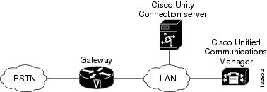
The Cisco Unified CallManager integration uses the LAN to connect Cisco Unity Connection and the phone system. The gateway provides connections to the PSTN. Figure 1 shows the connections.
Figure 1 Connections Between the Phone System and Cisco Unity Connection
Call Information
The phone system sends the following information with forwarded calls:
•
•
•
Cisco Unity Connection uses this information to answer the call appropriately. For example, a call forwarded to Cisco Unity Connection is answered with the personal greeting of the user. If the phone system routes the call to Cisco Unity Connection without this information, Cisco Unity Connection answers with the opening greeting.
Integration Functionality
The Cisco Unified CallManager integration with Cisco Unity Connection provides the following features:
•
•
•
•
•
•
The functionality of this integration may be affected by the issues described below.
Use of Cisco Unified Survivable Remote Site Telephony (SRST) Router
When a Cisco Unified Survivable Remote Site Telephony (SRST) router is part of the network and the Cisco Unified SRST router takes over call processing functions from Cisco Unified CallManager (for example, because the WAN link is down), phones at a branch office can continue to function. In this situation, however, the integration features have the following limitations:
•
•
•
•
•
•
When the Cisco Unified SRST router uses PRI/BRI connections, the caller ID for calls from a branch office to Cisco Unity Connection may be the full number (exchange plus extension) provided by the PSTN and therefore may not match the extension of the Cisco Unity Connection user. If this is the case, you can let Cisco Unity Connection recognize the caller ID by using alternate extensions.
Redirected Dialed Number Information Service (RDNIS) needs to be supported when using SRST.
For information on setting up Cisco Unified SRST routers, refer to the "Integrating Voice Mail with Cisco Unified SRST" section of the Cisco Unified SRST System Administrator Guide at http://www.cisco.com/univercd/cc/td/doc/product/software/ios122/122newft/122limit/122z/122zj15/index.htm.
Impact of Non-Delivery of RDNIS on Voice Mail Calls Routed via AAR
RDNIS needs to be supported when using Automated Alternate Routing (AAR).
AAR can route calls over the PSTN when the WAN is oversubscribed. However, when calls are rerouted over the PSTN, RDNIS can be affected. Incorrect RDNIS information can affect voice mail calls that are rerouted over the PSTN by AAR when Cisco Unity Connection is remote from its messaging clients. If the RDNIS information is not correct, the call will not reach the voice mail box of the dialed user but will instead receive the automated attendant prompt, and the caller might be asked to reenter the extension number of the party they wish to reach. This behavior is primarily an issue when the telephone carrier is unable to ensure RDNIS across the network. There are numerous reasons why the carrier might not be able to ensure that RDNIS is properly sent. Check with your carrier to determine whether it provides guaranteed RDNIS delivery end-to-end for your circuits. The alternative to using AAR for oversubscribed WANs is simply to let callers hear reorder tone in an oversubscribed condition.
(Cisco Unified CallManager 4.2(3) and Later 4.2(x) Releases Only) Impact of the Original Calling Party on Transfer Feature
For Cisco Unified CallManager 4.2(3) and later 4.2(x) releases, when the Original Calling Party on Transfer feature is enabled, the following impacts occur:
•
•
•
•
To enable the Original Calling Party on Transfer feature, in Cisco Unified CallManager Administration, on the Service Parameters Configuration page for the Cisco Unified CallManager server, you must set the Display Original Calling Number on Transfer from Cisco Unity service parameter to True.
Note that if the Original Calling Party on Transfer feature is enabled on Cisco Unified CallManager, a transfer loop can occur when the following happens:
1.
2.
3.
4.
To avoid a transfer loop under this condition, users must avoid forwarding calls to extensions that will not be answered.
Also note that if the Original Calling Party on Transfer feature is disabled on Cisco Unified CallManager, the call can be disconnected when the following happens:
1.
2.
3.
4.
To avoid disconnecting calls under this condition, users must avoid forwarding calls to extensions that will not be answered.
Integrations with Multiple Phone Systems
Cisco Unity Connection can be integrated with multiple phone systems at one time. For information on and instructions for integrating Cisco Unity Connection with multiple phone systems, refer to the Multiple Phone System Integration Guide at http://www.cisco.com/en/US/products/ps6509/products_installation_and_configuration_guides_list.html.
Planning How the Voice Messaging Ports Will Be Used by Cisco Unity Connection
Before programming the phone system, you need to plan how the voice messaging ports will be used by Cisco Unity Connection. The following considerations will affect the programming for the phone system (for example, setting up the hunt group or call forwarding for the voice messaging ports):
•
•
•
The following table describes the voice messaging port settings in Cisco Unity Connection that can be set on Telephony Integrations > Port of Cisco Unity Connection Administration.
The Number of Voice Messaging Ports to Install
The number of voice messaging ports to install depends on numerous factors, including:
•
•
•
•
•
•
•
•
It is best to install only the number of voice messaging ports that are needed so that system resources are not allocated to unused ports.
The Number of Voice Messaging Ports That Will Answer Calls
The calls that the voice messaging ports answer can be incoming calls from unidentified callers or from users. Typically, the voice messaging ports that answer calls are the busiest.
You can set voice messaging ports to both answer calls and to dial out (for example, to send message notifications). However, when the voice messaging ports perform more than one function and are very active (for example, answering many calls), the other functions may be delayed until the voice messaging port is free (for example, message notifications cannot be sent until there are fewer calls to answer). For best performance, dedicate certain voice messaging ports for only answering incoming calls, and dedicate other ports for only dialing out. Separating these port functions eliminates the possibility of a collision, in which an incoming call arrives on a port at the same time that Cisco Unity Connection takes the port off-hook to dial out.
The Number of Voice Messaging Ports That Will Only Dial Out, and Not Answer Calls
Ports that will only dial out and will not answer calls can do one or more of the following:
•
•
•
Typically, these voice messaging ports are the least busy ports.
Caution
Preparing for Programming the Phone System
Record your decisions about the voice messaging ports to guide you in programming the phone system.
Programming the Cisco Unified CallManager Phone System
After Cisco Unified CallManager software is installed, do the following procedures in the order given.
To Add Partitions and a Calling Search Space to Contain the Voice Mail Ports
Step 1
Step 2
Step 3
Step 4
Step 5
Step 6
Step 7
Step 8
Step 9
Step 10
Step 11
Step 12
The name of the partition appears in the Selected Partitions field.
Step 13
Step 14
Step 15
Step 16
Step 17
Caution
Step 18
Step 19
To Add a Device Pool for the Voice Mail Ports
Step 1
Step 2
Step 3
Step 4
In the following procedure, add a voice mail port to Cisco Unified CallManager for each voice mail port that you will connect to Cisco Unity Connection.
To Add Voice Mail Ports to Cisco Unified CallManager
Step 1
Step 2
Step 3
The voice mail server name must match the Device Name Prefix field in Cisco Unity Connection on the Port Group Basics page for the voice messaging ports.
Step 4
Step 5
If you will integrate Cisco Unity Connection with multiple clusters of Cisco Unified CallManager, the number you enter here cannot bring the total number of ports on all clusters integrated with Cisco Unity Connection to more than the number of ports enabled by the Cisco Unity Connection license.
Step 6
Step 7
Step 8
Table 4 Settings for the Voice Mail Directory Numbers Page
Beginning Directory Number
Enter the extension number of the first voice mail port.
Partition
Click the name of the partition that you set up for all voice mail port directory numbers. For example, click "VMRestrictedPT."
Calling Search Space
Click the name of a calling search space that you set up to contain the partition with all voice mail port directory numbers, as set in Step 9 of the "To Add Partitions and a Calling Search Space to Contain the Voice Mail Ports" procedure. For example, click "VMRestrictedCSS."
Because this calling search space is not used by user phones, users are not able to dial the voice mail ports. However, users can dial the voice mail pilot number.
Display
Accept the default of Voicemail.
This text appears on the phone when the pilot number is dialed.
AAR Group
Click the automated alternate routing (AAR) group for the voice mail ports. The AAR group provides the prefix digits that are used to route calls that are otherwise blocked due to insufficient bandwidth. If you click None, no rerouting of blocked calls will be attempted.
External Number Mask
Leave this field blank, or specify the mask used to format caller ID information for external (outbound) calls. The mask can contain up to 50 characters. Enter the literal digits that you want to appear in the caller ID information, and enter X for each digit in the directory number of the device.
Device Security Mode
Click the security mode that you want to use for the voice mail ports. For details on the settings for Cisco Unified CallManager authentication and encryption of the voice mail ports, see the "Appendix: Cisco Unified CallManager Authentication and Encryption of Cisco Unity Connection Voice Messaging Ports" section.
Step 9
Step 10
Step 11
If the settings are not correct, click Back and enter the correct settings.
To Add Voice Mail Ports to Line Groups
Step 1
You can also reach the line group pages by clicking Route Plan > Route/Hunt > Line Group in the Cisco Unified CallManager Administration.
Step 2
This line group will contain directory numbers for voice mail ports that will answer calls. Directory numbers for voice mail ports that will only dial out (for example, to set MWIs) must not be included in this line group.
Step 3
Step 4
Step 5
Step 6
Caution
Step 7
Caution
Step 8
Step 9
Otherwise, skip the remaining steps in this procedure and continue on to the "To Add the Line Group to a Hunt List" procedure.
Step 10
This line group will contain directory numbers for voice mail ports that will only dial out. Directory numbers for voice mail ports that answer calls must not be included in this line group.
Step 11
Step 12
Step 13
Step 14
Caution
Step 15
Caution
Step 16
To Add the Line Group to a Hunt List
Step 1
Step 2
Step 3
Step 4
Step 5
Step 6
Step 7
Caution
Step 8
Step 9
Step 10
Step 11
To Add the Hunt List to a Hunt Pilot Number
Step 1
Step 2
Step 3
Table 8 Settings for Hunt Pilot Configuration Page
Hunt Pilot
Enter the hunt pilot number for the voice mail ports. The hunt pilot number must be different from the extension numbers of the voice mail ports.
The hunt pilot number is the extension number that users enter to listen to their voice messages.
Partition
Click the name of the partition that you set up for the voice mail pilot number. For example, click "VMPilotNumberPT."
Description
Enter Cisco Unity Connection Hunt Pilot or another description.
Numbering Plan
Accept the default setting, or click the numbering plan that you have set up for your system.
Route Filter
Click None, or click the name of the route filter that you set up for your system.
MLPP Precedence
Accept the default setting, or click another setting.
Hunt List
Click the hunt list of voice mail ports that answer calls, which you set up in the "To Add the Line Group to a Hunt List" procedure.
Provide Outside Dial Tone
Uncheck the check box.
Step 4
To Specify MWI Directory Numbers
Step 1
Step 2
Step 3
Step 4
Step 5
Step 6
Step 7
In the following procedure, you will add the voice mail pilot number, which is the extension that you dial to listen to your voice messages. Your Cisco IP phone automatically dials the voice mail pilot number when you press the Messages button.
To Add a Voice Mail Pilot Number for the Voice Mail Ports
Step 1
Step 2
Step 3
Step 4
To Set Up the Voice Mail Profile
Step 1
Step 2
Step 3
Step 4
To Set Up the Voice Mail Server Service Parameters
Step 1
Step 2
Step 3
Step 4
Step 5
Step 6
Step 7
When this parameter is set to True, Cisco Unified CallManager uses any configured translation patterns to convert voice mail extensions into directory numbers when turning on or off an MWI.
Step 8
Creating a New Integration with the Cisco Unified CallManager Phone System
After ensuring that the Cisco Unified CallManager phone system and Cisco Unity Connection are ready for the integration, do the following procedures to set up the integration and to enter the port settings.
To Create an Integration
Step 1
Step 2
Step 3
Step 4
Step 5
Step 6
Step 7
Step 8
Step 9
Step 10
Step 11
Step 12
Connecting to an AXL server is needed when Cisco Unity Connection must have access to the Cisco Unified CallManager database for importing Cisco Unified CallManager users and for changing certain phone settings for users of Cisco Unity Connection personal call transfer rules.
Caution
Step 13
Step 14
Step 15
Step 16
Note
Step 17
Step 18
Note
Step 19
Step 20
a.
b.
Note
c.
Step 21
a.
b.
Note
c.
Step 22
Step 23
Note
Step 24
Step 25
Step 26
Step 27
Step 28
Step 29
Step 30
Step 31
Step 32
Step 33
Step 34
If the test is not successful, the Task Execution Results displays one or more messages with troubleshooting steps. After correcting the problems, test the connection again.
Step 35
Step 36
If you want to set up for Cisco Unified CallManager authentication and encryption, continue with the "Setting Up Cisco Unified CallManager Authentication and Encryption with Cisco Unity Connection" below.
Setting Up Cisco Unified CallManager Authentication and Encryption with Cisco Unity Connection
If you are not setting up Cisco Unified CallManager authentication and encryption, skip to the "Testing the Integration" section.
If you are setting up Cisco Unified CallManager authentication and encryption, do the following two procedures.
For additional information about authentication and encryption with Cisco Unified CallManager and Cisco Unity Connection, see the "Appendix: Cisco CallManager Authentication and Encryption of Voice Messaging Ports" section.
Caution
To Ensure That the Tftp.exe File Is Present on Cisco Unity Connection Server
Step 1
•
•
•
•
•
•
•
•
•
•
•
•
•
•
•
Step 2
Otherwise, on the Start menu, click Run.
Step 3
Step 4
Step 5
Step 6
Step 7
To Enable Cisco Unified CallManager Authentication and Encryption for Cisco Unity Connection Voice Messaging Ports
Step 1
Step 2
Step 3
Note
Step 4
Caution
Step 5
Step 6
Step 7
Cisco Unity Connection generates the voice messaging port device certificates and the Cisco Unity Connection root certificate.
Step 8
Step 9
Step 10
Step 11
Step 12
Step 13
Caution
Step 14
Step 15
•
•
Caution
Step 16
a.
b.
c.
d.
e.
f.
g.
h.
i.
j.
If the test is not successful, the Task Results list displays one or more messages with troubleshooting steps. After correcting the problems, test the connection again.
k.
Step 17
a.
b.
c.
d.
e.
f.
g.
h.
i.
If the test is not successful, the Task Results list displays one or more messages with troubleshooting steps. After correcting the problems, test the connection again.
j.
Step 18
Step 19
Testing the Integration
To test whether Cisco Unity Connection and the phone system are integrated correctly, do the following procedures in the order listed.
If any of the steps indicate a failure, refer to the following documentation as applicable:
•
•
To Set Up the Test Configuration
Step 1
Step 2
Caution
Step 3
Step 4
Step 5
Step 6
Step 7
Step 8
Step 9
Step 10
Step 11
Step 12
Step 13
Step 14
Step 15
Step 16
Step 17
Step 18
Step 19
Step 20
Do not close the Cisco Unity Connection Administration window because you will use it again in a later procedure.
Step 21
Step 22
Step 23
To Test an External Call with Release Transfer
Step 1
Step 2
Step 3
Step 4
Step 5
Step 6
Step 7
Step 8
Step 9
Step 10
To Test Listening to Messages
Step 1
Step 2
Step 3
Step 4
Step 5
Step 6
Step 7
Step 8
To Set Up Supervised Transfer on Cisco Unity Connection
Step 1
Step 2
Step 3
Step 4
Do not close the Cisco Unity Connection Administration window because you will use it again in a later procedure.
To Test Supervised Transfer
Step 1
Step 2
Step 3
Step 4
Step 5
Step 6
Step 7
Step 8
Step 9
To Delete the Test User
Step 1
Step 2
Step 3
If Cisco Unity Connection is set up for Cisco Unified CallManager authentication or encryption, do the following procedure.
To Test Cisco Unified CallManager Authentication and Encryption
Step 1
Step 2
Step 3
(Multiple Integrations Only) Adding New User Templates
When you create the first phone system integration, this phone system is automatically selected in the default user template. The users that you add after creating this phone system integration will be assigned to this phone system by default.
However, for each additional phone system integration that you create, you must add the applicable new user templates that will assign users to the new phone system. You must add the new templates before you add new users who will be assigned to the new phone system.
For details on adding new user templates, refer to the "Adding, Changing, or Deleting an Account Template" chapter in the Cisco Unity Connection User Moves, Adds, and Changes Guide at http://www.cisco.com/en/US/products/ps6509/prod_maintenance_guides_list.html.
For details on selecting a user template when adding a new user, refer to the applicable chapter for adding user accounts in the Cisco Unity Connection User Moves, Adds, and Changes Guide at http://www.cisco.com/en/US/products/ps6509/prod_maintenance_guides_list.html.
Changing the Number of Voice Messaging Ports
To change the number of voice messaging ports in Cisco Unified CallManager and in Cisco Unity Connection for an existing integration, do the following procedures.
To Change the Number of Voice Mail Ports in Cisco Unified CallManager Administration
Step 1
•
•
If you are adding voice messaging ports, do the "To Add Voice Messaging Ports in Cisco Unity Connection Administration" procedure.
If you are deleting voice messaging ports, do the "To Delete Voice Messaging Ports in Cisco Unity Connection Administration" procedure.
To Add Voice Messaging Ports in Cisco Unity Connection Administration
Step 1
Step 2
Step 3
Step 4
Step 5
Step 6
Step 7
Step 8
Step 9
Step 10
Step 11
Caution
Step 12
Step 13
Step 14
If you are using Cisco Unified CallManager authentication and encryption, in Cisco Unity Connection Administration, expand Telephony Integrations, then click Phone System.
Caution
Step 15
Step 16
Step 17
Step 18
Step 19
Caution
Step 20
Step 21
•
•
Caution
Step 22
a.
b.
c.
d.
e.
f.
g.
h.
i.
j.
Step 23
a.
b.
c.
d.
e.
f.
g.
h.
i.
Step 24
If the test is not successful, the Task Execution Results displays one or more messages with troubleshooting steps. After correcting the problems, test the connection again.
Step 25
Step 26
To Delete Voice Messaging Ports in Cisco Unity Connection Administration
Step 1
Step 2
Step 3
Step 4
Step 5
Step 6
Step 7
Step 8
If the test is not successful, the Task Execution Results displays one or more messages with troubleshooting steps. After correcting the problems, test the connection again.
Step 9
Step 10
Adding a Cisco Unified CallManager Express Server to a Cisco Unified CallManager Phone System Integration
Cisco Unity Connection can integrate a Cisco Unified CallManager phone system integration that has a port group of Cisco Unified CallManager servers and a port group of a Cisco Unified CallManager Express server. This configuration is typically used to ensure call processing functionality at a branch office when the WAN link is down.
There are, however, the following considerations:
•
•
•
•
To add a Cisco Unified CallManager Express server to a Cisco Unified CallManager phone system integration, do the following procedure.
To Add a Cisco Unified CallManager Express Server to a Cisco Unified CallManager Phone System Integration
Step 1
Step 2
Step 3
Step 4
Step 5
Step 6
Step 7
Note
Step 8
Step 9
Step 10
Step 11
Step 12
Step 13
Table 24 Settings for the New Port Page
Number of Ports
Enter the number of voice messaging ports that you want to create on Cisco Unity Connection for connecting to the Cisco Unified CallManager Express server.
Phone System
Click the display name of the Cisco Unified CallManager phone system integration.
Port Group
Click the display name of the port group that you created for the Cisco Unified CallManager Express server in Step 5.
Step 14
Step 15
Note
Step 16
Step 17
Step 18
Step 19
Step 20
Step 21
Step 22
Step 23
If the test is not successful, the Task Execution Results displays one or more messages with troubleshooting steps. After correcting the problems, test the connection again.
Step 24
Step 25
Appendix: Cisco Unified CallManager Authentication and Encryption of Cisco Unity Connection Voice Messaging Ports
A potential point of vulnerability for a Cisco Unity Connection system is the connection between Cisco Unity Connection and Cisco Unified CallManager. Possible threats include:
•
•
•
•
•
•
Cisco Unified CallManager Security Features
Cisco Unified CallManager 4.1(3) or later can secure the connection with Cisco Unity Connection against these threats. The Cisco Unified CallManager security features that Cisco Unity Connection can take advantage of are described in Table 26.
Authentication and signaling encryption serve as the minimum requirements for media encryption; that is, if the devices do not support signaling encryption and authentication, media encryption cannot occur.
Note
Functional Overview
The security features (authentication and encryption) between Cisco Unity Connection and Cisco Unified CallManager require the following:
•
•
•
The process of authentication and encryption of Cisco Unity Connection voice messaging ports is as follows:
1.
2.
3.
4.
Behavior for Calls
When a call is made between Cisco Unity Connection and Cisco Unified CallManager, the call-signaling messages and the media stream are handled in the following manner:
•
•
•
Security Mode Settings in Cisco Unity Connection
The Security Mode settings in Cisco Unity Connection Administration determine how the ports handle call-signaling messages and whether encryption of the media stream is possible. Table 27 describes the effect of the Security Mode settings on the Telephony Integrations > Port > Port Basics page for each port.
Disabling and Re-Enabling Security
The authentication and encryption features between Cisco Unity Connection and Cisco Unified CallManager can be enabled and disabled by changing the Security Mode for all Cisco Unified CallManager clusters to Non-Secure, and by changing the applicable settings in the Cisco Unified CallManager Administration.
Authentication and encryption can be re-enabled by changing the Security Mode to Authenticated or Encrypted.
Note
Multiple Clusters Can Have Multiple Settings
When Cisco Unity Connection has multiple Cisco Unified CallManager phone system integrations, each Cisco Unified CallManager phone system integration can have different Security Mode settings. For example, one Cisco Unified CallManager phone system integration can be set to Encrypted, and a second Cisco Unified CallManager phone system integration can be set to Non-Secure.
Settings for Individual Voice Messaging Ports
For troubleshooting purposes, authentication and encryption for Cisco Unity Connection voice messaging ports can be individually enabled and disabled. At all other times, we recommend that the Security Mode setting for all individual voice messaging ports in a Cisco Unified CallManager port group be the same.
Appendix: Documentation and Technical Assistance
Conventions
The Cisco Unified CallManager 4.3 Integration Guide for Cisco Unity Connection 1.1 uses the following conventions.
The Cisco Unified CallManager 4.3 Integration Guide for Cisco Unity Connection 1.1 also uses the following conventions:
Note
Caution
For descriptions and URLs of Cisco Unity Connection documentation on Cisco.com, see the About Cisco Unity Documentation. The document is shipped with Cisco Unity Connection and is available at http://www.cisco.com/en/US/products/ps6509/products_documentation_roadmaps_list.html.
Obtaining Documentation, Obtaining Support, and Security Guidelines
For information on obtaining documentation, obtaining support, providing documentation feedback, security guidelines, and also recommended aliases and general Cisco documents, see the monthly What's New in Cisco Product Documentation, which also lists all new and revised Cisco technical documentation, at:
http://www.cisco.com/en/US/docs/general/whatsnew/whatsnew.html
Any Internet Protocol (IP) addresses used in this document are not intended to be actual addresses. Any examples, command display output, and figures included in the document are shown for illustrative purposes only. Any use of actual IP addresses in illustrative content is unintentional and coincidental.
© 2007 Cisco Systems, Inc. All rights reserved.