Table Of Contents
H.320 Video - ISO/IEC-13871 Bonding
Contents
Prerequisites for H.320 Video - ISO/IEC-13871 Bonding
Restrictions for H.320 Video - ISO/IEC-13871 Bonding
Information About H.320 Video - ISO/IEC-13871 Bonding
How to Configure H.320 Video - ISO/IEC-13871 Bonding
Configuring the Ethernet Interface for H.323 VoIP Packets
Configuring the Incoming POTS Dial-peer for Calls from an H.320 Video Endpoint to an IP Video Terminal
Configuring the Outgoing VoIP Dial-peer for Calls from a H.320 Video Endpoint to an IP Video Terminal
Configuring the Incoming VoIP Dial-peer for Calls from an IP Video Terminal to an H.320 Video Endpoint
Configuring the Outgoing POTS Dial-Peer for Calls from an IP Video Terminal to an H.320 Video Endpoint
Configuring Required Voice Class Called Number Pools for Secondary Number Allocation
Configuring the PRI or BRI Trunk for H.320 Video
Additional References
Related Documents
International Telecommunication Union Standards
MIBs
Internet Engineering Task Force Request for Comments
International Organization for Standardization Standards
Technical Assistance
Command Reference
debug voip h221
Feature Information for H.320 Video - ISO/IEC-13871 Bonding
H.320 Video - ISO/IEC-13871 Bonding
Last Updated: September 6, 2010
H.320 Video - ISO/IEC-13871 Bonding adds ISO-13871 bonding for H.320 terminals to the Cisco IOS gateway. Bonding provides channel aggregation in video conferencing using ISDN.
Finding Feature Information in This Module
Your Cisco IOS software release may not support all of the features documented in this module. To reach links to specific feature documentation in this module and to see a list of the releases in which each feature is supported, use the "Feature Information for H.320 Video - ISO/IEC-13871 Bonding" section.
Finding Support Information for Platforms and Cisco IOS and Catalyst OS Software Images
Use Cisco Feature Navigator to find information about platform support and Cisco IOS and Catalyst OS software image support. To access Cisco Feature Navigator, go to http://www.cisco.com/go/cfn. An account on Cisco.com is not required.
Contents
• Prerequisites for H.320 Video - ISO/IEC-13871 Bonding
•Information About H.320 Video - ISO/IEC-13871 Bonding
•How to Configure H.320 Video - ISO/IEC-13871 Bonding
•Additional References
•Command Reference
•Feature Information for H.320 Video - ISO/IEC-13871 Bonding
Prerequisites for H.320 Video - ISO/IEC-13871 Bonding
Before you configure H.320 Video - ISO/IEC-13871 Bonding, you must do the following:
•Ensure that you have a Cisco IOS image that supports this feature. Access Cisco Feature Navigator at http://www.cisco.com/go/cfn
•Configure ISDN PRI voice interface support or ISDN BRI voice interface support (or what you are using for BRI). See Basic ISDN Voice-Interface Configuration.
•Ensure that the ISDN layer is up. Use the show isdn status command to display the current status of each ISDN layer.
•Set T1/E1 clocking. Use the network-clock-select command to name a source to provide timing for the network clock and to specify the selection priority for this clock source.
Supported Routers, Hardware Modules, and Codecs
•This feature supports the following routers:
–Cisco 2600XM
–Cisco 2800 series
–Cisco 3700 series
–Cisco 3800 series
•This feature supports the following hardware modules:
–NM-HDV2
–NM-HD-xx
–Onboard DSP module
–VIC2-2BRI
–VWIC-xMFT-x
–VWIC2-xMFT-x
•This feature supports the following video codecs:
–ITU-T Recommendation H.261
–ITU-T Recommendation H.263
–ITU-T Recommendation H.263+
–ITU-T Recommendation H.264 (only packetization described by ITU-T H.241 Annex A/RFC3984 packetization-mode 0 is supported)
•This feature supports the following audio codecs:
–ITU-T Recommendation G.711 (u-law/A-law)
–ITU-T Recommendation G.722 (64K, 56K, and 48K)
–ITU-T Recommendation G.728
–ITU-T Recommendation G.729
Tested Endpoints
This feature has been tested with the following Endpoints:
Table 1 Tested Endpoints
Endpoint Type
|
Software Version
|
Polycom HDX 8000 HD
|
2.5.0.2-3395
|
Polycom HDX 4000 HD
|
2.5.0.6-3955
|
Polycom VSX 7000
|
8.5
|
Polycom VSX 3000
|
7.5
|
Tandberg 1000
|
E3.0, E4.1, and E6.1
|
Supported Topologies
See How to Configure H.320 Video - ISO/IEC-13871 Bonding.
Restrictions for H.320 Video - ISO/IEC-13871 Bonding
The following restrictions are for H.320 Video - ISO/IEC-13871 Bonding:
•H.320 calls between a Cisco H.320 gateway and a Cisco IPVC only support bandwidths of 64K-384 Kbps, 512 Kbps, and 768 Kbps. These speeds are defined in Table A1 of H.221. The Cisco IPVC has no support for speeds defined in Table A6 of H.221, which include 448 Kbps, 576 Kbps-704Kbps, and 832Kbps-1024Kbps.
Bandwidth can be set to any valid value (64Kpbs increments) in the range of 64 K to 1024 Kbps in the Cisco H.320 Gateway when connected to an IPVC. The H.320 call falls back to the highest speed the IPVC can support. For example, if the configured bandwidth is 702 Kbps (11B), the call connects at 512 Kbps. If the bandwidth is configured for 1024 Kbps, the call connects at 768 Kbps.
A Cisco gateway with H.320 Video - ISO/IEC-13871 Bonding connected to a T1/E1 Polycom 7000/8000 or equivalent device that supports H.221Table A6, can connect an H.320 call at any speed in the range of 64K and 1024 Kbps.
A Cisco gateway with H.320 Video - ISO/IEC-13871 Bonding that is connected to an H.320 device, which supports H.221 Table A6, for example T1/E1 Polycom 7000/8000, can connect an H.320 call at any speed in the range of 64K to 1024 Kbps, in 64 Kbps increments.
•Table 4 shows the maximum bandwidth to DSP channel requirements for ISO-13871 Bonding for H.320 terminals.
When DSP channels required for maximum requested bandwidth are not available, the dial-peer bandwidth configuration defines the behavior.
The following is a configuration for an incoming dial-peer:
dial-peer voice 415027 pots
incoming called-number 415027
bandwidth maximum 384 minimum 384
With this configuration, a video call always requires 6 DSP channels (384/64 = 6 DSPs) to successfully add video (max=min bandwidth). If there are only 1 to 5 DSP channels available, a video H.320 call only connects as a single-channel H.320 voice call. This effect happens whenever the minimum bandwidth selection is greater than the available DSP channels, as shown by the show voice dsp | begin H32 command:
router# show voice dsp | b H32
DSP DSP TX/RX DSPWARE CURR PAK TX/RX
TYPE NUM CH CODEC VERSION STATE VOICEPORT TS ABRT PACK COUNT
===== === === =================== ========== ===== ========= == ==== ============
C5510 003 01 h320p(01) 23.0.502 busy 1/0:15 01
003 01a g711ulaw 23.0.502 busy 0 3467/1743
------------------------END OF FLEX VOICE CARD 1 ----------------------------
By changing the minimum value to 64 (see the dial-peer in the next example), the behavior would be to use the maximum number of DSP channels available, up to the value of the bandwidth maximum for video. In this case, if 2 DSP channels are available, then a 2B (128 Kbps) H.320 video call is attempted. If 3 DSP channels are available, then a 3B (192Kbps) H.320 video call is attempted. The cases for 4, 5, or 6(+) DSP channels are identical. If only one DSP channel is available, it always results in an H.320 audio only call.
dial-peer voice 415027 pots
incoming called-number 415027
* Since the default value for the minimum is 64, it does not appear in the running
configuration when it is set
This effect is the same whether the dial-peer is incoming or outgoing, and does not take into account how the remote end may be configured.
Table 2 Maximum Bandwidth to DSP Channels Requirements
Maximum Bandwidth
|
DSP Channels
|
1024 K
|
16
|
960
|
15
|
896
|
14
|
832
|
13
|
768
|
12
|
704
|
11
|
640
|
10
|
576
|
9
|
512k
|
8
|
448
|
7
|
384
|
6
|
320
|
5
|
256
|
4
|
192
|
3
|
128
|
2
|
•Restrictions with third-party endpoints:
The number of digits passed in the IC frame for secondary calls is limited to 7 digits, unless the endpoint can support Annex C of ISO/IEC-13871. If Annex C is not supported, the number of digits passed can be less than or equal to 7, and not more than 7.
The called number of the secondary call must have the same length as the called number of the primary call.
•No Overlapping of Secondary Numbers
If a router has the voice pool defined as voice class called number pool 10 index 1 0101 - 0105, then:
1. H.320 call A arrives with the primary called number 5550100 from a video call of 384K and number pool 10 is used.
2. A problem can occur if H.320 Call A is in the process of secondary call leg setup, and a new H.320 call arrives (Call B) with the primary called number of 5550101. The primary call leg of Call B is included as part of Call A, because the Ciscogateway is looking for an H.320 call leg with the last 4 digits of 0101 for Call A. This results in both calls failing. This is extremely rare, and can be reduced or eliminated by doing the following:
–Use as many significant digits in the definition of the call number pool as possible. For example voice class called number pool 10 index 1 5550101 - 5550105 is much better than voice class called number pool 10 index 1 0101 - 01005 for the above example. If the numbers are unique to the call number pool, then the problem cannot occur.
–Annex C of ISO/IEC-13871 allows more than 7 significant digits to be passed during secondary number exchange. If the H.320 video terminal being connected to the Cisco H.320 Gateway supports Annex C, use it.
Note This scenario occurs only during the bonding phase; if Call A completed the call setup phase of bonding and then Call B arrives, there is no overlapping of secondary numbers.
•Far end camera control (FECC) is not supported.
–On the ISDN H.320 side, an LSD, HSD, or MLP data channel must be opened to pass the FECC data.
–Cisco IOS H.320 gateway does not support FECC. One audio stream and one video stream are supported but no data channels are supported.
Information About H.320 Video - ISO/IEC-13871 Bonding
The most widely used method to create an H.320 call is to use ISO/IEC-13871 (mode 1) for channel setup. This standard specifies a method for creating a multirate bonded data call over 64K/56K B-channel networks. ISO-13871 specifies the method to pass a secondary leg called number and a method to calculate relative delay between the channels. The secondary B-channels are setup during this time although ISO-13871 does not specify how this is to be done (ISDN/SS7/MFCR2, and so on). When all channels are up and the delay is established, mode 1 specifies that ISO-13871 is now finished. It is important to note that ISO-13871 does not say anything about how the multirate data call is to be used.
For the H.320 case, the newly created multirate data call is to be used for an H.320 video call. When ISO-13871 mode 1 is dropped, H.221 FAS/BAS is established on the primary B-channel. The secondary channels are 64K clear channels. Using the ITU-T H.221/H.242 specifications, capabilities and mode information is now passed between the H.320 peer device and the H.320 gateway.
When you configure isdn incoming-voice voice on a terminating gateway and an originating gateway, with one side set up for H.320 (information-type video) and the other side treating calls strictly as data or clear channel calls, the terminating gateway opens a DSP channel as an H.320 bonding call with the Initial IC message specified in the last 16 bytes.
When this channel is opened, the DSP sends the Initial IC message continuously to the ISDN B-channel (only one is opened at this point) until the host tells it to do otherwise. After a timeout period of 3 to 10 seconds, the ISDN is disconnected, and the DSP channel is closed.
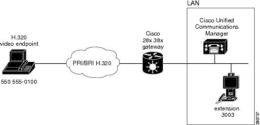
How to Configure H.320 Video - ISO/IEC-13871 Bonding
This section describes how to configure H.320 Video - ISO/IEC-13871 Bonding to support the topology shown, and includes the following tasks:
•Configuring the Ethernet Interface for H.323 VoIP Packets
•Configuring the Incoming POTS Dial-peer for Calls from an H.320 Video Endpoint to an IP Video Terminal
•Configuring the Outgoing VoIP Dial-peer for Calls from a H.320 Video Endpoint to an IP Video Terminal
•Configuring the Incoming VoIP Dial-peer for Calls from an IP Video Terminal to an H.320 Video Endpoint
•Configuring the Outgoing POTS Dial-Peer for Calls from an IP Video Terminal to an H.320 Video Endpoint
•Configuring Required Voice Class Called Number Pools for Secondary Number Allocation
•Configuring the PRI or BRI Trunk for H.320 Video
Figure 1 Topology for H.320 Bonding
Configuring the Ethernet Interface for H.323 VoIP Packets
Use this procedure to configure the Ethernet interface for H.323 VoIP packets.
SUMMARY STEPS
1. enable
2. configure terminal
3. interface ethernet slot/port
4. ip address ip-address mask
5. exit
DETAILED STEPS
| |
Command or Action
|
Purpose
|
Step 1
|
enable
Example:
Router> enable
|
Enables privileged EXEC mode.
•Enter your password if prompted.
|
Step 2
|
configure terminal
Example:
Router# configure terminal
|
Enters global configuration mode.
|
Step 3
|
interface ethernet slot/port
Example:
Router(config)# interface Ethernet0/0
|
Enters interface configuration mode by specifying the Ethernet interface that you want to configure.
|
Step 4
|
ip address ip-address mask
Example:
Router(config-if)# ip address 209.165.200.225
255.255.255.224
|
Sets a primary or secondary IP address for an interface.
|
Step 5
|
exit
Example:
Router(config-if)# exit
|
Exits interface configuration mode.
|
Configuring the Incoming POTS Dial-peer for Calls from an H.320 Video Endpoint to an IP Video Terminal
Use this procedure to configure the incoming POTS dial-peer for calls from an H.320 video endpoint to an IP video terminal.
SUMMARY STEPS
1. enable
2. configure terminal
3. dial-peer voice tag pots
4. information-type [fax | video | voice]
5. incoming called-number string
6. bandwidth maximum value [minimum value]
7. direct-inward-dial
8. end
DETAILED STEPS
| |
Command or Action
|
Purpose
|
Step 1
|
enable
Example:
Router> enable
|
Enables privileged EXEC mode.
•Enter your password if prompted.
|
Step 2
|
configure terminal
Example:
Router# configure terminal
|
Enters global configuration mode.
|
Step 3
|
dial-peer voice tag pots
Example:
Router(config)# dial-peer voice 500 pots
|
Defines a particular dial peer, specifies the method of voice encapsulation, and enters dial-peer configuration mode.
|
Step 4
|
information-type video
Example:
Router(config-dial-peer)# information-type
video
|
Selects the POTS dial-peer to be a video dial-peer.
Without this setting, the dial-peer acts as a plain voice dial-peer.
|
Step 5
|
incoming called-number [+]string[T]
Example:
Router(config-dial-peer)# incoming
called-number 5550104
|
Specifies a digit string that can be matched by an incoming call to associate the call with a dial peer.
|
Step 6
|
bandwidth maximum value [minimum value]
Example:
Router(config-dial-peer)# bandwidth maximum 384
minimum 64
|
Sets the maximum/minimum bandwidth on a POTS dial peer for an H.320 call.
|
Step 7
|
direct-inward-dial
Example:
Router(config-dial-peer)# direct-inward-dial
|
Enables the direct inward dialing (DID) call treatment for an incoming called number.
|
Step 8
|
end
Example:
Router(config)# end
|
Exits current configuration mode and returns to global configuration mode.
|
Configuring the Outgoing VoIP Dial-peer for Calls from a H.320 Video Endpoint to an IP Video Terminal
Use this procedure to configure the outgoing VoIP dial-peer for calls from an H.320 video endpoint to an IP video terminal.
SUMMARY STEPS
1. enable
2. configure terminal
3. dial-peer voice tag voip
4. destination pattern [+] string [T] (outgoing dial peer)
5. video codec [h261 | h263 | h263+ | h264]
6. session target ipv4:destination address
7. codec codec-type
8. end
DETAILED STEPS
| |
Command or Action
|
Purpose
|
Step 1
|
enable
Example:
Router> enable
|
Enables privileged EXEC mode.
•Enter your password if prompted.
|
Step 2
|
configure terminal
Example:
Router# configure terminal
|
Enters global configuration mode.
|
Step 3
|
dial-peer voice tag voip
Example:
Router(config)# dial-peer voice 300 voip
|
Defines a particular dial peer, specifies the method of voice encapsulation, and enters dial-peer configuration mode.
|
Step 4
|
destination-pattern [+]string[T]
Example:
router(config-dial-peer)# destination-pattern
5550104
|
Specifies either the prefix or the full E.164 telephone number to be used for a dial peer.
|
Step 5
|
video codec {h261 | h263 | h263+ | h264
Example:
Router(config-dial-peer)# video codec h263
|
Filters out all video codecs, except the one specified in the command, from the exchanged video capabilities in both directions.
The video codec can also be used under the codec class command. If a codec class is substituted, then all of the video codecs in the class are allowed in the capabilities.
|
Step 6
|
session target ipv4:destination-address
Example:
Router(config-dial-peer)# session target
ipv4:209.165.200.225
|
Designates a network-specific address to receive calls from a VoIP dial peer.
|
Step 7
|
codec codec
Example:
Router(config-dial-peer)# codec g711ulaw
|
Filters out all audio codecs, except the one specified in the command, from the exchanged audio capabilities in both directions.
The codec can also be used under the codec class command. If a codec class is substituted, then all of the audio codecs in the class are allowed in the capabilities.
|
Step 8
|
end
Example:
Router(config)# end
|
Exits current configuration mode and returns to global configuration mode.
|
Configuring the Incoming VoIP Dial-peer for Calls from an IP Video Terminal to an H.320 Video Endpoint
Use this optional procedure to configure the incoming VoIP dial-peer for calls from an IP Video terminal to an H.320 video endpoint. Do this step only if a video codec filter or audio codec filter is needed.
SUMMARY STEPS
1. enable
2. configure terminal
3. dial-peer voice tag voip
4. incoming called-number string
5. video codec [h261 | h263 | h263+ | h264]
6. codec codec-type
7. end
DETAILED STEPS
| |
Command or Action
|
Purpose
|
Step 1
|
enable
Example:
Router> enable
|
Enables privileged EXEC mode.
•Enter your password if prompted.
|
Step 2
|
configure terminal
Example:
Router# configure terminal
|
Enters global configuration mode.
|
Step 3
|
dial-peer voice tag voip
Example:
Router(config)# dial-peer voice 301 voip
|
Defines a particular dial peer, specifies the method of voice encapsulation, and enters dial-peer configuration mode.
|
Step 4
|
incoming called-number [+]string[T]
Example:
Router(config-dial-peer)# incoming
called-number 5550104
|
Specifies either the prefix or the full E.164 telephone number to be used for a dial peer.
|
Step 5
|
video codec {h261 | h263 | h263+ | h264
Example:
Router(config-dial-peer)# video codec h263
|
Filters out all video codecs, except the one specified in the command, from the exchanged video capabilities in both directions.
The video codec can also be used under the codec class command. If a codec class is substituted, then all of the video codecs in the class are allowed in the capabilities.
|
Step 6
|
codec codec
Example:
Router(config-dial-peer)# codec g711ulaw
|
Filters out all audio codecs, except the one specified in the command, from the exchanged audio capabilities in both directions.
The codec can also be used under the codec class command. If a codec class is substituted, then all of the audio codecs in the class are allowed in the capabilities.
|
Step 7
|
end
Example:
Router(config)# end
|
Exits current configuration mode and returns to global configuration mode.
|
Configuring the Outgoing POTS Dial-Peer for Calls from an IP Video Terminal to an H.320 Video Endpoint
Use this procedure to configure the outgoing POTS dial-peer for calls from an IP video terminal to an H.320 video endpoint.
SUMMARY STEPS
1. enable
2. configure terminal
3. dial-peer voice tag pots
4. destination pattern [+] string [T] (outgoing dial peer)
5. information-type [fax | video | voice]
6. bandwidth maximum value [minimum value]
7. port slot/port:D-channel-number
8. forward-digits num-digit | all | extra
9. end
DETAILED STEPS
| |
Command or Action
|
Purpose
|
Step 1
|
enable
Example:
Router> enable
|
Enables privileged EXEC mode.
•Enter your password if prompted.
|
Step 2
|
configure terminal
Example:
Router# configure terminal
|
Enters global configuration mode.
|
Step 3
|
dial-peer voice tag pots
Example:
Router(config)# dial-peer voice 101 pots
|
Defines a particular dial peer, specifies the method of voice encapsulation, and enters dial-peer configuration mode.
|
Step 4
|
destination-pattern [+]string[T]
Example:
router(config-dial-peer)# destination-pattern
5105550103
|
Specifies either the prefix or the full E.164 telephone number to be used for a dial peer.
|
Step 5
|
information-type video
Example:
Router(config-dial-peer)# information-type
video
|
Selects the POTS dial-peer to be a video dial-peer. Without this setting, the dial-peer acts as a plain voice dial-peer.
|
Step 6
|
bandwidth maximum value [minimum value]
Example:
Router(config-dial-peer)# bandwidth maximum 384
minimum 64
|
Sets the maximum/minimum bandwidth on a POTS dial peer for an H.320 call in dial peer configuration mode.
|
Step 7
|
port controller-number:D
Example:
Router(config-dial-peer)# port 1/0:23
|
Associates a dial peer with a specific voice port.
|
Step 8
|
forward-digits all
Example:
Router(config-dial-peer)# forward-digits all
|
Specifies which digits to forward for voice calls.
|
Step 9
|
end
Example:
Router(config)# end
|
Exits current configuration mode and returns to global configuration mode.
|
Configuring Required Voice Class Called Number Pools for Secondary Number Allocation
Use this procedure to configure the numbers used in the secondary call leg setup. This is needed for incoming H.320 calls only. Outgoing H.320 calls receive the secondary call leg numbers from the connected H.320 endpoint.
SUMMARY STEPS
1. enable
2. configure terminal
3. voice class called number pool tag
4. index number called-number
5. exit
6. voice-port slot/port:D-channel-number
7. voice-class called-number-pool tag
DETAILED STEPS
| |
Command or Action
|
Purpose
|
Step 1
|
enable
Example:
Router> enable
|
Enables privileged EXEC mode.
•Enter your password if prompted.
|
Step 2
|
configure terminal
Example:
Router# configure terminal
|
Enters global configuration mode.
|
Step 3
|
voice class called number pool tag
Example:
Router(config)# voice class called number pool
100
|
Defines a voice class called number or range of numbers.
|
Step 4
|
index number called-number
Example:
router(conf-voi-serv)# index 1 5550105 -
5550120
|
Defines one or more numbers for a voice class called number.
To define numbers individually use the index x nnn version of the command.
To define a range of numbers in the pool, use the index x aaa - bbb version.
|
Step 5
|
exit
Example:
Router(config-if)# exit
|
Exits interface configuration mode.
|
Step 6
|
voice-port {slot-number/subunit-number/port |
slot/port:ds0-group-no}
Example:
Router(config)# voice-port 1/0:23
|
Enters voice-port configuration mode.
|
Step 7
|
voice-class called-number-pool tag
Example:
Router(config)# voice-class called-number-pool
100
|
Assigns a previously defined voice class called number pool to a voice port.
|
Step 8
|
end
Example:
Router(config)# end
|
Exits current configuration mode and returns to global configuration mode.
|
Configuring the PRI or BRI Trunk for H.320 Video
Use this procedure to configure the PRI or BRI trunk for H.320 video.
SUMMARY STEPS
1. enable
2. configure terminal
3. controller e1/t1 slot/port
4. framing sf | esf
5. linecode ami | b8zs
6. pri-group timeslots range
7. interface bri slot/port
8. no ip address
9. isdn switch-type
10. isdn protocol-emulate network
11. isdn layer1-emulate [user | network]
12. isdn skipsend-idverify
13. isdn integrate calltype all
14. trunk-group name
DETAILED STEPS
| |
Command or Action
|
Purpose
|
Step 1
|
enable
Example:
Router> enable
|
Enables privileged EXEC mode.
•Enter your password if prompted.
|
Step 2
|
configure terminal
Example:
Router# configure terminal
|
Enters global configuration mode.
|
| |
Configuration steps for a PRI interface
|
Step 3
|
controller e1/t1 slot/port
Example:
Router(config)# controller T1 1/0
|
Configures an E1/T1 controller and enters controller configuration mode.
|
Step 4
|
framing {sf | esf}
Example:
Router(config-controller)# framing esf
|
Select the frame type for the T1 data line.
|
Step 5
|
linecode {ami | b8zs}
Example:
Router(config-controller)# linecode b8zs
|
Use the linecode controller command to select the line-code type for a T1 line.
|
Step 6
|
pri-group timeslots range
Example:
Router(config-controller)# pri-group timeslots
1-24
|
Specifies an ISDN PRI group on a channelized T1 controller.
|
| |
Configuration steps for a BRI interface
|
Step 7
|
interface bri slot/port
Example:
Router(config)# interface BRI0/0/0
|
Configures a BRI interface and enters interface configuration mode in global configuration mode.
|
Step 8
|
ip address
Example:
Router(config-if)# no ip address
|
Sets a primary or secondary IP address for an interface. To remove an IP address or disable IP processing, use the no form of this command.
|
Step 9
|
isdn switch-type
Example:
router(config-if)# isdn switch-type basic-net3
|
Sets the ISDN switch type for the ISDN interface.
|
Step 10
|
isdn protocol-emulate [user | network]
Example:
Router(config-if)# isdn protocol-emulate
network
|
Configures the router PRI interface to serve as either the primary slave or the primary master.
|
Step 11
|
isdn layer1-emulate {user | network}
Example:
Router(config-if)# isdn layer1-emulate network
|
Configures the Layer 1 operation of a BRI voice port as clock master (NT) or slave (TE) in interface configuration mode.
|
Step 12
|
isdn skipsend-idverify
Example:
Router(config-if)# isdn skipsend-idverify
|
Stops the user side of a BRI interface from sending ID verify information in interface configuration mode.
|
Step 13
|
isdn integrate calltype all
Example:
Router(config-if)# isdn integrate calltype all
|
Enables integrated mode on an ISDN BRI or PRI interface in interface configuration mode.
|
Step 14
|
trunkgroup name preference-num (optional)
Example:
Router(config-if)# trunk-group 1
|
Assigns an analog voice port to a trunk group in voice-port configuration mode.
|
Additional References
The following sections provide references related to H.320 Bonding.
Related Documents
International Telecommunication Union Standards
Standard
|
Title
|
ITU-T E.164
|
The international public telecommunication numbering plan.
|
ITU-T H.221
|
Frame structure for a 64 to 1920 kbps channel in audiovisual teleservices.
|
ITU-T H.242
|
System for establishing communication between audiovisual terminals using digital channels up to 2 MB per second (Mbps).
|
ITU-T H.242 Amendment 1
|
Support for 14 kHz audio bandwidth extension of G.722.1 Annex C in H.242.
|
ITU-T H.261
|
Video codec for audiovisual services where data rates are multiples of 64 kbps.
|
ITU-T H.263
|
Video coding for low bit rate communication.
|
ITU-T H.263+
|
Enhancements and improved performance for H.263 video codec.
|
ITU-T H.264
|
Advanced video coding for generic audiovisual services.
|
ITU-T H.320
|
Narrow-band visual telephone systems and terminal equipment.
|
MIBs
MIB
|
MIBs Link
|
CISCO-VOICE-COMMON-DIAL-CONTROL-MIB
|
To locate and download MIBs for selected platforms, Cisco IOS releases, and feature sets, use Cisco MIB Locator found at the following URL:
http://www.cisco.com/go/mibs
|
CISCO-VOICE-DIAL-CONTROL-MIB
|
CISCO-H320-DIAL-CONTROL-MIB
|
Internet Engineering Task Force Request for Comments
International Organization for Standardization Standards
ISO
|
Title
|
ISO/IEC-13871
|
Information technology - Telecommunications and information exchange between systems - Private telecommunications networks - Digit channel aggregation
|
Technical Assistance
Description
|
Link
|
The Cisco Support website provides extensive online resources, including documentation and tools for troubleshooting and resolving technical issues with Cisco products and technologies.
To receive security and technical information about your products, you can subscribe to various services, such as the Product Alert Tool (accessed from Field Notices), the Cisco Technical Services Newsletter, and Really Simple Syndication (RSS) Feeds.
Access to most tools on the Cisco Support website requires a Cisco.com user ID and password.
|
http://www.cisco.com/techsupport
|
Command Reference
The following command is modified in the feature documented in this module. For information about all Cisco IOS commands, use the Command Lookup Tool at http://tools.cisco.com/Support/CLILookup or the Cisco IOS Master Command List, All Releases, at http://www.cisco.com/en/US/docs/ios/mcl/allreleasemcl/all_book.html.
Modified Commands
•debug voip h221
debug voip h221
To debug video call control information, use the debug voip/voice h221 command in privileged EXEC mode. To disable debugging output, use the no form of this command.
debug voip h221 [all | function | inout | default | individual [number] | message | error [ software
[ informational] | call [informational]]]
Syntax Description
all
|
(Optional) Enable all H221 debugging.
|
default
|
(Optional) Activates inout, error, and function debugs.
|
error
|
(Optional) Enable H221 error debugging.
|
function
|
(Optional) Procedure tracing.
|
individual
|
(Optional) Activation of individual H221 debugs. See Table 4.
|
inout
|
(Optional) Subsystem inout debugging.
|
raw
|
(Optional) Display Raw H.221 BAS messages.
|
raw decode
|
(Optional) Displays either ISO-13871 bonding information channel frames or H.221 BAS in a decode text format.
|
Command Modes
Privileged EXEC
Command History
Release
|
Modification
|
12.4(8)T
|
This command was introduced.
|
12.4(20)T
|
The command option raw decode was modified to also display ISO/IEC-13871 Information Channel Frames during bonding setup. No change to the command structure was done.
The command option individual had several additional indexes added for support of ISO/IEC-13871 (see Table 3 below).
|
Usage Guidelines
This command enables debugging for H.320 message events.
Caution We recommend that you log the output from the
debug voip h221 all command to a buffer, rather than sending the output to the console; otherwise, the size of the output could severely impact the performance of the gateway.
Use the debug voip h221 individual x command, (where x is an index number for a debug category), to activate a single debug. This can be helpful when trying to see a specific problem, without having a large number of debugs being generated. For example, the user could select the command debug voip h221 individual 10 to see the video codec opened in the H.320 to IP direction. Multiple debugs can be activated using this command, one at a time. These are not additional debugs to the ones enabled by the command debug voip h221 all, just another way to selectively see specific information, without generating large amounts of debugs. See Table 3 for a list of debug categories and corresponding index numbers.
Table 3 Indexes and Descriptions for the debug voip/voice h221 Command
Index Number
|
Class
|
Description
|
1-2
|
Not Used
|
If the index is activated, no debugs are displayed. It is harmless if they are accidentally activated.
|
3
|
BAS buffer handling
|
Displays if a partial message buffer was received from the DSP. One or more additional buffers are needed to handle the current MBE.
|
4
|
BAS buffer handling
|
Displays the command to the outgoing buffer handler. This command is the type of BAS buffer to calculate and send to the DSP, for example, caps, mode, secondary number, and so on.
|
5,6
|
Audio mode
|
Displays the current incoming and outgoing audio mode.
|
7
|
Video mode
|
Displays the current incoming and outgoing video mode.
|
8
|
B-channel map
|
Called when the state of the B-channel changes (included in call, H.221 FAS state, and connected). Displays the new state and the present state.
|
9
|
B-channel map
|
Exits debug when a B-channel state change is made. Gives the total number of B-channels in each state.
|
10
|
Video mode
|
Displays the video mode to send to the IP leg/IP phone. If this debug is displayed, an OLC is about to be generated. It displays the video codec to be sent.
|
11
|
Miscellaneous command
|
Displays a miscellaneous command to be sent to the IP leg (for example, Fast Video Update, Freeze Picture, and so on). It prints the command type in text.
|
12
|
Video Caps
|
This index actually activates 4 similar debugs. Each debug displays data about each video cap to be sent to the IP leg, from the H.320 leg. It displays different data, depending on the video codec type.
|
13
|
Video Caps
|
This debug is similar to index 12, and displays the video caps from the IP leg toward the H.320 leg
|
14
|
Audio Caps
|
This debug prints a list of audio caps, in text, that arrives from the IP leg, to be sent to the H.320 leg. Only audio codecs supported on H.320 are displayed.
|
15
|
Audio Caps
|
Same as index 14, for the H.320 to IP direction.
|
16
|
Audio Mode
|
Displays the audio codec selected from the IP to H.320 direction.
|
17
|
Video Mode
|
Displays the video codec selected from the IP to H.320 direction.
|
18
|
Flow Control
|
Displays the calculated video bandwidth for the call. It has two modes. The first is the absolute maximum bandwidth possible (using G.729 as the audio codec). The second is the current video bandwidth for a flow control message.
|
19
|
RTP config
|
The debug is the entry debug for the procedure to calculate the RTP config parameters to send the DSP. It displays the type (audio/video), and the direction (incoming (H.320->IP)/outgoing (IP->H.320)). It is used with indexes 20 and 21.
|
20
|
RTP config
|
Displays data for the audio config calculations. It prints the codec, coding type (internal DSP codec type), and B-channel mask (8k subchannel mask). If the procedure is calculating video, instead of audio, this debug will still come out. This is because the audio subchannel mask must be calculated to form the video subchannel mask for the primary B-channel.
|
21
|
RTP config
|
Displays data for the video config calculations. It prints the codec, coding type (internal DSP codec type), video RFC number (0 = RFC 2032 (H.261), 1 = RFC 2190 (H.263), 2 = RFC 2429 (H.263+), 3 = ITU H.241 Annex A (H.264)), and payload number.
|
22
|
Audio Mode
|
Displays the incoming audio mode from the H.320 BAS. Displayed each time an audio mode indication is received from the H.320 peer, up until the time that the mode (audio OLC) is sent to the IP leg.
|
23
|
B-channel mode
|
Displays the current B-channel mode from the H.320 peer. This is the number of B-channels the peer is actually using at this moment.
|
24
|
H.230 indication
|
Called when an H.230 command arrives in the incoming BAS stream. Displasy the H.230 BAS command in hex (see ITU H.230).
|
25
|
Cap-mark received
|
Called when a cap-mark (0xF8) is received in the BAS stream from the peer, and caps actually arrived since the last cap-mark. Display the audio cap mask, if video caps arrived for each video cap type (TRUE/FALSE), and the B-channel caps.
|
26
|
Non-standard caps
|
This index activates 8 debugs that displays nonstandard Cisco caps, if the call is connected to another Cisco gateway.
•If caps has arrived from the IP leg of the connect gateway
•Cisco H.221 version level (initially 1.0)
•Cisco H.221 version control ack
•Peer's minimum B-channel capability
•H.263 custom picture format parameters that do not map into H.221/H.242 (standard MPI, pixel aspect ratio, natural order of caps from IP leg).
|
27
|
H.242 MBE
|
Displays the MBE message type and MBE length.
|
28
|
Video Mode
|
Displays the incoming video mode from the H.221 BAS. Displayed each time an audio mode indication is received from the H.320 peer, up until the time that the mode (video OLC) is sent to the IP leg.
|
29
|
Loop Request
|
Displays the loop request command from the H.221 BAS. The gateway does not support loop requests.
|
30
|
H.242 Secondary Number Exchange
|
Displays whether a NIC/NIS/NID indication has been received for a secondary number in the H.221 BAS stream (see ITU H.230).
|
31
|
H.242 Secondary Number Exchange
|
Displays a NIR (secondary number refuse) indication.
|
32
|
H.242/ISO-13871 Secondary Number Exchange
|
Displays the secondary number either received or to be sent. The display is in a normal number format (for example, 4085550100).
|
33
|
Miscellaneous
|
Displays the miscellaneous command type to be sent on the H.221 BAS stream.
|
34-41
|
BAS squelch
|
BAS squelch is an internal device used between Cisco IOS software and the DSP to deactivate reporting of the incoming BAS messages from the DSP to IOS. Shortly after the call is active, Cisco IOS software tries to place the DSP in squelch mode. This is to reduce the amount of messaging between arriving from the DSP (every 500 ms). The algorithm to do this is fairly complicated, and it tries to find the pattern the peer H.320 device is sending, and match to that pattern. Cisco IOS software informs the DSP what the pattern is, with the length. It also gives a list of exceptions to look for (for example, fast video update) and reports without exiting squelch.
This sequence of index numbers does not give data on the call itself, only on the internal status of the mechanism. If used to check the status of squelch, use them together.
|
42
|
Audio Caps
|
Reports that no audio caps have been reported from the peer IP leg, and a caps indication has been received. G.711 is used as the default.
|
43
|
H.221 buffer
|
The internal incoming BAS buffer starts at 75 bytes (3 * 25 bytes). In very rare cases an MBE could grow to larger than 75 bytes, and a larger internal buffer would be needed. The debug shows the new buffer size.
|
44
|
Flow control
|
Displays the current calculated flow control value for video to send to the IP leg. It takse into account the current B-channels in use and any indication that may have been received through nonstandard commands from the H.320 peer (Cisco connected gateways only). It displays each value (H.320 peer values only if it has been received), and displays which value is used.
|
45
|
Flow control
|
Displays the flow control value received from the H.320 peer through nonstandard commands (Cisco connected gateways only).
|
46
|
Flow control
|
Displays the flow control value to send through H.221 non-standard commands to the H.320 peer. It is only sent if a Cisco H.320 gateway is detected as the peer.
|
47
|
Miscellaneous indications
|
Activates a set of 6 similar debugs. The debugs displays data about miscellaneous commands received from the H.320 peer. These include, Video Fast Update GOB/MB, Video Lost Picture, Video Lost Partial Picture, Video Recovery Reference Picture, and Video Temporal/Spatial Tradeoff.
|
48
|
Miscellaneous indications
|
Same as index 47, in the IP to H.320 direction.
|
49
|
Other mode
|
Displays other mode indications received from the H.221 BAS that are not supported. These can be audio ( G.723), video (MPEG4), or data (all data modes) modes. The hex H.221 mode is displayed.
|
50
|
H.263 caps
|
Indicates that an identical H.263 MBE has arrived before, and this one will be skipped. H.263 video caps take a large amount of CPU time to parse, so they are only parsed once, unless they change.
|
51
|
Internal Memory
|
Displays the internal memory address of the H.221 data structures.
|
52
|
ISO-13871 Bonding
|
Displays information contained in incoming ISO-13871 Information Channel Frames. This includes channel ID, Group ID, Transfer Flag, Rmult, Operating Mode, Bearer Channel Rate (BCR), Manufacturer ID, Remote Indicator (RI), and Revision.
|
53
|
ISO-13871 Bonding
|
Same as index number 52, and outgoing to the connected H.320 device.
|
54
|
ISO-13871 Bonding
|
Displays current internal status of the ISO-13871 bonding phase of the H.320 call. Status is a bit map, displayed in hexadecimal format. It is displayed when an incoming Information Channel Frame is received.
|
55
|
ISO-13871 Bonding
|
Displays when the RI bit is received on all B-channels. This debug may or may not be generated depending on how the call progresses and if the gateway is calling or called side. If it is displayed, ISO-13871 bonding is over, and H.221 mode is entered. Should be used with index 59 also.
|
56
|
ISO-13871 Bonding
|
Displays information from the DSP about the frame synchronization status of a B-channel.
|
57
|
ISO-13871 Bonding
|
Same as index 54, and displayed when a new frame synchronization status message is received from the DSP.
|
58
|
ISO-13871 Bonding
|
Same as index 54, and displayed after a new frame synchronization status message is processed from the DSP.
|
59
|
ISO-13871 Bonding
|
Displays when ISO-13871 bonding mode finishes, and H.221 mode is entered. This debug should be used with index 55.
|
60
|
ISO-13871 Bonding
|
Indicates that ISO-13871 bonding mode has been entered. This is the default initial mode for the gateway to start H.320 calls.
|
61
|
H.221 BAS
|
This debug is displayed when an exact outgoing BAS message has been calculated as the previous outgoing BAS message to the DSP. It indicates that the message will not be sent to the DSP, because the DSP stores a copy of the previous message.
|
62
|
ISO-13871 Bonding
|
Indicates that a cause code value has been received from the connected H.320 device during the ISO-13871 bonding phase of the call. The cause value is displayed in text, and the call is disconnected.
|
Feature Information for H.320 Video - ISO/IEC-13871 Bonding
Table 4 lists the release history for this feature.
Not all commands may be available in your Cisco IOS software release. For release information about a specific command, see the command reference documentation.
Use Cisco Feature Navigator to find information about platform support and software image support. Cisco Feature Navigator enables you to determine which Cisco IOS and Catalyst OS software images support a specific software release, feature set, or platform. To access Cisco Feature Navigator, go to http://www.cisco.com/go/cfn. An account on Cisco.com is not required.
Note Table 4 lists only the Cisco IOS software release that introduced support for a given feature in a given Cisco IOS software release train. Unless noted otherwise, subsequent releases of that Cisco IOS software release train also support that feature.
Table 4 Feature Information for H.320 Video - ISO/IEC-13871 Bonding
Feature Name
|
Releases
|
Feature Information
|
H.320 Video - ISO/IEC-13871 Bonding
|
12.4(20)T
|
H.320 Bonding adds ISO-13871 bonding for H.320 terminals to the Cisco IOS gateway. Bonding provides channel aggregation in video conferencing using ISDN.
The following sections provide information about this feature:
•"Information About H.320 Video - ISO/IEC-13871 Bonding" section
•"How to Configure H.320 Video - ISO/IEC-13871 Bonding" section
The following command was introduced : debug voip h221, debug voice h221.
This product utilizes the command line interface (CLI) for configuration purposes. The CLI is inherently 508 conformant because it is text based and relies on keyboard for navigation. IOS "The IOS Command Line Interface" (CLI) is fully compatible with all text-to-speech PC screen readers and therefore meets the U.S. GSA interpretation of Section 508 that a back office product be fully accessible to a low-vision or blind remote network administrator. Therefore, there's no administrative accessibility change to consider. IOS has a separate VPAT for the "remote administrator" requirements.
|
Cisco and the Cisco Logo are trademarks of Cisco Systems, Inc. and/or its affiliates in the U.S. and other countries. A listing of Cisco's trademarks can be found at www.cisco.com/go/trademarks. Third party trademarks mentioned are the property of their respective owners. The use of the word partner does not imply a partnership relationship between Cisco and any other company. (1005R)
Any Internet Protocol (IP) addresses used in this document are not intended to be actual addresses. Any examples, command display output, and figures included in the document are shown for illustrative purposes only. Any use of actual IP addresses in illustrative content is unintentional and coincidental.
© 2010 Cisco Systems, Inc. All rights reserved.
 Feedback