Table Of Contents
Troubleshooting Cisco UCS B-Series Server Hardware Issues
The Cisco UCS Manager GUI incorrectly reports bad DIMMs.
Cisco UCS Manager incorrectly reports effective memory.
Memory misreported in Cisco UCS Manager.
A single DIMM can cause other DIMMs to get marked as bad. POST fails.
Recommended Solutions for DIMM Issues
Recommended Solutions for CPU Issues
How to Determine Which RAID Controller Is in Your Server
How To Launch Option ROM-Based Controller Utilities
Troubleshooting Adapter Errors
FET Failure in a Cisco UCS B440 Server
Gathering Information Before Calling Support
Troubleshooting Cisco UCS B-Series Server Hardware Issues
This chapter describes how to troubleshoot hardware issues not specific to a given model of Cisco UCS B-Series server.
This chapter includes the following sections:
•
Gathering Information Before Calling Support
Diagnostics Button and LEDs
At the blade start-up, the POST diagnostics test the CPUs, DIMMs, HDDs, and adapter cards. Any failure notifications are sent to Cisco UCS Manager. You can view these notification in the system error log (SEL) or in the output of the show tech-support command. If errors are found, an amber diagnostic LED lights up next to the failed component. During run time, the blade BIOS, component drivers, and OS monitor for hardware faults. The amber diagnostic LED lights up for any component if an uncorrectable error or correctable errors (such as a host ECC error) over the allowed threshold occurs.
The LED states are saved. If you remove the blade from the chassis, the LED values persist for up to 10 minutes. Pressing the LED diagnostics button on the motherboard causes the LEDs that currently show a component fault to light up for up to 30 seconds. The LED fault values are reset when the blade is reinserted into the chassis and booted.
If any DIMM insertion errors are detected, they can cause the blade discovery to fail and errors are reported in the server POST information. You can view these errors in either the Cisco UCS Manager CLI or the Cisco UCS Manager GUI. The blade servers require specific rules to be followed when populating DIMMs in a blade server. The rules depend on the blade server model. Refer to the documentation for a specific blade server for those rules.
The HDD status LEDs are on the front of the HDD. Faults on the CPU, DIMMs, or adapter cards also cause the server health LED to light up as a solid amber for minor error conditions or blinking amber for critical error conditions.
DIMM Memory Issues
A problem with the DIMM memory can cause a server to fail to boot or cause the server to run below its capabilities. If DIMM issues are suspected, consider the following:
•
•
•
•
•
•
•
Known Issues
Rule out the following known issues before you contact Cisco TAC with any DIMM-related issues:
The Cisco UCS Manager GUI incorrectly reports bad DIMMs.
The Cisco UCS Manager GUI can incorrectly report "inoperable memory" when the Cisco UCS Manager CLI indicates no failures. This problem has occurred when running Cisco UCS Manager, Release1.0(1e).
Upgrade to Cisco UCS Manager, Release1.0(2d) or a later release. If that is not possible, to confirm memory is OK, enter the following CLI commands in order (where x=chassis# and y=server# and z=memory array ID#):
•
show memory detail•
show memory-array detail -> provides memory-array ID•
scope memory-array z
show stats history memory-array-env-stats detailCorrectable DIMM error reporting in Cisco UCS Manager does not go away until BMC is rebooted.
Correctable DIMM errors report a DIMM as "Degraded" in Cisco UCS Manager, but the DIMMs are still available to the OS on the blade.
To correct this problem, use the following commands to clear the SEL logs from the BMC, then reboot the BMC of the affected blade, or just remove and reseat the blade server from the chassis.
SAM-FCS-A# scope server x/ySAM-FCS-A /chassis/server # scope bmcSAM-FCS-A /chassis/server/bmc # resetSAM-FCS-A /chassis/server/bmc* # commit-bufferCisco UCS Manager incorrectly reports effective memory.
When running Cisco UCS Manager, Release 1.0(1e), Cisco UCS Manager can misread the SMBIOS table, and not be able to read it without a server reboot.
Upgrade to Cisco UCS Manager, Release 1.2(0) or a later release.
Memory misreported in Cisco UCS Manager.
Memory arrays show more memory sockets than are physically present on the system board.
Upgrade to Cisco UCS Manager, Release 1.0(2j) or a later release.
A single DIMM can cause other DIMMs to get marked as bad. POST fails.
The server does not complete its boot cycle, and the FSM remains stuck at 54 percent.
Upgrade to Cisco UCS Manager, Release 1.2.(1b) or a later release.
Types of DIMM Errors
The BIOS in the blade servers can detect and report the following two different types of DIMM errors:
Correctable DIMM Errors
DIMMs with correctable errors are not disabled and are available for the OS to use. The total memory and effective memory are the same (memory mirroring is taken into account). These correctable errors are reported in Cisco UCS Manager as degraded.
If you see a correctable error reported that matches the information above, the problem can be corrected by resetting the BMC instead of reseating or resetting the blade server. Use the following Cisco UCS Manager CLI commands:
UCS1-A# scope server x/yUCS1-A /chassis/server # scope bmcUCS1-A /chassis/server/bmc # resetUCS1-A /chassis/server/bmc* # commit-bufferResetting the BMC does not impact the OS running on the blade.
Uncorrectable DIMM Errors
DIMMs with uncorrectable errors are disabled and the OS on the server does not see that memory. If a DIMM or DIMMs fail while the system is up, the OS could crash unexpectedly. Cisco UCS Manager shows the DIMMs as inoperable in the case of uncorrectable DIMM errors. These errors are not correctable via software. You can identify a bad DIMM and remove it to allow the server to boot. For example, the BIOS fails to pass the POST due to one or more bad DIMMs.
In situations where BIOS POST failures occur due to suspected memory issues and the particular DIMMs or DIMM slots are not identifiable, follow these steps to further isolate a particular failed part:
1.
2.
3.
If the BIOS POST is still unsuccessful, repeat steps 1 to 3 using a different DIMM for Step 2.
If the BIOS POST is successful and the blade can associate to a service profile, continue adding memory. Follow the population rules for that server model. If the system can successfully pass the BIOS POST in some memory configurations but not others, use that information to help isolate the source of the problem.
Troubleshooting DIMM Errors
To use the Cisco UCS Manager GUI to determine the type of DIMM errors being experienced, in the navigation pane, expand the correct chassis and select the server. From the Inventory list, select the Memory tab. Memory errors on that server are displayed. You can also check memory environmental statistics under Statistics > Chart. Expand the relevant memory array.
To check memory information in the Cisco UCS Manager CLI, enter the following commands:
UCS-A# scope server chassis-id/server-id
UCS-A /chassis/server # show memory detail
UCS-A# scope server chassis-id/server-id UCS-A /chassis/server # show memory-array detailUCS-A# scope server chassis-id/server-id UCS-A /chassis/server # scope memory-array x UCS-A /chassis/server/memory-array # show stats history memory-array-env-stats detailConfirm that the amount of memory seen from the OS point-of-view matches that listed for the server's associated service profile. Check if the OS sees all the memory or just part of the memory. If possible, run a memory diagnostic tool from the OS.
In the first example in Figure 6-1 a DIMM is correctly inserted and latched. Unless there is a small bit of dust blocking one of the contacts, this DIMM should function correctly. The second example shows a DIMM that is mismatched with the key for its slot. That DIMM cannot be inserted in this orientation and must be rotated to fit into the slot. In the third example, the left side of the DIMM seems to be correctly seated and the latch is fully connected, but the right side is just barely touching the slot and the latch is not seated into the notch on the DIMM. In the fourth example, the left side is again fully inserted and seated, and the right side is partially inserted and incompletely latched.
Figure 6-1 Checking DIMM Insertion
Recommended Solutions for DIMM Issues
Table 6-1 lists issues and recommended solutions for troubleshooting DIMM issues. These suggested solutions include those solutions that are described in the "Known Issues" section and the "Troubleshooting DIMM Errors" section.
CPU Issues
All Cisco UCS servers support 1-2 or 1-4 CPUs. A problem with a CPU can cause a server to fail to boot, run very slowly, or cause serious data loss or corruption. If CPU issues are suspected, consider the following:
•
•
•
•
•
•
Troubleshooting CPU Issues
Using the Cisco UCS Manager GUI, determine the type of CPU errors being experienced. In the navigation pane, expand the correct chassis and select the server. In the Inventory window, select the CPU tab. CPU errors on that server are displayed.
Using the Cisco UCS Manager CLI, check CPU information by using the following commands:
UCS-A# scope server chassis-id/server-id
UCS-A /chassis/server # show cpu
UCS-A# scope server chassis-id/server-id UCS-A /chassis/server # show biosUCS-A# scope server chassis-id/server-id UCS-A /chassis/server # show cimcRecommended Solutions for CPU Issues
Table 6-2 contains a list of guidelines and recommended solutions that can assist you in troubleshooting CPU issues.
CPU CATERR Details
The system event log (SEL) contains events related to the processor's catastrophic error (CATERR) sensor. A CATERR message indicates a failure, while a CATERR_N message indicates that the sensor is not in a failure state.
a CATERR_N message indicates an assertion of a no-fault bit that indicates that a predictive failure was deasserted. The no-fault bit was turned on to indicate that there is no failure.
When the sensor is initialized, the BMC sends out a SEL event with the initial state of the sensor in order to stay in synchronization with the server manager software, which monitors when the sensors are active and the state of the sensors. In most cases, the initial reading of the sensor is that a predictive failure has been deasserted, resulting in a CATERR_N message being sent.
Transitions from a nonfault state to a fault state turn off a no-fault bit and turn on a fault bit. In this case, you can expect two events to occur:
•
•
These events indicate that the no-fault bit is turned OFF (deasserted) and the fault bit (predictive failure asserted) is turned ON.
Transitions from a fault state to a nonfault state often are redundant and not generally logged, as they indicate a condition that is not an error or a false positive case. These messages state that a reading was received from the sensor and the no-failure bit in the sensor is turned ON. The initial sensor state readings are logged for synchronization reasons with the management software.
Disk Drive and RAID Issues
A problem with the disk drive or RAID controller can cause a server to fail to boot, or cause serious data loss or corruption. If drive issues are suspected, consider the following:
•
•
•
•
How to Determine Which RAID Controller Is in Your Server
You can order or configure the B-Series servers with the following RAID controller options:
•
•
If there is no record of which option is used in the server, disable the quiet boot feature and read the messages that appear during system boot.
•
•
Figure 6-2 Startup Screen for the ICH10R Controller Configuration Utilities
How to Disable Quiet Boot
When the quiet boot feature is disabled, the controller information and the prompts for the option ROM-based LSI utilities are displayed during bootup. To disable this feature, follow these steps:
Step 1
Step 2
Step 3
Step 4
How To Launch Option ROM-Based Controller Utilities
To alter the RAID configurations on your hard drives, use the host-based utilities that were installed on top of the host OS. You can also use the LSI option ROM-based utilities that are installed on the server.
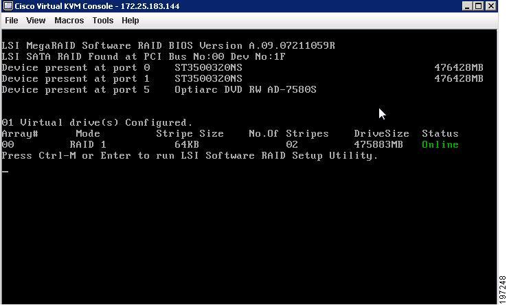
When you boot the server and quiet is disabled (see the "How to Disable Quiet Boot" section), information about the controller appears along with the prompts for the key combination to launch the LSI option ROM-based utilities for your controller.
During the verbose book process, watch for the prompt for the controller:
•
•
For More Information
The LSI utilities have help documentation for more information. For basic information on RAID and how to use the LSI utilities, see the following documentation:
•
•
•
Moving a RAID Cluster
This section describes how to set a server to recognize a RAID array created on another server. This procedure is useful when upgrading from the M1 version of a server to the M2 server. It can also be used any time you need to move data on a RAID array between servers. An array that was created on another server and not recognized on its current server is a foreign array. A native array is an active array and is recognized on the server.
For UCS Manager Release 1.4(1), follow these steps to move a RAID cluster:
Step 1
Step 2
Note
Step 3
Step 4
Step 5
Step 6
Step 7
Step 8
Step 9
Step 10
Step 11
Step 12
Step 13
Step 14
For UCS Manager Release 1.4(2) and later versions, follow these steps to move a RAID cluster:
Step 1
Step 2
Step 3
Note
Step 4
Step 5
Step 6
Step 7
If each of the preceding steps runs without issues, the servers will boot up with the OS that was installed on the respective RAID volumes prior to the RAID Cluster Migration.
Adapter Issues
A problem with the Ethernet or FCoE adapter can cause a server to fail to connect to the network and make it unreachable from Cisco UCS Manager. All adapters are unique Cisco designs and non-Cisco adapters are not supported. If adapter issues are suspected, consider the following:
•
•
•
•
•
•
•
Cisco UCS B250
All
M71KR-Q or -E + M81KR
M72KR-Q or -E + M81KRCisco UCS B440
All except 82598KR-CI
M72KR-Q or -E + M81KR
Known Issues
There are a number of known issues and open bugs with adapters. These problems are called out in the Release Notes documentation. Refer to the document for your software release. The following is a persistent known condition:
(CSCtd32884 and CSC71310) The type of the adapter in a server affects the maximum transmission unit (MTU) supported. The network MTU that is above the maximum can cause the packet to be dropped for the following adapters:
•
•
Troubleshooting Adapter Errors
The link LED on the front of the server is off if the adapter cannot establish even one network link. It is green if one or more of the links are active. Any adapter errors are reported in the LEDs on the motherboard. See the "Diagnostics Button and LEDs" section.
To use the Cisco UCS Manager GUI to determine the type of adapter errors being experienced, in the navigation pane, expand the chassis and choose the server. In the Inventory window, choose the Interface Cards tab. Any adapter errors on that server are displayed on the screen.
You can check adapter state information in the CLI by using the following commands:
UCS-A# scope server chassis-id/server-id
UCS-A /chassis/server # show adapter [detail]
Recommended Solutions
Table 6-3 contains a list of guidelines and recommended solutions that can assist you in troubleshooting adapter issues. These suggested solutions include those solutions that are described in the "Known Issues" section and the "Troubleshooting DIMM Errors" section.
Power Issues
A problem with a server's onboard power system can cause a server to shut down without warning, fail to power on, or fail the discovery process.
Known Issues
The following are known power issues:
FET Failure in a Cisco UCS B440 Server
Problem
The failure of a field effect transistor (FET) in a Cisco UCS B440 server's power section can cause the server to shut down, fail to power on, or fail the discovery process. When the server has detected the failure, you are unable to power on the server, even using the front panel power button.
To determine whether a FET failure has occurred, perform the following steps:
Step 1
Step 2
58f | 06/28/2011 22:00:19 | BMC | Power supply POWER_SYS_FLT #0xdb | Predictive Failure
deasserted | Asserted
Step 3
Fabric-Interconnect-A# connect cimc chassis/serverTrying 127.5.1.1...Connected to 127.5.1.1.Escape character is '^]'.CIMC Debug Firmware Utility Shell[ help ]# sensors faultHDD0_INFO | 0x0 | discrete | 0x2181| na | na | na | na | na | naHDD1_INFO | 0x0 | discrete | 0x2181| na | na | na | na | na | na..[lines removed for readability].LED_RTC_BATT_FLT | 0x0 | discrete | 0x2180| na | na | na | na | na | naPOWER_SYS_FLT | 0x0 | discrete | 0x0280| na | na | na | na | na | na[ sensors fault]#For the POWER_SYS_FLT sensor, a reading of 0x0280 confirms the FET failure. In normal operation, this sensor will have reading of 0x0180.
Recommended Action
If you determine that a FET failure has occurred, perform the following steps:
Step 1
•
•
Step 2
Step 3
Gathering Information Before Calling Support
If you cannot isolate the issue to a particular component, consider the following questions. They can be helpful when contacting the Cisco Technical Assistance Center (TAC).
1.
2.
3.
4.
5.
6.
When contacting Cisco TAC for any Cisco UCS issues, it is important to capture the tech-support output from Cisco UCS Manager and the chassis in question. For more information, see the "Creating a Technical Support File" section on page 3-2.
Related Documents
Check for known issues with individual server models in the Cisco UCS Blade Server Installation and Service Notes.