Table Of Contents
About Cisco Validated Design (CVD) Program
Cisco Solution for EMC VSPEX End User Computing for 500 Citrix XenDesktop 5.6 Users
1.1 Solution Components Benefits
1.1.1 Benefits of Cisco Unified Computing System
1.1.2 Benefits of Nexus Switching
1.1.3 Benefits of EMC VNX Family of Storage Controllers
1.1.4 Benefits of VMware ESXi 5.0
1.1.5 Benefits of Citrix XenDesktop and Provisioning Server
4.1 Cisco Unified Computing System (UCS)
4.1.1 Cisco Unified Computing System Components
4.1.1 Cisco Fabric Interconnects (Managed FC Variant Only)
4.1.2 Cisco UCS C220 M3 Rack-Mount Server
4.1.3 Cisco UCS Virtual Interface Card (VIC) Converged Network Adapter
4.2.1 Enhancements in Citrix XenDesktop 5.6 Feature Pack 1
4.2.3 High-Definition User Experience Technology
4.2.4 Citrix XenDesktop Hosted VM Overview
4.2.5 Citrix XenDesktop Hosted Shared Desktop Overview
4.2.6 Citrix Machine Creation Services
4.3.1 EMC VNX5300 Used in Testing
4.5 Modular Virtual Desktop Infrastructure Technical Overview
4.5.2 Understanding Desktop User Groups
4.5.3 Understanding Applications and Data
4.5.4 Project Planning and Solution Sizing Sample Questions
4.5.6 The Solution: A Unified, Pre-Tested and Validated Infrastructure
4.6 Cisco Networking Infrastructure
4.6.1 Cisco Nexus 5548UP Switch (Unmanaged FC Variant Only)
4.6.2 Cisco Nexus 2232PP Fabric Extender (Managed FC Variant Only)
5 Architecture and Design of XenDesktop 5.6 on Cisco Unified Computing System and EMC VNX Storage
5.2 Hosted VDI Design Fundamentals
5.2.2 XenDesktop 5.6 Desktop Broker
5.3 Designing a Citrix XenDesktop 5.6 Deployment
5.4 Storage Architecture Design
6.2 Cisco Unified Computing System Configuration (Managed FC Variant Only)
6.2.1 Base Cisco UCS System Configuration
6.2.2 QoS and CoS in Cisco Unified Computing System
6.2.3 System Class Configuration
6.2.4 Cisco UCS System Class Configuration
6.2.5 Steps to Enable QOS on the Cisco Unified Computing System
6.3.1 Nexus 5548UP and VNX5300 Connectivity (Unmanaged NFS Variant)
6.3.2 Cisco UCS Fabric Interconnect 6248UP and VNX5300 Connectivity (Managed FC Variant)
6.4.2 Configuring Boot from SAN Overview
6.4.3 SAN Configuration on Cisco UCS Manager
6.4.4 Configuring Boot from SAN on EMC VNX
6.4.5 SAN Configuration on Cisco UCS Manager
6.5 EMC VNX5300 Storage Configuration
6.5.1 Physical and Logical Storage Layout for Managed FC and Unmanaged NFS Variants
6.5.2 EMC Storage Configuration for VMware ESXi 5.0 Infrastructure Servers
6.5.3 EMC FAST Cache in Practice
6.6 Installing and Configuring ESXi 5.0 Update 1
6.6.1 Install VMware ESXi 5.0 Update 1
6.6.2 Install and Configure vCenter
6.6.4 ESXi 5.0 Update 1 Cluster Configuration
6.7 Installing and Configuring Citrix XenDesktop 5.6
6.7.2 Install Citrix XenDesktop, Web Interface, Citrix XenDesktop Studio, and Optional Components
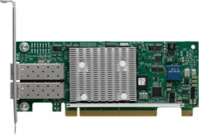
6.7.3 Configuring the License Server
6.7.4 Create SQL Database for Citrix XenDesktop
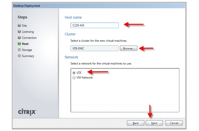
6.7.5 Configure the Citrix XenDesktop Site Hosts and Storage
6.7.6 Configure Citrix XenDesktop HDX Polices
7 Desktop Delivery Infrastructure and Golden Image Creation
7.1 Overview of Solution Components
7.2 File Servers for User Profile Management and Login VSI Share
7.3 Microsoft Windows 7 Golden Image Creation
7.3.1 Create Base Windows 7 SP1 32bit Virtual Machine
7.3.2 Add Citrix XenDesktop 5.6 Virtual Desktop Agent
7.3.3 Add Login VSI Target Software (Login VSI Test Environments Only)
7.3.4 Citrix XenDesktop Optimizations
7.3.5 Perform additional PVS and XenDesktop Optimizations
7.4 Virtual Machine Creation Using Citrix XenDesktop Machine Creation Services
8 Test Setup and Configurations
8.1 Cisco UCS Test Configuration for Single Server Scalability
8.2 Cisco UCS Configuration for Five Server Test
8.3 Testing Methodology and Success Criteria
8.3.2 User Workload SimulationLoginVSI From Login Consultants
9.1 Cisco UCS Test Configuration for Single-Server Scalability Test Results
9.2 Cisco UCS Test Configuration for 600 Desktop Scalability Test Results
9.3 Cisco UCS Test Configuration for 500 Desktop Scalability Test Results
10 Scalability Considerations and Guidelines
10.1 Cisco UCS System Configuration
10.2 Citrix XenDesktop 5.6 Hosted VDI
10.3 EMC VNX Storage Guidelines for XenDesktop Virtual Machines
10.4 VMware ESXi 5 Guidelines for Virtual Desktop Infrastructure
11.1 Cisco Reference Documents
11.2 Citrix Reference Documents
11.4 VMware Reference Documents
Appendix A—Nexus 5548 Configuration (NFS Variant Only)
Appendix B—Server Performance Metrics for 500 Users on 4 Cisco UCS C220 M3 Servers
Cisco Solution for EMC VSPEX End User Computing for 500 Citrix XenDesktop 5.6 UsersEnabled by Cisco Unified Computing System C220 M3 Servers, Cisco Nexus Switching, VMware vSphere 5, and Direct Attached EMC VNX5300
Building Architectures to Solve Business Problems
About the Authors
Mike Brennan, Sr. Technical Marketing Engineer, VDI Performance and Solutions Team Lead, Cisco Systems
Mike Brennan is a Cisco Unified Computing System architect, focusing on Virtual Desktop Infrastructure solutions with extensive experience with EMC VNX, VMware ESX/ESXi, and VMware View. He has expert product knowledge in application and desktop virtualization across all three major hypervisor platforms, both major desktop brokers, Microsoft Windows Active Directory, User Profile Management, DNS, DHCP and Cisco networking technologies.
.
About Cisco Validated Design (CVD) Program
The CVD program consists of systems and solutions designed, tested, and documented to facilitate faster, more reliable, and more predictable customer deployments. For more information visit www.cisco.com/go/designzone.
ALL DESIGNS, SPECIFICATIONS, STATEMENTS, INFORMATION, AND RECOMMENDATIONS (COLLECTIVELY, "DESIGNS") IN THIS MANUAL ARE PRESENTED "AS IS," WITH ALL FAULTS. CISCO AND ITS SUPPLIERS DISCLAIM ALL WARRANTIES, INCLUDING, WITHOUT LIMITATION, THE WARRANTY OF MERCHANTABILITY, FITNESS FOR A PARTICULAR PURPOSE AND NONINFRINGEMENT OR ARISING FROM A COURSE OF DEALING, USAGE, OR TRADE PRACTICE. IN NO EVENT SHALL CISCO OR ITS SUPPLIERS BE LIABLE FOR ANY INDIRECT, SPECIAL, CONSEQUENTIAL, OR INCIDENTAL DAMAGES, INCLUDING, WITHOUT LIMITATION, LOST PROFITS OR LOSS OR DAMAGE TO DATA ARISING OUT OF THE USE OR INABILITY TO USE THE DESIGNS, EVEN IF CISCO OR ITS SUPPLIERS HAVE BEEN ADVISED OF THE POSSIBILITY OF SUCH DAMAGES.
THE DESIGNS ARE SUBJECT TO CHANGE WITHOUT NOTICE. USERS ARE SOLELY RESPONSIBLE FOR THEIR APPLICATION OF THE DESIGNS. THE DESIGNS DO NOT CONSTITUTE THE TECHNICAL OR OTHER PROFESSIONAL ADVICE OF CISCO, ITS SUPPLIERS OR PARTNERS. USERS SHOULD CONSULT THEIR OWN TECHNICAL ADVISORS BEFORE IMPLEMENTING THE DESIGNS. RESULTS MAY VARY DEPENDING ON FACTORS NOT TESTED BY CISCO.
CCDE, CCENT, Cisco Eos, Cisco Lumin, Cisco Nexus, Cisco StadiumVision, Cisco TelePresence, Cisco WebEx, the Cisco logo, DCE, and Welcome to the Human Network are trademarks; Changing the Way We Work, Live, Play, and Learn and Cisco Store are service marks; and Access Registrar, Aironet, AsyncOS, Bringing the Meeting To You, Catalyst, CCDA, CCDP, CCIE, CCIP, CCNA, CCNP, CCSP, CCVP, Cisco, the Cisco Certified Internetwork Expert logo, Cisco IOS, Cisco Press, Cisco Systems, Cisco Systems Capital, the Cisco Systems logo, Cisco Unity, Collaboration Without Limitation, EtherFast, EtherSwitch, Event Center, Fast Step, Follow Me Browsing, FormShare, GigaDrive, HomeLink, Internet Quotient, IOS, iPhone, iQuick Study, IronPort, the IronPort logo, LightStream, Linksys, MediaTone, MeetingPlace, MeetingPlace Chime Sound, MGX, Networkers, Networking Academy, Network Registrar, PCNow, PIX, PowerPanels, ProConnect, ScriptShare, SenderBase, SMARTnet, Spectrum Expert, StackWise, The Fastest Way to Increase Your Internet Quotient, TransPath, WebEx, and the WebEx logo are registered trademarks of Cisco Systems, Inc. and/or its affiliates in the United States and certain other countries.
All other trademarks mentioned in this document or website are the property of their respective owners. The use of the word partner does not imply a partnership relationship between Cisco and any other company. (0809R)
© 2013 Cisco Systems, Inc. All rights reserved
Cisco Solution for EMC VSPEX End User Computing for 500 Citrix XenDesktop 5.6 Users
1 Overview
Industry trends indicate a vast data center transformation toward shared infrastructures. Enterprise customers are moving away from silos of information and toward shared infrastructures, to virtualized environments, and eventually to the cloud to increase agility, improve availability and reduce costs.
Five Cisco UCS C220 M3 Rack Servers were utilized in the design to provide N+1 fault tolerance for 500 Virtual Windows 7 desktops at the server level, guaranteeing the same end-user experience if just 4 C220 M3 servers are operational. In fact, the five server architecture can comfortably support 600 desktops with N+1 server fault tolerance. For that reason, the document architecture will refer to supporting a 600 desktop capacity with five Cisco UCS C220 M3 servers.
Alternatively, with just four Cisco UCS C220 M3 Rack Servers, we can effectively host 500 users with all servers online or 450 Users with 3 UCS C220 M3 servers running.
This study was performed in conjunction with EMC's VSPEX program and aligns closely with the Cisco Solution for EMC VSPEX C500 Reference Architecture and Deployment Guide.
1.1 Solution Components Benefits
Each of the components of the overall solution materially contributes to the value of functional design contained in this document.
1.1.1 Benefits of Cisco Unified Computing System
Cisco Unified Computing System™ is the first converged data center platform that combines industry-standard, x86-architecture servers with networking and storage access into a single converged system. The system is entirely programmable using unified, model-based management to simplify and speed deployment of enterprise-class applications and services running in bare-metal, virtualized, and cloud computing environments.
Benefits of the Unified Computing System include:
Architectural flexibility
•
Cisco UCS B-Series blade servers for infrastructure and virtual workload hosting
•
•
•
Infrastructure Simplicity
•
•
•
•
Business Agility
•
•
•
•
1.1.2 Benefits of Nexus Switching
1.1.2.1 Cisco Nexus 5548 (NFS Variant)
The Cisco Nexus 5548UP Switch, used exclusively in the NFS variant or the EMC VSPEX C500 architecture, delivers innovative architectural flexibility, infrastructure simplicity, and business agility, with support for networking standards. For traditional, virtualized, unified, and high-performance computing (HPC) environments, it offers a long list of IT and business advantages, including:
Architectural Flexibility
•
•
•
•
•
•
•
Infrastructure Simplicity
•
•
•
•
•
Business Agility
•
•
•
Specifications At-a-Glance
•
•
•
•
1.1.2.2 Cisco Nexus 2232PP Fabric Extender (Fibre Channel Variant)
The Cisco Nexus 2232PP 10GE Fabric Extender provides 32 10 Gb Ethernet and Fibre Channel Over Ethernet (FCoE) Small Form-Factor Pluggable Plus (SFP+) server ports and eight 10 Gb Ethernet and FCoE SFP+ uplink ports in a compact 1 rack unit (1RU) form factor.
The Nexus 2232PP in conjunction with VIC1225 converged network adapters in the Cisco UCS C220 M3 rack servers provide fault-tolerant single wire management of the rack servers through up to 8 uplink ports to Cisco Fabric Interconnects.
Reduce TCO
•
•
•
•
Cisco Nexus 2232PPs were utilized in the FC variant of the study only.
1.1.3 Benefits of EMC VNX Family of Storage Controllers
The EMC VNX Family delivers industry leading innovation and enterprise capabilities for file, block, and object storage in a scalable, easy-to-use solution. This next-generation storage platform combines powerful and flexible hardware with advanced efficiency, management, and protection software to meet the demanding needs of today's enterprises.
All of this is available in a choice of systems ranging from affordable entry-level solutions to high performance, petabyte-capacity configurations servicing the most demanding application requirements. The VNX family includes the VNXe Series, purpose-built for the IT generalist in smaller environments , and the VNX Series , designed to meet the high-performance, high scalability, requirements of midsize and large enterprises.
VNX Series - Simple, Efficient, Powerful
A robust platform for consolidation of legacy block storage, file-servers, and direct-attached application storage, the VNX series enables organizations to dynamically grow, share, and cost-effectively manage multi-protocol file systems and multi-protocol block storage access. The VNX Operating environment enables Microsoft Windows and Linux/UNIX clients to share files in multi-protocol (NFS and CIFS) environments. At the same time it supports iSCSI, Fiber Channel, and FCoE access for high bandwidth and latency-sensitive block applications. The combination of EMC Atmos Virtual Edition software and VNX storage supports object-based storage and enables customers to manage web applications from EMC Unisphere. The VNX series next generation storage platform is powered by Intel quad-core Xeon 5600 series with a 6 -Gb/s SAS drive back-end and delivers demonstrable performance improvements over the previous generation mid-tier storage:
•
•
•
1.1.4 Benefits of VMware ESXi 5.0
As virtualization is now a critical component to an overall IT strategy, it is important to choose the right vendor. VMware is the leading business virtualization infrastructure provider, offering the most trusted and reliable platform for building private clouds and federating to public clouds.
Find out how only VMware delivers on the core requirements for a business virtualization infrastructure solution.
And best of all, VMware delivers while providing
1.1.5 Benefits of Citrix XenDesktop and Provisioning Server
XenDesktop is a comprehensive desktop virtualization solution that includes all the capabilities required to deliver desktops, apps and data securely to every user in an enterprise. Trusted by the world's largest organizations, XenDesktop has won numerous awards for its leading-edge technology and strategic approach to desktop virtualization.
XenDesktop helps businesses:
•
•
•
•
A complete line of XenDesktop editions lets you choose the ideal solution for your business needs and IT strategy. XenDesktop VDI edition, a scalable solution for delivering virtual desktops in a VDI scenario, includes Citrix HDX technology, provisioning services, and profile management. XenDesktop Enterprise edition is an enterprise-class desktop virtualization solution with FlexCast delivery technology that delivers the right type of virtual desktop with on-demand applications to any user, anywhere. The comprehensive Platinum edition includes advanced management, monitoring and security capabilities.
1.2 Audience
This document describes the architecture and deployment procedures of an infrastructure comprised of Cisco, EMC, VMware and Citrix virtualization. The intended audience of this document includes, but is not limited to, sales engineers, field consultants, professional services, IT managers, partner engineering, and customers who want to deploy the solution described in this document.
2 Summary of Main Findings
The combination of technologies from Cisco Systems, Inc, Citrix Systems, Inc, VMware and EMC produced a highly efficient, robust and scalable Virtual Desktop Infrastructure (VDI) for a hosted virtual desktop deployment. Key components of the solution included:
•
•
•
•
•
•
•
•
•
•
•
•
•
•
•
3 Architecture
3.1 Hardware Deployed
The architecture deployed is highly modular. While each customer's environment might vary in its exact configuration, once the reference architecture contained in this document is built, it can easily be scaled as requirements and demands change. This includes scaling both up (adding additional resources within a UCS Domain) and out (adding additional Cisco UCS Domains and VNX Storage arrays).
The 500 User XenDesktop 5.6 solution with N+1 fault tolerance for 450 users, includes Cisco networking, four Cisco UCS C220 M3 Rack-Mount Servers and an EMC VNX5300 storage system.
The 600 User XenDesktop 5.6 solution with N+1 fault tolerance for 600 users, includes Cisco networking, five Cisco UCS C220 M3 Rack-Mount Servers and the same EMC VNX5300 storage system. The study will illustrate this configuration of the solution.
The same VNX5300 configuration is used with the 500 and 600 user examples.
Two variants to the design are offered:
•
•
This document details the deployment of Citrix XenDesktop 5.6 with Machine Creation Service on VMware ESXi 5.0 Update 1
Figure 1 Citrix XenDesktop 5.6 600 User Hardware Components- Managed C220 M3 Rack-Mount Servers 8 Gb Fibre Channel Storage to Cisco UCS Connectivity

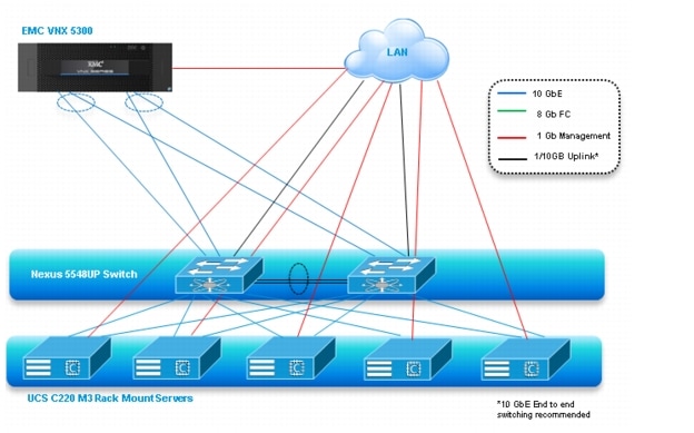
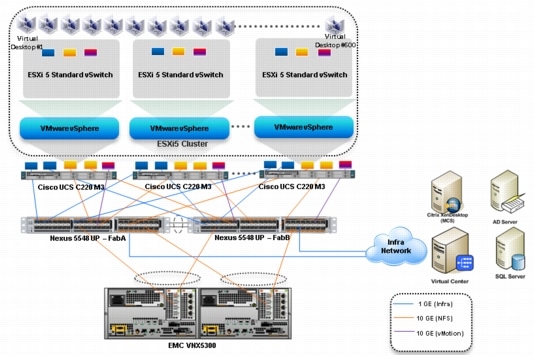
Figure 2 Citrix XenDesktop 5.6 600 User Hardware Components- Unmanaged C220 M3 Rack-Mount Servers 10 Gb Ethernet NFS Storage to Cisco UCS Connectivity
The reference configuration includes:
•
•
•
•
•
•
The EMC VNX5300 disk shelf, disk and Fast Cache configurations are detailed in Section 5.4 Storage Architecture Design later in this document.
3.2 Software Revisions
Table 1 Software Used in this Deployment
3.3 Configuration Guidelines
The 500-600 User XenDesktop 5.6 solution described in this document provides details for configuring a fully redundant, highly-available configuration. Configuration guidelines are provided that refer to which redundant component is being configured with each step, whether that be A or B. For example, SP A and SP B are used to identify the two EMC VNX storage controllers that are provisioned with this document while Nexus A and Nexus B identify the pair of Cisco Nexus switches that are configured. The Cisco UCS Fabric Interconnects are configured similarly.
This document is intended to allow the reader to configure the Citrix XenDesktop 5.6 with the Machine Configuration Server customer environment as stand-alone solution.
3.3.1 VLANs
For the 500 User XenDesktop 5.6 solution, we utilized VLANs to isolate and apply access strategies to various types of network traffic. Table 2 details the VLANs used in this study.
Table 2 VLANS
3.3.2 VMware Clusters
We utilized two VMware Clusters to support the solution and testing environment in both variants:
•
•
4 Infrastructure Components
This section describes all of the infrastructure components used in the solution outlined in this study.
4.1 Cisco Unified Computing System (UCS)
Cisco Unified Computing System is a set of pre-integrated data center components that comprises blade servers, adapters, fabric interconnects, and extenders that are integrated under a common embedded management system. This approach results in far fewer system components and much better manageability, operational efficiencies, and flexibility than comparable data center platforms.
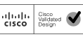
4.1.1 Cisco Unified Computing System Components
Cisco UCS components are shown in Cisco Unified Computing System Components.
Figure 3 Cisco Unified Computing System Components
The Cisco Unified Computing System is designed from the ground up to be programmable and self-integrating. A server's entire hardware stack, ranging from server firmware and settings to network profiles, is configured through model-based management. With Cisco virtual interface cards, even the number and type of I/O interfaces is programmed dynamically, making every server ready to power any workload at any time.
With model-based management, administrators manipulate a model of a desired system configuration, associate a model's service profile with hardware resources and the system configures itself to match the model. This automation speeds provisioning and workload migration with accurate and rapid scalability. The result is increased IT staff productivity, improved compliance, and reduced risk of failures due to inconsistent configurations.
Cisco Fabric Extender technology reduces the number of system components to purchase, configure, manage, and maintain by condensing three network layers into one. It eliminates both blade server and hypervisor-based switches by connecting fabric interconnect ports directly to individual blade servers and virtual machines. Virtual networks are now managed exactly as physical networks are, but with massive scalability. This represents a radical simplification over traditional systems, reducing capital and operating costs while increasing business agility, simplifying and speeding deployment, and improving performance.
Note
The components of the Cisco Unified Computing System and Nexus switches that were used in the study are discussed below
4.1.1 Cisco Fabric Interconnects (Managed FC Variant Only)
Cisco UCS Fabric Interconnects create a unified network, storage and management fabric throughout the Cisco UCS. They provide uniform access to both networks and storage, eliminating the barriers to deploying a fully virtualized environment based on a flexible, programmable pool of resources.
Cisco Fabric Interconnects comprise a family of line-rate, low-latency, lossless 10-GE, Cisco Data Center Ethernet, and FCoE interconnect switches. Based on the same switching technology as the Cisco Nexus 5000 Series, Cisco UCS 6000 Series Fabric Interconnects provide the additional features and management capabilities that make them the central nervous system of Cisco Unified Computing System.
The Cisco UCS Manager software runs inside the Cisco UCS Fabric Interconnects. The Cisco UCS 6000 Series Fabric Interconnects expand the Cisco UCS networking portfolio and offer higher capacity, higher port density, and lower power consumption. These interconnects provide the management and communication backbone for the Cisco UCS B-Series Blades and Cisco UCS Blade Server Chassis.
All chassis and all blades that are attached to the Fabric Interconnects are part of a single, highly available management domain. By supporting unified fabric, the Cisco UCS 6200 Series provides the flexibility to support LAN and SAN connectivity for all blades within its domain right at configuration time. Typically deployed in redundant pairs, the Cisco UCS Fabric Interconnect provides uniform access to both networks and storage, facilitating a fully virtualized environment.
The Cisco UCS Fabric Interconnect family is currently comprised of the Cisco 6100 Series and Cisco 6200 Series of Fabric Interconnects.
4.1.2.1 Cisco UCS 6248UP 48-Port Fabric Interconnect
The Cisco UCS 6248UP 48-Port Fabric Interconnect is a 1 RU, 10-GE, Cisco Data Center Ethernet, FCoE interconnect providing more than 1 Tbps throughput with low latency. It has 32 fixed ports of Fibre Channel, 10-GE, Cisco Data Center Ethernet, and FCoE SFP+ ports.
One expansion module slot can be up to sixteen additional ports of Fibre Channel, 10-GE, Cisco Data Center Ethernet, and FCoE SFP+. The expansion module was not required for this study.
4.1.2 Cisco UCS C220 M3 Rack-Mount Server
Cisco Unified Computing System is the first truly unified data center platform that combines industry-standard, x86-architecture blade and rack servers with networking and storage access into a single system. Key innovations in the platform include a standards-based unified network fabric, Cisco Virtualized Interface Card (VIC) support, and Cisco UCS Manager Service Profile and Direct Storage Connection support. The system uses a wire- once architecture with a self-aware, self-integrating, intelligent infrastructure that eliminates the time-consuming, manual, error-prone assembly of components into systems.
Managed Cisco UCS C-Series Rack-Mount Servers reduce total cost of ownership (TCO) and increase business agility by extending Cisco Unified Computing System™ innovations to a rack-mount form factor. These servers:
•
•
•
•
•
Note
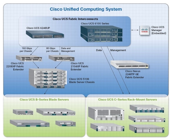
4.1.3 Cisco UCS Virtual Interface Card (VIC) Converged Network Adapter
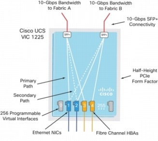
A Cisco® innovation, the Cisco UCS Virtual Interface Card (VIC) 1225 (Figure 1) is a dual-port Enhanced Small Form-Factor Pluggable (SFP+) 10 Gigabit Ethernet and Fibre Channel over Ethernet (FCoE)-capable PCI Express (PCIe) card designed exclusively for Cisco UCS C-Series Rack Servers. With its half-height design, the card preserves full-height slots in servers for third-party adapters certified by Cisco. It incorporates next-generation converged network adapter (CNA) technology from Cisco, providing investment protection for future feature releases.
4.1.3.1 Cisco UCS Virtual Interface Card 1225
The card enables a policy-based, stateless, agile server infrastructure that can present up to 256 PCIe standards-compliant interfaces to the host that can be dynamically configured as either network interface cards (NICs) or host bus adapters (HBAs). In addition, the Cisco UCS VIC 1225 supports Cisco Data Center Virtual Machine Fabric Extender (VM-FEX) technology, which extends the Cisco UCS fabric interconnect ports to virtual machines, simplifying server virtualization deployment.
Figure 4 Cisco UCS VIC M81KR Converged Network Adapter
Note
4.2 Citrix XenDesktop
Citrix XenDesktop is a desktop virtualization solution that delivers Windows desktops as an on-demand service to any user, anywhere. With FlexCast™ delivery technology, XenDesktop can quickly and securely deliver individual applications or complete desktops to the entire enterprise, whether users are task workers, knowledge workers or mobile workers. Users now have the flexibility to access their desktop on any device, anytime, with a high definition user experience. With XenDesktop, IT can manage single instances of each OS, application, and user profile and dynamically assemble them to increase business agility and greatly simplify desktop management. XenDesktop's open architecture enables customers to easily adopt desktop virtualization using any hypervisor, storage, or management infrastructure.
4.2.1 Enhancements in Citrix XenDesktop 5.6 Feature Pack 1
XenDesktop 5.6 Feature Pack 1, builds upon the themes of the last release which are about reducing cost and making it easier to do desktop virtualization. Below, is an overview of new or updated technologies and capabilities contained in Feature Pack 1:
•
•
•
•
•
•
•
4.2.2 FlexCast Technology
Citrix XenDesktop with FlexCast is an intelligent delivery technology that recognizes the user, device, and network, and delivers the correct virtual desktop and applications specifically tailored to meet the performance, security, and flexibility requirements of the user scenario. FlexCast technology delivers any type of virtual desktop to any device and can change this mix at any time. FlexCast also includes on-demand applications to deliver any type of virtual applications to any desktop, physical or virtual.
The FlexCast delivery technologies can be broken down into the following categories:
•
•
•
•
•
•
4.2.3 High-Definition User Experience Technology
Citrix High-Definition User Experience (HDX) technology is a set of capabilities that delivers a high definition desktop virtualization user experience to end users for any application, device, or network. These user experience enhancements balance performance with low bandwidth, whether it be plugging in a USB device, printing from a network printer or rendering real time video and audio. Citrix HDX technology provides network and application performance optimizations for a "like local PC" experience over LANs and a very usable experience over low bandwidth and high latency WAN connections.
4.2.4 Citrix XenDesktop Hosted VM Overview
Hosted VM uses a hypervisor to host all the desktops in the data center. Hosted VM desktops can either be pooled or assigned. Pooled virtual desktops use Citrix Provisioning Services to stream a standard desktop image to each desktop instance upon boot-up. Therefore, the desktop is always returned to its clean, original state. Citrix Provisioning Services enables the streaming of a single desktop image to create multiple virtual desktops on one or more hypervisors in a data center. This feature greatly reduces the amount of storage required compared to other methods of creating virtual desktops. The high-level components of a Citrix XenDesktop architecture utilizing the Hosted VM model for desktop delivery are shown in below Citrix XenDesktop on VMware vSphere
Figure 5 Citrix XenDesktop on VMware vSphere

Components of a Citrix XenDesktop architecture using Hosted VM include:
•
•
•
•
•
•
•
•
•
•
•
All of the aforementioned components interact to provide a virtual desktop to an end user based on the FlexCast Hosted VM desktop delivery model leveraging the Provisioning Services feature of XenDesktop. This architecture provides the end user with a pristine desktop at each logon based on a centralized desktop image that is owned and managed by IT.
4.2.5 Citrix XenDesktop Hosted Shared Desktop Overview
In a typical large enterprise environment, IT will implement a mixture of Flexcast technologies to meet various workstyle needs. Like the test in this document, hosted shared desktops can be deployed alongside hosted VM desktops.
Host shared desktops has been a proven Citrix offering over many years and is deployed in some of the largest enterprises today due to its ease of deployment, reliability and scalability. Hosted shared desktops are appropriate for environments that have a standardized set of applications that do not deviate from one user to another. All users share the same desktop interface hosted on a Windows server in the backend datacenter. Hence, the level of desktop customization is limited compared to a Hosted VM desktop model.
If VM isolation is required and the ability to allocate resources to one user over another is important, the Hosted VM desktop should be the model of choice.
4.2.6 Citrix Machine Creation Services
Citrix Machine Creation Services (MCS) is the option for desktop image delivery used in this study. It uses the hypervisor APIs (XenServer, Hyper-V, and vSphere) to create, start, stop, and delete virtual machines. If you want to create a catalog of desktops with MCS, choose from the following:
•
•
•
•
In this study, Pooled-Random desktops were created and managed by Citrix Machine Creation Services.
4.3 EMC VNX Series
The VNX series delivers uncompromising scalability and flexibility for the mid-tier while providing market-leading simplicity and efficiency to minimize total cost of ownership. Customers can benefit from VNX features such as:
•
•
•
•
•
•
–
–
•
The VNX series includes five software suites and three software packs that make it easier and simpler to attain the maximum overall benefits.
Software suites available:
•
•
•
•
•
Software packs available:
•
•
4.3.1 EMC VNX5300 Used in Testing
EMC VNX 5300 provides storage by using FC (SAN) or IP (NAS) connections for virtual desktops, and infrastructure virtual machines such as Citrix XenDesktop controllers, VMware vCenter Servers, Microsoft SQL Server databases, and other supporting services. Optionally, user profiles and home directories are redirected to CIFS network shares on the VNX5300.
4.4 VMware ESXi 5.0
VMware, Inc. provides virtualization software. VMware's enterprise software hypervisors for servers—VMware ESX, Vmware ESXi, and VSphere—are bare-metal embedded hypervisors that run directly on server hardware without requiring an additional underlying operating system.
4.4.1 VMware on ESXi 5.0 HypervisorESXi 5.0 is a "bare-metal" hypervisor, so it installs directly on top of the physical server and partitions it into multiple virtual machines that can run simultaneously, sharing the physical resources of the underlying server. VMware introduced ESXi in 2007 to deliver industry-leading performance and scalability while setting a new bar for reliability, security and hypervisor management efficiency.
Due to its ultra-thin architecture with less than 100MB of code-base disk footprint, ESXi delivers industry-leading performance and scalability plus:
•
•
•
•
4.5 Modular Virtual Desktop Infrastructure Technical Overview
4.5.1 Modular Architecture
Today's IT departments are facing a rapidly-evolving workplace environment. The workforce is becoming increasingly diverse and geographically distributed and includes offshore contractors, distributed call center operations, knowledge and task workers, partners, consultants, and executives connecting from locations around the globe at all times.
An increasingly mobile workforce wants to use a growing array of client computing and mobile devices that they can choose based on personal preference. These trends are increasing pressure on IT to ensure protection of corporate data and to prevent data leakage or loss through any combination of user, endpoint device, and desktop access scenarios (Figure 6). These challenges are compounded by desktop refresh cycles to accommodate aging PCs and bounded local storage and migration to new operating systems, specifically Microsoft Windows 7.
Figure 6 The Evolving Workplace Landscape
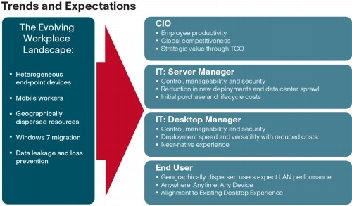
Some of the key drivers for desktop virtualization are increased data security and reduced TCO through increased control and reduced management costs.
4.5.1.1 Cisco Data Center Infrastructure for Desktop Virtualization
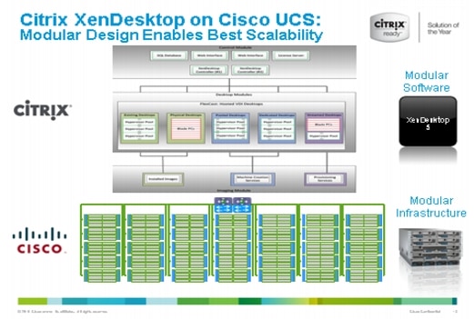
Cisco focuses on three key elements to deliver the best desktop virtualization data center infrastructure: simplification, security, and scalability. The software combined with platform modularity provides a simplified, secure, and scalable desktop virtualization platform (Figure 7).
Figure 7 Citirx XenDesktop on Cisco Unified Computing System
4.5.1.2 Simplified
Cisco UCS provides a radical new approach to industry standard computing and provides the heart of the data center infrastructure for desktop virtualization and the Cisco Virtualization Experience (VXI). Among the many features and benefits of Cisco UCS are the drastic reductions in the number of servers needed and number of cables per server and the ability to very quickly deploy or re-provision servers through Cisco UCS Service Profiles. With fewer servers and cables to manage and with streamlined server and virtual desktop provisioning, operations are significantly simplified. Thousands of desktops can be provisioned in minutes with Cisco Service Profiles and Cisco storage partners' storage-based cloning. This speeds time to productivity for end users, improves business agility, and allows IT resources to be allocated to other tasks.
IT tasks are further simplified through reduced management complexity, provided by the highly integrated Cisco UCS Manager, along with fewer servers, interfaces, and cables to manage and maintain. This is possible due to the industry-leading, highest virtual desktop density per blade of Cisco UCS along with the reduced cabling and port count due to the unified fabric and unified ports of Cisco UCS and desktop virtualization data center infrastructure.
Simplification also leads to improved and more rapid success of a desktop virtualization implementation. Cisco and its partners -Citrix (XenDesktop and Provisioning Server) and EMC - have developed integrated, validated architectures, including available pre-defined, validated infrastructure packages, known as Cisco Solutions for VSPEX.
4.5.1.3 Secure
While virtual desktops are inherently more secure than their physical world predecessors, they introduce new security considerations. Desktop virtualization significantly increases the need for virtual machine-level awareness of policy and security, especially given the dynamic and fluid nature of virtual machine mobility across an extended computing infrastructure. The ease with which new virtual desktops can proliferate magnifies the importance of a virtualization-aware network and security infrastructure. Cisco UCS and Nexus data center infrastructure for desktop virtualization provides stronger data center, network, and desktop security with comprehensive security from the desktop to the hypervisor. Security is enhanced with segmentation of virtual desktops, virtual machine-aware policies and administration, and network security across the LAN and WAN infrastructure.
4.5.1.4 Scalable
Growth of a desktop virtualization solution is all but inevitable and it is critical to have a solution that can scale predictably with that growth. The Cisco solution supports more virtual desktops per server and additional servers scale with near linear performance. Cisco data center infrastructure provides a flexible platform for growth and improves business agility. Cisco UCS Service Profiles allow for on-demand desktop provisioning, making it easy to deploy dozens or thousands of additional desktops.
Each additional Cisco UCS blad server provides near linear performance and utilizes Cisco's dense memory servers and unified fabric to avoid desktop virtualization bottlenecks. The high performance, low latency network supports high volumes of virtual desktop traffic, including high resolution video and communications.
Cisco Unified Computing System and Nexus data center infrastructure is an ideal platform for growth, with transparent scaling of server, network, and storage resources to support desktop virtualization.
4.5.1.5 Savings and Success
As demonstrated above, the simplified, secure, scalable Cisco data center infrastructure solution for desktop virtualization will save time and cost. There will be faster payback, better ROI, and lower TCO with the industry's highest virtual desktop density per server, meaning there will be fewer servers needed, reducing both capital expenditures (CapEx) and operating expenditures (OpEx). There will also be much lower network infrastructure costs, with fewer cables per server and fewer ports required, via the Cisco UCS architecture and unified fabric.
The simplified deployment of Cisco Unified Computing System for desktop virtualization speeds up time to productivity and enhances business agility. IT staff and end users are more productive more quickly and the business can react to new opportunities by simply deploying virtual desktops whenever and wherever they are needed. The high performance Cisco systems and network deliver a near-native end-user experience, allowing users to be productive anytime, anywhere.
4.5.2 Understanding Desktop User Groups
There must be a considerable effort within the enterprise to identify desktop user groups and their memberships. The most broadly recognized, high level user groups are:
•
•
•
•
•
•
There is good reason to search for and identify multiple sub-groups of the major groups listed above in the enterprise. Typically, each sub-group has different application and data requirements.
4.5.3 Understanding Applications and Data
When the desktop user groups and sub-groups have been identified, the next task is to catalog group application and data requirements. This can be one of the most time-consuming processes in the VDI planning exercise, but is essential for the VDI project's success. If the applications and data are not identified and co-located, performance will be negatively affected.
The process of analyzing the variety of application and data pairs for an organization will likely be complicated by the inclusion cloud applications, like SalesForce.com. This application and data analysis is beyond the scope of this Cisco Validated Design, but should not be omitted from the planning process. There are a variety of third party tools available to assist organizations with this crucial exercise.
4.5.4 Project Planning and Solution Sizing Sample Questions
Now that user groups, their applications and their data requirements are understood, some key project and solution sizing questions may be considered.
General project questions should be addressed at the outset, including:
•
•
•
•
•
•
Provided below is a short, non-exhaustive list of sizing questions that should be addressed for each user sub-group:
•
•
•
•
•
•
•
•
•
•
•
•
•
•
•
•
•
•
4.5.5 Cisco Services
Cisco offers assistance for customers in the analysis, planning, implementation, and support phases of the VDI lifecycle. These services are provided by the Cisco Advanced Services group. Some examples of Cisco services include:
•
•
•
4.5.6 The Solution: A Unified, Pre-Tested and Validated Infrastructure
To meet the challenges of designing and implementing a modular desktop infrastructure, Cisco, Citrix, EMC and VMware have collaborated to create the data center solution for virtual desktops outlined in this document.
Key elements of the solution include:
•
•
4.6 Cisco Networking Infrastructure
This section describes the Cisco networking infrastructure components used in the configuration.
4.6.1 Cisco Nexus 5548UP Switch (Unmanaged FC Variant Only)
Two Cisco Nexus 5548UP access switches are 1RU 10 Gigabit Ethernet, Fibre Channel, and FCoE switch offering up to 960 Gbps of throughput and up to 48 ports. The switch has 32 unified ports and one expansion slot. The Cisco Nexus 5500 platform can be equipped with an expansion module that can be used to increase the number of 10 Gigabit Ethernet and FCoE ports or to connect to Fibre Channel SANs with 8/4/2/1-Gbps Fibre Channel switch ports, or both. (Not required for this study.)
The switch has a single serial console port and a single out-of-band 10/100/1000-Mbps Ethernet management port. Two N+1 redundant, hot-pluggable power supplies and five N+1 redundant, hot-pluggable fan modules provide highly reliable front-to-back cooling.
4.6.2 Cisco Nexus 2232PP Fabric Extender (Managed FC Variant Only)
The Cisco Nexus 2232PP 10G provides 32 10 Gb Ethernet and Fibre Channel Over Ethernet (FCoE) Small Form-Factor Pluggable Plus (SFP+) server ports and eight 10 Gb Ethernet and FCoE SFP+ uplink ports in a compact 1 rack unit (1RU) form factor.
Two Nexus 2232PP 10GE Fabric Extenders were deployed to provide cluster-mode single wire management to the Cisco UCS C220 M3 rack servers.
Four of eight available 10 GbE uplinks from each Nexus 2232 were utilized to provide 40 Gb of bandwidth between the UCS 6248UP Fabric Interconnects and the Cisco UCS C220 M3 rack servers.
5 Architecture and Design of XenDesktop 5.6 on Cisco Unified Computing System and EMC VNX Storage
5.1 Design Fundamentals
There are many reasons to consider a virtual desktop solution such as an ever growing and diverse base of user devices, complexity in management of traditional desktops, security, and even Bring Your Own Computer (BYOC) to work programs. The first step in designing a virtual desktop solution is to understand the user community and the type of tasks that are required to successfully execute their role. The following user classifications are provided:
•
•
•
•
•
After the user classifications have been identified and the business requirements for each user classification have been defined, it becomes essential to evaluate the types of virtual desktops that are needed based on user requirements. There are essentially five potential desktops environments for each user:
•
•
•
•
•
For the purposes of the validation represented in this document only hosted virtual desktops were validated. Each of the sections provides some fundamental design decisions for this environment.
5.2 Hosted VDI Design Fundamentals
Citrix XenDesktop 5.6 can be used to deliver a variety of virtual desktop configurations. When evaluating a Hosted VDI deployment, consider the following:
5.2.1 Hypervisor Selection
Citrix XenDesktop is hypervisor agnostic, so any of the following three hypervisors can be used to hosted VDI-baseddesktops:
•
•
•
For this study, we utilized VMware ESXi 5.0 Update 1 and vCenter 5.0 Update 1.
5.2.2 XenDesktop 5.6 Desktop Broker
The Citrix XenDesktop 5.6 broker provides two methods of creating hosted virtual desktops:
•
•
Citrix Machine Creation Services, which is integrated directly with the XenDesktop Studio console, was used for this study.
It provides the ability to create seven types of virtual machines with random or static (assigned) users:
•
•
•
•
•
•
•
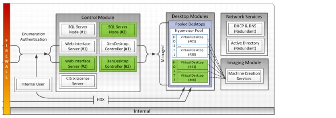
5.3 Designing a Citrix XenDesktop 5.6 Deployment
To implement our pooled desktop delivery model for this study, known as Hosted VDI Pooled Desktops, we followed the Citrix Reference Architecture for local desktop delivery.
Figure 8 Pooled Desktop Infrastructure
To read about Citrix's XenDesktop Reference Architecture - Pooled Desktops (Local and Remote) go to the following link:
http://support.citrix.com/article/CTX131049
To learn more about XenDesktop 5.6 Planning and Design go to the following link:
http://support.citrix.com/product/xd/v5.5/consulting/
5.4 Storage Architecture Design
Designing for this workload involves the deployment of many disks to handle brief periods of extreme I/O pressure, which is expensive to implement. This solution uses EMC VNX FAST Cache to reduce the number of disks required.
VNX multi-protocol support enables use of either Fibre Channel SAN-connected block storage or 10-gigabit Ethernet (GbE) connected NFS for flexible, cost effective, and easily deployable storage for VMware-based desktop virtualization.
The storage architecture use in this study was validated to support 600 hosted virtual desktops using Citrix Machine Creation Services for virtual machine provisioning and management.
Section 6.5 EMC VNX5300 Storage Configuration provides details on the storage architecture used for this solution.
6 Solution Validation
This section details the configuration and tuning that was performed on the individual components to produce a complete, validated solution.
6.1 Configuration Topology for Scalable Citrix XenDesktop 5.6 Virtual Desktop Infrastructure on Cisco Unified Computing System and EMC Storage
There are two variants of the configuration topology for this solution:
•
•
Diagrams for each variant are shown in the following sections.
Figure 9 Architecture Block Diagram-Single Wire Managed Fibre Channel Variant
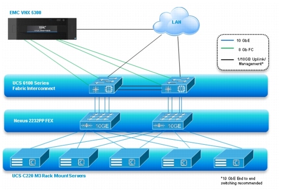
Figure 10 Architecture Block Diagram-Unmanaged NFS Variant
The figures above capture the architectural diagram for the purpose of this study. The architecture is divided into four distinct layers:
•
•
•
•
The following figure details the physical configuration of the 500-600 seat XenDesktop 5.6 environment.
Figure 11 Detailed Architecture of the Configuration for the Single Wire Managed Fibre Channel Variant
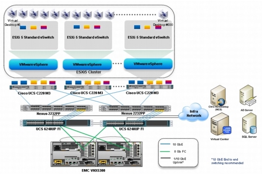
Figure 12 Detailed Architecture of the Configuration for the Unmanaged NFS Variant
Note
6.2 Cisco Unified Computing System Configuration (Managed FC Variant Only)
This section talks about the Cisco UCS configuration that was done as part of the infrastructure build out. The racking, power and installation of the chassis are described in the install guide (see http://www.cisco.com/en/US/docs/unified_computing/ucs/hw/chassis/install/ucs5108_install.html) and it is beyond the scope of this document. More details on each step can be found in the following documents:
•
•
6.2.1 Base Cisco UCS System Configuration
To configure the Cisco Unified Computing System, perform the following steps:
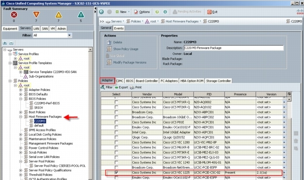
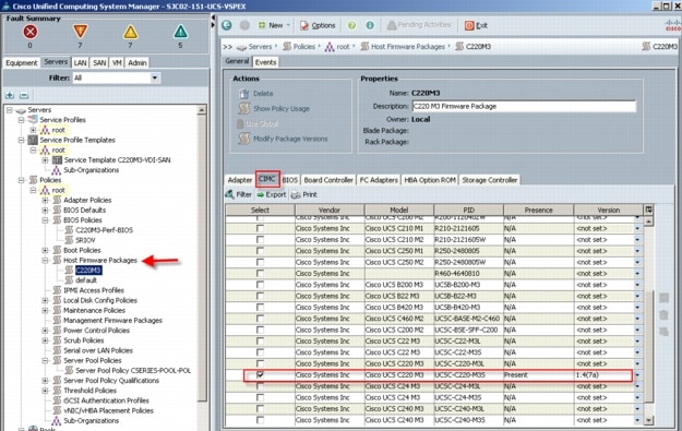
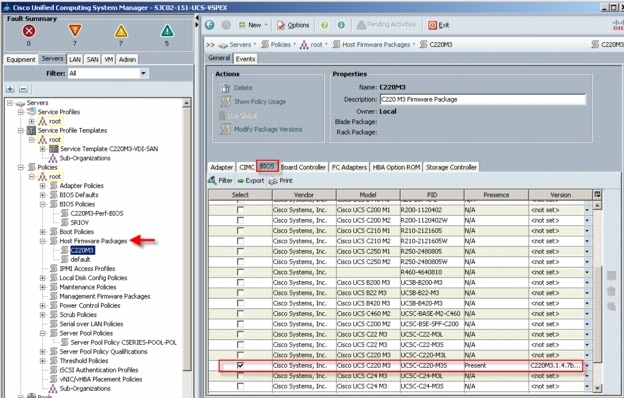
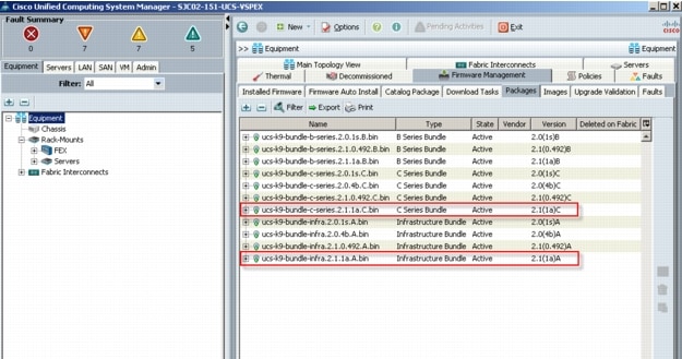 If the firmware is not current, follow the installation and upgrade guide to upgrade the Cisco UCS Manager firmware. We will use UCS Policy in Service Profiles later in this document to update all Cisco UCS components in the solution.Note: The Bios and Board Controller version numbers do not track the IO Module, Adapter, nor CIMC controller version numbers in the packages.
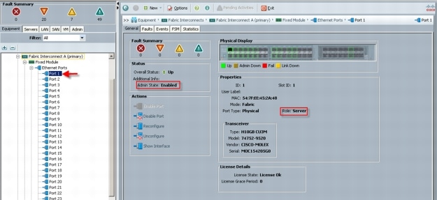
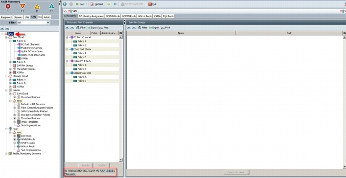
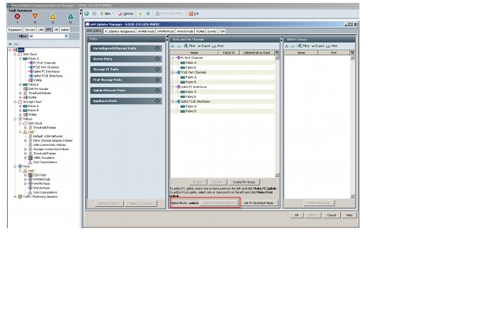
 From the Equipment tab with one of the two Fabric Interconnects highlighted in the navigation pane, use the Configure Unified Ports in the Actions panel on the General tab, to configure FC Storage ports. Note: In this example, we configured four FC Storage ports, two of which are in use. Ports to the left of the slider shown above are Ethernet ports. Ports to the right of the slider are Fibre Channel ports.
5a
Connect four uplink ports on each of the Nexus 2232PP Fabric Extenders to four server ports on one of the Cisco UCS Fabric Interconnects. (All four to one Fabric Interconnect.) Power the Nexus 2232PPs on.
7
Repeat the procedure for FEX2.
8
Download the UCS C220 M3 Rack Server Software version 1.4.(7a) or later from:
http://software.cisco.com/download/release.html?mdfid=284296253&flowid=31742&softwareid=283850974&release=1.4(7a)1&relind=null&rellifecycle=null&reltype=null&i=rb
8.1
Burn the software to a CD.
8.2
Insert the CD into each UCS C220 M3, restart the server, press F6 during the post process to view the boot menu, select the CD Rom for the boot device and update all components via the menu.
8.3
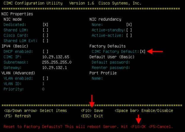
After the server firmware and CIMC have been updated, during the restart, press F8 to access the server CIMC.
8.4
Select CIMC Factory Default with spacebar, press F10, then F10 again to confirm factory defaults. This step prepares the server for management through the Nexus 2232PP FEX by Cisco UCS Manager on the Fabric Interconnects.
8.5
Connect one port of the VIC1225 from each Cisco UCS C220 M3 server to one Nexus 2232PP Fabric Extender. Connect the second VIC1225 port to the other Nexus 2232PP Fabric Extender. Repeat for all servers.
8.6
Reboot all of the Cisco UCS C220 M3 servers.
8.7
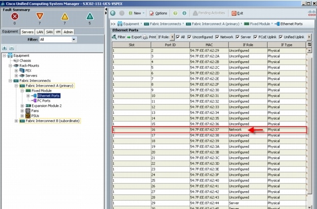
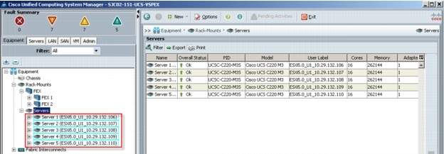
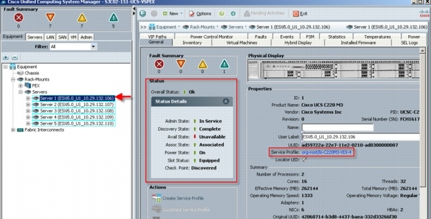
From the Equipment tab in UCS Manager, navigate to Rack-Mounts, Servers. The five UCS C220 M3 servers should be visible.
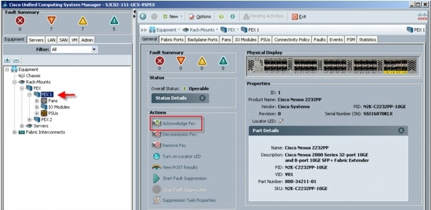
If the servers do not appear under the server node, repeat step 6, Acknowledge FEX for each FEX.
9
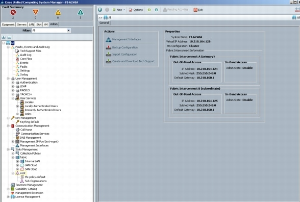
Use the Admin tab in the left pane, to configure logging, users and authentication, key management, communications, statistics, time zone and NTP services, and Licensing. Configuring your Management IP Pool (which provides IP based access to the KVM of each Cisco UCS Blade Server,) Time zone Management (including NTP time source(s)) and uploading your license files are critical steps in the process.
10
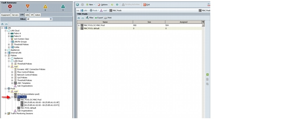
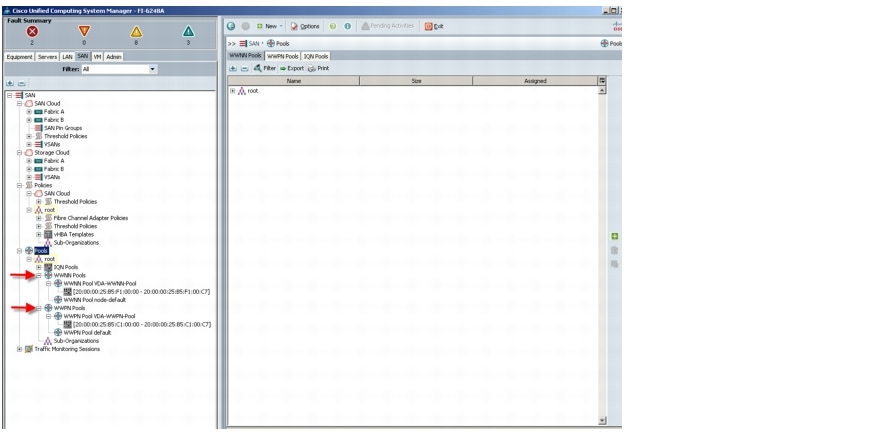
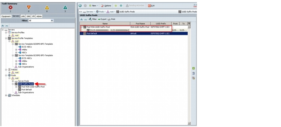
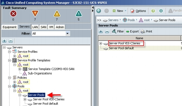
Create all the pools: MAC pool, WWPN pool, WWNN pool, UUID pool, Server pool.
11
From the LAN tab in the navigator, under the Pools node, we created a MAC address pool of sufficient size for the environment. In this project, we created a single pool with two address ranges for expandability.

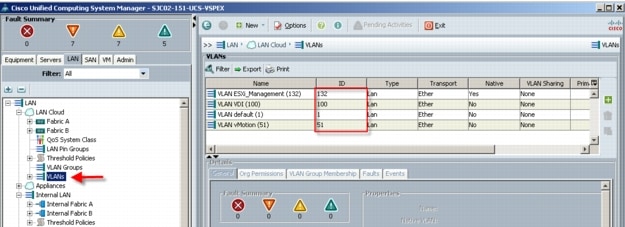 In this project we utilized three VLANs for the Managed FC variant to accommodate our three ethernet system classes. Infrastructure services shared VLAN 132.

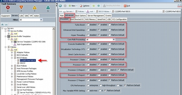
 Advanced tab, Processor settings
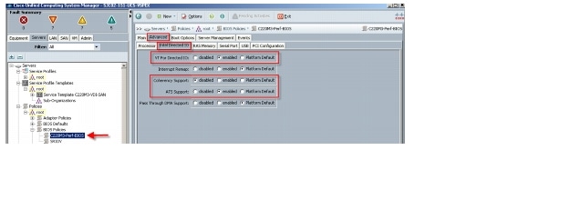
 Advanced Tab, Intel Directed IO settings
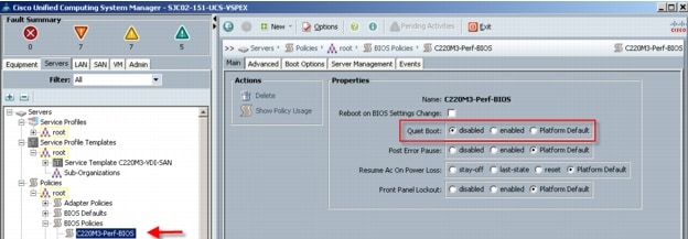
 The remaining Advanced tab settings are at platform default or not configured. Similarly, the Boot Options and Server Management tabs` settings are at defaults.Note: Be sure to Save Changes at the bottom of the page to preserve this setting. Be sure to add this policy to your blade service profile template.
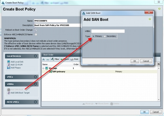 2. Add SAN boot for SAN Secondary, Click OK. Again, we left the optional vHBA name blank
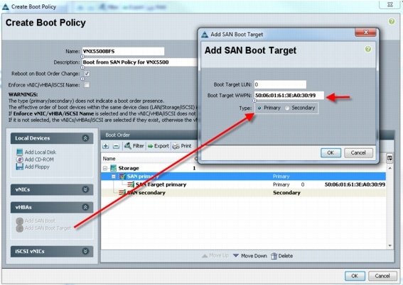
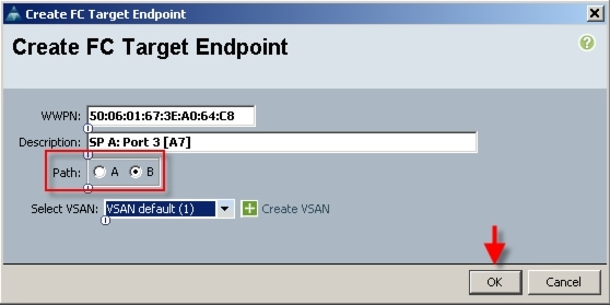
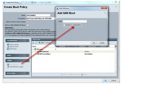 3. Now add Boot target WWPN to the SAN Primary, make sure this is exactly matches the EMC VNX pwwn. To avoid any typos, copy and paste from UCS 6248UP command as follows from each Fabric Interconnect:SJC02-151-UCS-VSPEX-A(nxos)# show fcns database vsan 10x5600ef N 50:06:01:6f:3e:a0:64:c8 (Clariion) scsi-fcp:both0x5601ef N 50:06:01:67:3e:a0:64:c8 (Clariion) scsi-fcp:bothSJC02-151-UCS-VSPEX-B(nxos)# show fcns database vsan 10xbf00ef N 50:06:01:66:3e:a0:64:c8 (Clariion) scsi-fcp:both0xbf01ef N 50:06:01:6e:3e:a0:64:c8 (Clariion) scsi-fcp:both
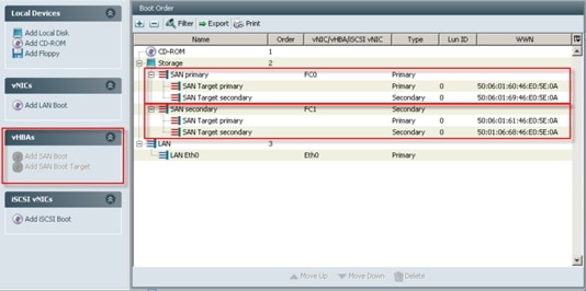
 4. Repeat step 4 for SAN primary's SAN Target Secondary5. Repeat step 4 for SAN Secondary's - SAN Target Primary6. Repeat step 4 for SAN Secondary's - SAN Target Secondary7. At the end your Boot from SAN policy should look like:
 The SAN Uplinks Manager windows will appear:
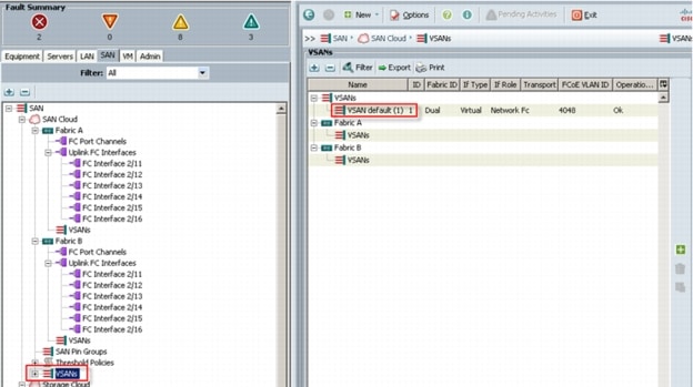
 Click the Set FC Switching Mode button.Note: Changing the FC Uplink Mode will result in both Fabric Interconnects' expansion modules immediately rebooting resulting in a 10-15 minute outage. Changing Uplink Modes should only occur during a planned maintenance window.The "Uplink Mode:" will show whether UCS is currently in "End-Host" mode or "Switching" mode. If UCS is already in "FC Switching" mode click the "Cancel" Button and proceed to the next steps. If UCS is in "End-Host" mode, click the button "Set FC Switching Mode" to change the Uplink Mode to FC Switching Mode.If you are using the default VSAN 1, from the SAN tab under the Storage Cloud node, right-click the VSAN default(1) object and choose Show Navigator. In the FC Zoning Settings area, click the FC Zoning: Enabled radio button, then click OK.Note: Use the default VSAN 1, a dual fabric VSAN, with caution. In situations where you will change the VLANs down the road, migrating from the default VSAN will cause both sides of your storage connectivity to go down simultaneously. Best practice is to configure single fabric VSANs for this reason.
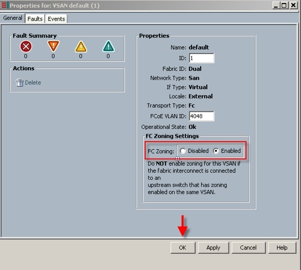 Click OK to complete the FC Zoning enablement.
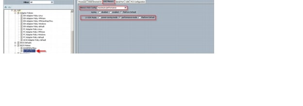
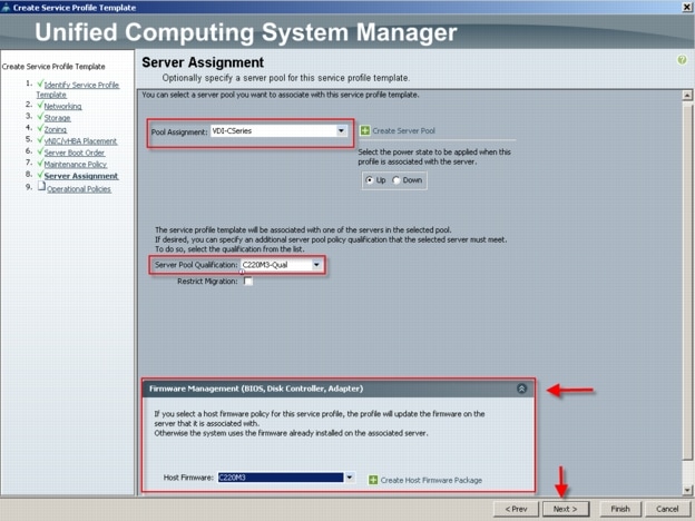
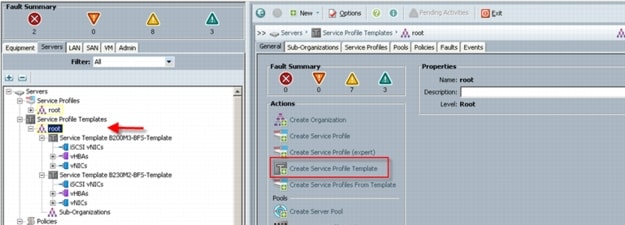 In this project, we created one template for the UCS C220 M3 Rack-Mount server model used.Follow through each section, utilizing the policies and objects you created earlier, then click Finish.Note: On the Operational Policies screen, select the appropriate performance BIOS policy you created earlier to insure maximum LV DIMM performance.Note: For automatic deployment of service profiles from your template(s), you must associate a server pool that contains servers with the template.
 On the Create vNIC page, provide a name, typically eth0, eth1, eth2, etc. Check the Use vNIC Template checkbox. Use the drop-down to select one of the vNIC templates created earlier. Use the drop-down list to choose the VMware Adapter Policy
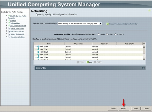
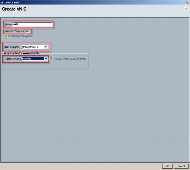 We repeat this process to create eth1, eth2, eth3 eth4 and eth5 using a different vNIC template for each vNIC. Then click Next. (Note eth5 is not shown in the graphic.)
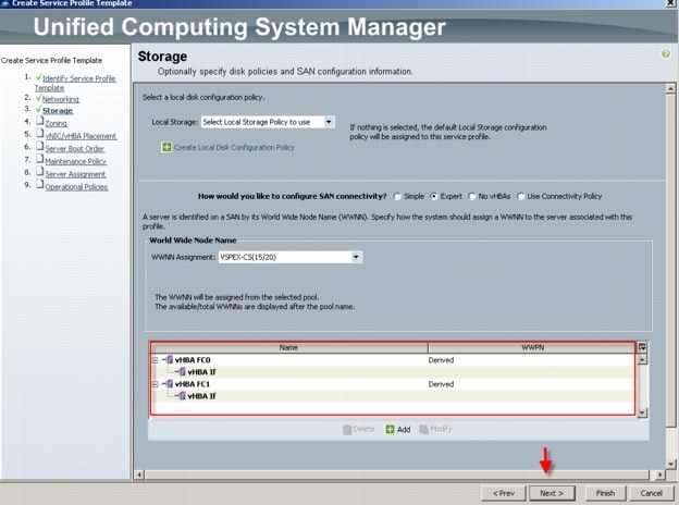
 On the Storage page, we selected the Expert mode, we selected the WWNN Pool we created earlier from the drop down list and then click Add
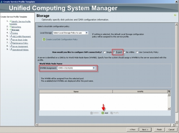 Note that we used the default Local Storage configuration in this project. Local drives on the blades were not used.
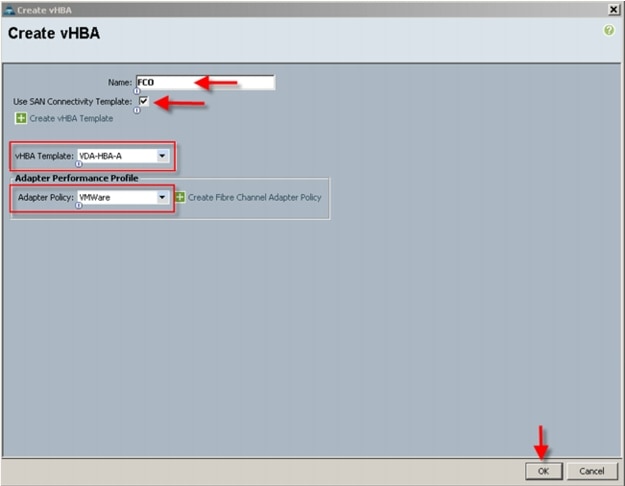 We selected the vHBA template for Fabric Interconnect A and the VMware Adapter Policy from the drop downs, then clicked OK.We repeated the process for FC1, choosing VDA-HBA-B for Fabric Interconnect B. The result is the Storage page that appears as follows:
 Click Next to continue
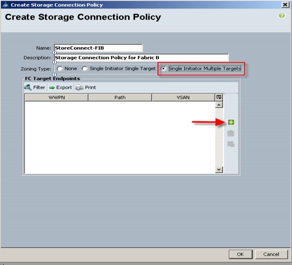
 Repeat the process to add the second port to the SAN Controller.Now click OK to add the Storage Connection Policy:
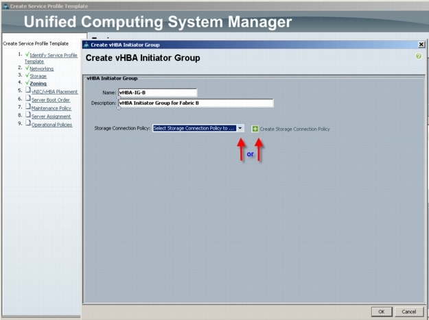
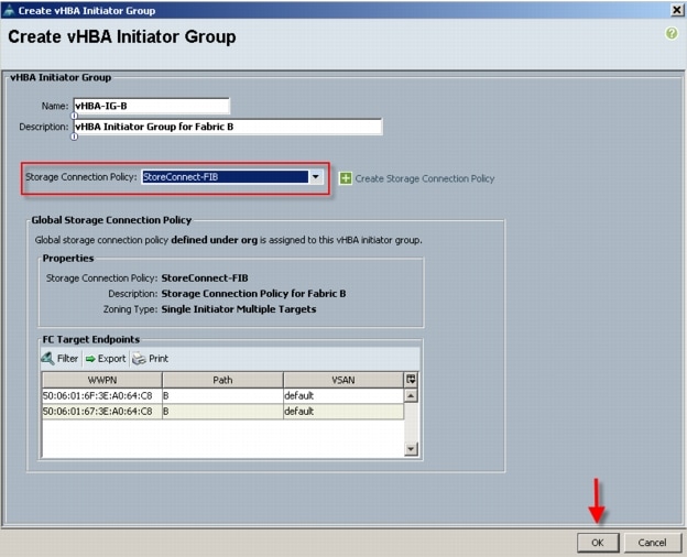
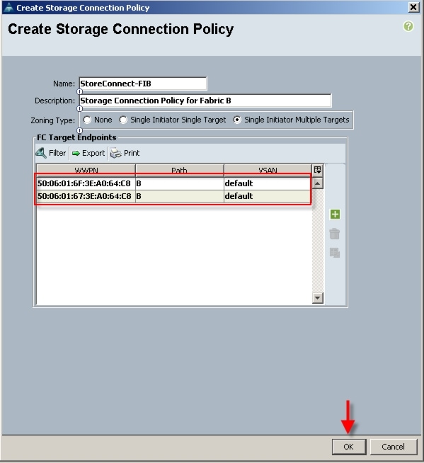 Click OK to acknowledge successful creation of the Storage Connection Policy. Repeat the process to create a Storage Connection Policy for Fabric ANow use the drop-down to add the Storage Connection Policy created above to the vHBA Initiator Group. Notice that the Connection Policy details are added to the dialogue. Click OK to create the vHBA Initiator Group.
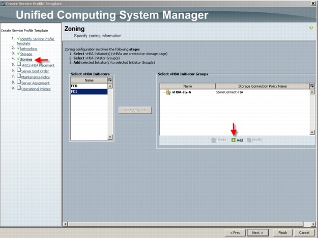
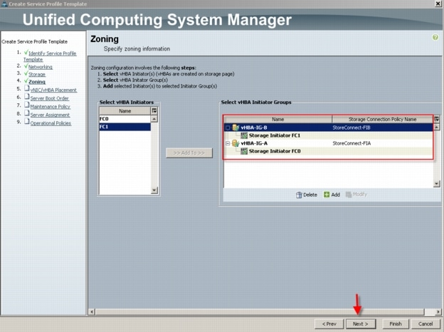
 You are returned to the Zoning page.In the Select vHBA Initiators area, click on one of the initiators, then in the Select vHBA Initiator Groups area, click on the group that is corresponds to the vHBA initiator. In our case, we are connecting FC0, which is configured for Fabric A to the vHBA-IG-A which is also configured for Fabric A. Click the Add To control between the lists to complete the association.Repeat the process for FC1 and vHBA-IG-B. Your configuration should look similar to the following:
 Click Next to continue.You can use the vNIC/vHBA Placement step to set the placement order of the ethernet and fiber channel adapters for the template. Note that you can create a policy to set the placement order which is useful if you are creating multiple profiles.
 We accepted the default placement and clicked Next.
 Click Next to continue
 Click Next to continue
 Click Next to continue.
 Click Finish to complete the wizard.Click OK to acknowledge successful creation.
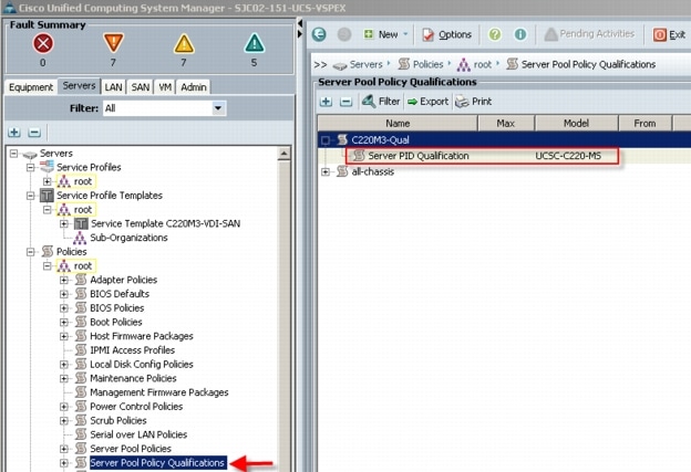
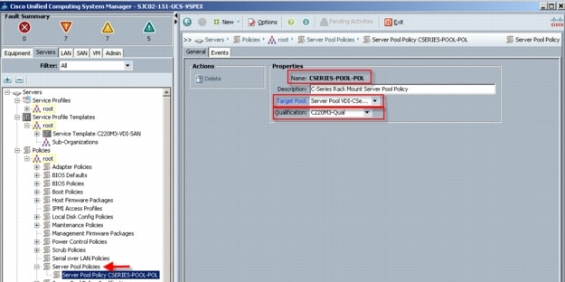
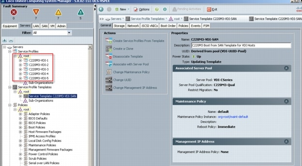 Each of the Cisco UCS C220 M3 servers was automatically assigned one of the service profiles based on its pool and pool qualification policy.
 At this point, the Cisco UCS Blade Servers are ready for hypervisor installation.
6.2.2 QoS and CoS in Cisco Unified Computing System
Cisco Unified Computing System provides different system class of service to implement quality of service including:
•
•
•
Applications like the Cisco Unified Computing System and other time sensitive applications have to adhere to a strict QOS for optimal performance.
6.2.3 System Class Configuration
Systems Class is the global operation where entire system interfaces are with defined QoS rules.
•
•
–
•
–
–
–
–
•
•
•
•
(Weight of the given priority * 100)–
Sum of weights of all priority6.2.4 Cisco UCS System Class Configuration
Cisco Unified Computing System defines user class names as follows.
•
•
•
•
Table 3 Name Table Map between Cisco Unified Computing System and the NXOS
Table 4 Class to CoS Map by default in Cisco Unified Computing System
Table 5 Default Weight in Cisco Unified Computing System
6.2.5 Steps to Enable QOS on the Cisco Unified Computing System
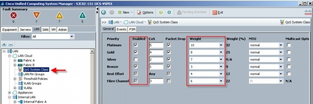
For this study, we utilized four Cisco UCS QoS System Classes to priorities four types of traffic in the infrastructure:
Table 6 QoS Priority to vNIC and VLAN Mapping
Configure Platinum, Gold, and Bronze System Classes by checking the enabled box.
Figure 13 Cisco UCS QoS System Class Configuration
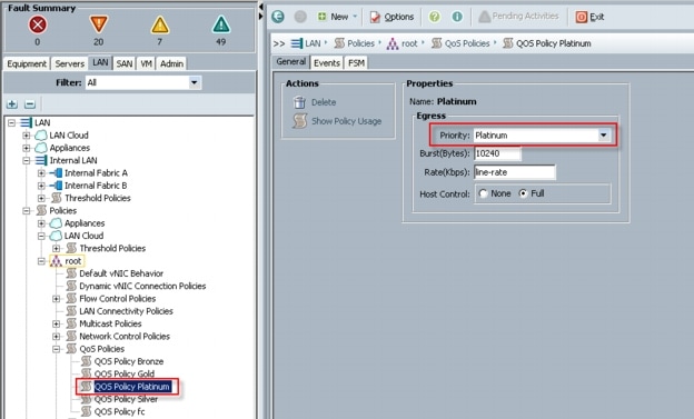
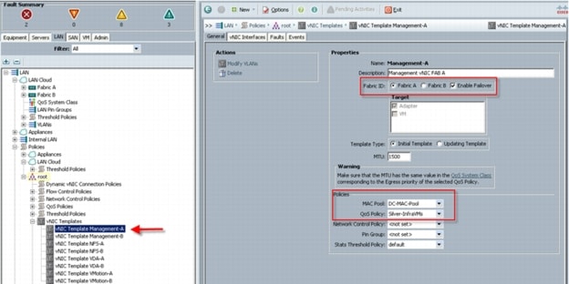
Next, in the LAN tab under Policies, Root, QoS Polices, verify QoS Policies Platinum, Gold, Silver and Bronze exist, with each QoS policy mapped to its corresponding Priority.
Figure 14 Cisco UCS QoS Policy Configuration
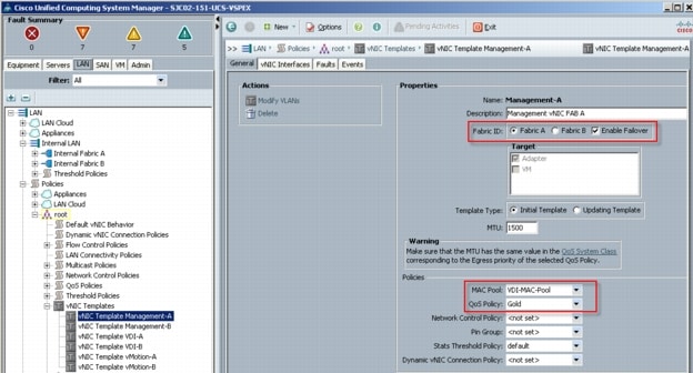
Finally, include the corresponding QoS Policy into each vNIC template using the QoS policy drop down, using the QoS Priority to vNIC and VLAN Mapping table above.
Figure 15 Utilize QoS Policy in vNIC Template
This is a unique value proposition for Cisco UCS with respect to end-to-end QOS.
6.3 LAN Configuration
The access layer LAN configuration consists of a pair of Cisco Nexus 5548s (N5Ks,) a family member of our low-latency, line-rate, 10 Gigabit Ethernet and FCoE switches for our VDI deployment.
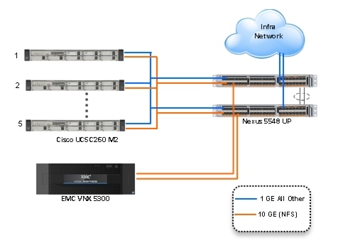
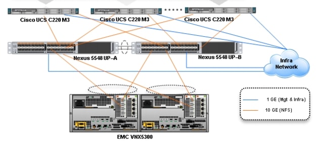
6.3.1 Nexus 5548UP and VNX5300 Connectivity (Unmanaged NFS Variant)
The access layer LAN configuration consists of a pair of Cisco Nexus 5548UPs (N5Ks,) a family member of our low-latency, line-rate, 10 Gigabit Ethernet and FCoE switches for our VDI deployment uplinked to the Customers existing L3 network.
In the Unmanaged NFS Variant, the Cisco UCS C220 M3 servers are managed in standalone mode, requiring a management/infrastructure network connection and a separate high speed data connection to the EMC VNX5300 storage system.
Five UCS C220 M3 Rack-Mount servers are connected via their VIC1225 to 10Gb ports on a pair of N5Ks to the EMC VNX NFS storage. One or both of each servers' integrated 1 Gb ethernet ports is/are connected to the upstream or top of rack L3 switch for management and all infrastructure communications.
Note
Figure 16 Unmanaged NFS Variant Ethernet Network Configuration with Cisco Nexus 5500 Series Switches
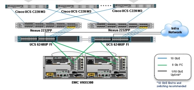
6.3.2 Cisco UCS Fabric Interconnect 6248UP and VNX5300 Connectivity (Managed FC Variant)
In the Managed FC Variant, the UCS C220 M3 servers are connected to a pair of UCS 6248UP Fabric Interconnects (FIs) via two Nexus 2232PP Fabric Extenders. The VNX5300 is connected to the FI FC Storage Ports directly via Fiber Channel. Fibre Channel zoning is done on the FIs. The FIs are uplinked to the Customer top of rack L3 switch.
In this configuration, called Managed Single Wire Cluster Setup, only the two 10 GbE ports on the VIC1225 CNA are used for all communications. In addition, Cisco UCS Manager 2.1 manages the configuration of the servers through Cisco UCS Service Profiles.
Figure 17 Managed FC Variant Network Configuration
6.4 SAN Configuration
For the two variants of this study, different equipment was used to connect to the VNX5300 storage outlined in Section 6.3 above. Only the Managed FC Variant supports booting from the VNX5300. This section describes the SAN Configuration supporting boot from SAN.
6.4.1 Boot from SAN Benefits
Booting from SAN is another key feature which helps in moving towards stateless computing in which there is no static binding between a physical server and the OS / applications it is tasked to run. The OS is installed on a SAN LUN and boot from SAN policy is applied to the service profile template or the service profile. If the service profile were to be moved to another server, the pwwn of the HBAs and the Boot from SAN (BFS) policy also moves along with it. The new server now takes the same exact character of the old server, providing the true unique stateless nature of the Cisco UCS Blade Server.
The key benefits of booting from the network:
•
•
•
•
•
•
With Boot from SAN, the image resides on a SAN LUN and the server communicates with the SAN through a host bus adapter (HBA). The HBAs BIOS contain the instructions that enable the server to find the boot disk. All FC-capable Converged Network Adapter (CNA) cards supported on Cisco UCS B-series blade servers support Boot from SAN.
After power on self-test (POST), the server hardware component fetches the boot device that is designated as the boot device in the hardware BOIS settings. Once the hardware detects the boot device, it follows the regular boot process.
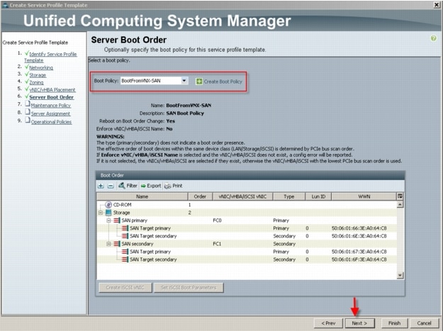
6.4.2 Configuring Boot from SAN Overview
There are three distinct phases during the configuration of Boot from SAN. The high level procedures are:
1. SAN zone configuration on the Nexus 5548UPs
2. Storage array host initiator configuration
3. Cisco UCS configuration of Boot from SAN policy in the service profile.
In each of the following sections, each high level phase will be discussed.
6.4.3 SAN Configuration on Cisco UCS Manager
The Cisco UCS Local Zoning feature requires that the UCS Fabric Interconnects be configured in FC Switching Mode rather than the default of FC End Host Mode. Once that task is completed, the properties of the VSAN used in the deployment must have the FC Zoning Setting set to Enabled.
These tasks are outlined in Section 6.2.1 Base UCS System Configuration above in step 15.
When enabled, the UCS Manager Service Profile Template creation wizard will provide the steps necessary to complete the Fibre Channel Zoning for the project.
These tasks are outlined in Section 6.2.1 Base UCS System Configuration above in step 16.
It is possible to perform FC zoning on the Fabric Interconnects from the command line. Using that method is not covered in this paper. Please refer to the Cisco UCS Manager CLI Command Reference, Release 2.1 that can be found at:
http://www.cisco.com/en/US/partner/docs/unified_computing/ucs/sw/cli/command/reference/2.1/b_command_reference_2.1_chapter_0100.html
6.4.4 Configuring Boot from SAN on EMC VNX
The steps required to configure boot from SAN LUNs on EMC VNX are as follows:
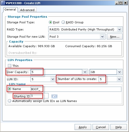
1. Create a storage pool from which LUNs will be provisioned. RAID type, drive number and type are specified in the dialogue box below. Three 600GB SAS drives are used in this example to create a RAID 5 pool. Uncheck "Schedule Auto-Tiering" to disable automatic tiering.
 2. Provision LUNs from the storage pool created in step 1. Each LUN is 12GB in size to store the ESXi hypervisor OS.
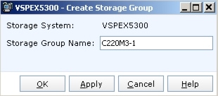
 3. Create a storage group, the container used for host to LUN mapping, for each of the ESXi hosts.
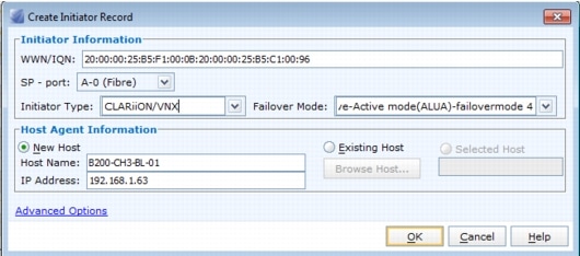
 4. Register host initiators with the storage array to associate a set of initiators with a given host. The registered host will be mapped to a specific boot LUN in the following step.
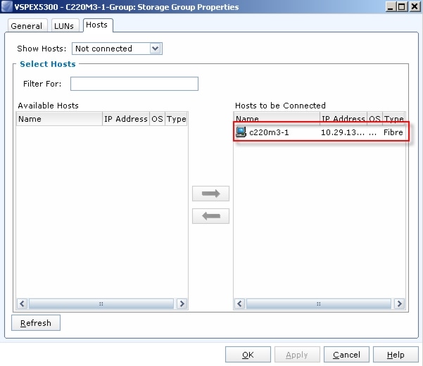
 5. Assign each registered host to a separate storage group as shown below.
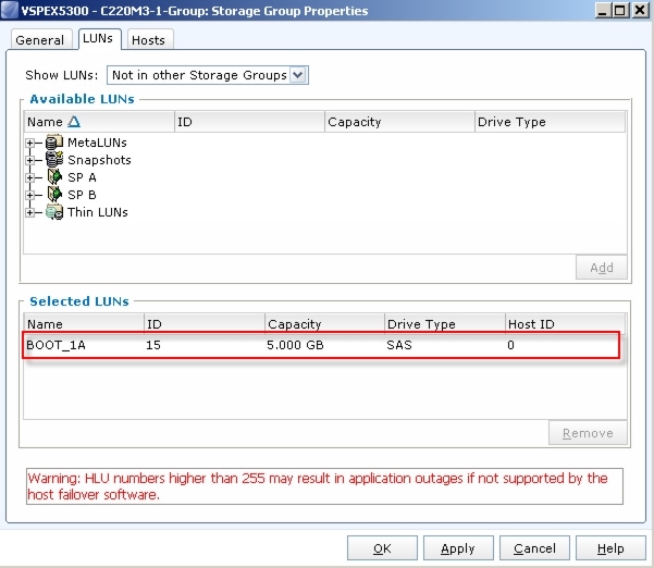
 6. Assign a boot LUN to each of the storage groups. A host LUN ID is chosen to make visible to the host. It does not need to match the array LUN ID. All boot LUNs created for the testing are assigned host LUN ID 0.
When the Cisco UCS Blade Server boots up, its vHBAs will connect to the provisioned EMC Boot LUNs and the hypervisor operating system can be installed.
6.4.5 SAN Configuration on Cisco UCS Manager
The configuration of the Boot from SAN policy in UCS Manager is covered in Section 6.2.1 Base Cisco UCS System Configuration above in step 13.
The policy created is incorporate in the Service Profile Template in Section 6.2.1 Base Cisco UCS System Configuration above in step 16o.
6.5 EMC VNX5300 Storage Configuration
The Managed FC Variant and Unmanaged NFS Variant have the same configuration to the pool level on the VNX5300. The configuration varies from there as described below.
6.5.1 Physical and Logical Storage Layout for Managed FC and Unmanaged NFS Variants
The figure below shows the physical storage layout of the disks in the reference architecture. This configuration accommodates up to 600 virtual desktops.
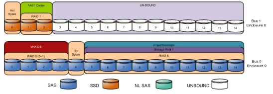
The above storage layout is used for the following configurations:
Managed Fibre Channel Variant
•
•
•
•
•
•
Note
Unmanaged NFS Variant
•
•
•
•
•
•
•
Note

•
•
Note
6.5.2 EMC Storage Configuration for VMware ESXi 5.0 Infrastructure Servers
If storage required for infrastructure virtual machines (that is, SQL server, domain controller, vCenter server, and/or XenDesktop controllers) does not exist in the production environment already and the optional user data disk pack has been purchased, configure a NFS file system or one or more FC LUNS on VNX to be used as a NFS datastore or VMFS datastore in which the infrastructure virtual machines reside.
In this study we used 5 600GB SAS drives for the Infrastructure Pool in a RAID 5 array to provision 2 500GB VMFS LUNS for our infrastructure virtual machines and files. Fast Cache was disabled on the Infrastructure Pool.
6.5.3 EMC FAST Cache in Practice
EMC FAST Cache uses Flash drives to add an extra layer of cache between the dynamic random access memory (DRAM) cache and rotating disk drives, thereby creating a faster medium for storing frequently accessed data. FAST Cache is an extendable Read/Write cache. It boosts application performance by ensuring that the most active data is served from high-performing Flash drives and can reside on this faster medium for as long as is needed.
FAST Cache tracks data activity at a granularity of 64KB and promotes hot data in to FAST Cache by copying from the hard disk drives (HDDs) to the Flash drives assigned to FAST Cache. Subsequent IO access to that data is handled by the Flash drives and is serviced at Flash drive response times-this ensures very low latency for the data. As data ages and becomes less active, it is flushed from FAST Cache to be replaced by more active data.
Only a small number of Flash drives are needed enabling FAST Cache to provide greater performance increases than implementing a large number of short-stroked HDDs. This results in cost savings in data center space, power, and cooling requirements that lowers overall TCO for the business.
FAST Cache is particularly suited to applications that randomly access storage with high frequency, such as Oracle and SQL OLTP databases. OLTP databases have inherent locality of reference with varied IO.
6.6 Installing and Configuring ESXi 5.0 Update 1
In this study, we used Fibre Channel storage to boot the hosts from LUNs on the VNX7500 storage system. Prior to installing the operating system, storage groups are created, assigning specific boot LUNs to individual hosts. (See Section 6.4.4 Configuring Boot from SAN on EMC VNX for details.)
VMware ESXi 5.0 Update 1 can be installed in boot-from-SAN mode using standard hypervisor deployment techniques including:
1.
2.
6.6.1 Install VMware ESXi 5.0 Update 1
ESXi was installed from the Cisco UCS Manager (UCSM) KVM console using a ESXi 5.0 Update 1 iso image downloaded from the VMware site.
The IP address, hostname, and NTP server were configured using Direct Console ESXi Interface accessed from UCSM KVM console.
See the following VMware documentation for configuring network settings help.
6.6.2 Install and Configure vCenter
To manage hypervisors and virtual machines a dedicated vCenter server instance was installed on Windows 2008R2 virtual machine.
To support vCenter instance one Microsoft SQL Server 2008 R2 was created to host vCenter database.
If the Customer wants to utilize fault tolerance at the SQL Server level, refer to Microsoft documentation on configuring SQL Server clusters.
To install and configure vCenter, use the following steps:
1. Install the Microsoft® SQL Server® 2008 R2 Native Client for ODBC connections (http://www.microsoft.com/en-us/download/details.aspx?id=16978 look for Native Client for your architecture)2. Create a System DSN (control panel, administrative tools, Data Sources ODBC) and connect to your vCenter-SQL server. Note: Ensure to use FQDN's for everything.3. Create Active Directory user account and call it vcenter. (This user account will be used for XD to connect to vCenter, you will have to follow a Citrix specific procedure and assign specific permissions on vCenter for XD to connect to vCenter http://support.citrix.com/proddocs/topic/xendesktop-rho/cds-vmware-rho.html).4. Install vCenter server package, connect to the database.5. Connect your vSphere client to vCenter and create a datacenter.6. Create self-signed certificate (http://kb.vmware.com/selfservice/microsites/search.do?language=en_US&cmd=displayKC&externalId=1021514).
6.6.3 Install Licenses
1. Connect to vCenter using vSphere client.2. Go to Home ‡ Administration ‡ Licensing3. Click on Manage vSphere Licenses: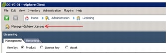 4. Add License keys for vCenter and Hosts
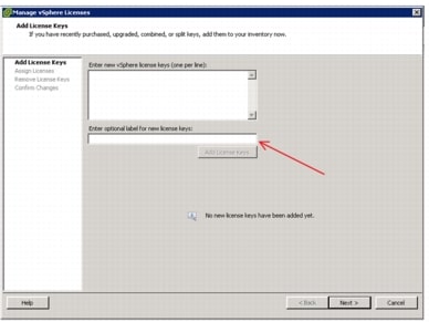
6.6.4 ESXi 5.0 Update 1 Cluster Configuration
To accommodate maximum recommendations for ESXi 5 clustering, we created two ESXi 5 clusters described below:
•
•
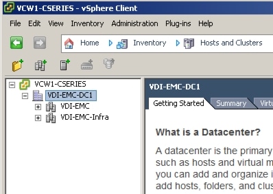
6.6.4.1 VDI-EMC- Infrastructure Cluster
The VDI-EMC-Infra cluster was used to host all of the virtualized servers within the VDA Infrastructure, including Active Directory servers providing authentication, DNS, DHCP and group policy services, a MS SQL 2008 R2 server for vCenter and XenDesktop databases, a pair of XenDesktop 5.6 FP1 servers, a file server for MS Roaming Profiles, a virtual file server for Login VSI files, and twenty Server 2008 R2 SP1 virtual machines as Login VSI Launchers.
Two physical UCS C220 M3 hosts were used in this cluster.
Standard ESXi vSwitches were used and configure as follows:
Managed FC Variant (All 10 Gb)* Default vmkernel vSwitch for VMware Management* Vmkernel vSwitch for VMotion* Standard vSwitch for VDI trafficUnmanaged NFS Variant* Default vmkernel vSwitch for VMware Management and VDI traffic (1 Gb)* Vmkernel vSwitch for vMotion (10 Gb)* Vmkernel vSwitch for NFS storage (10 Gb)It is not necessary to create an Infrastructure Cluster. If the existing Customer ESXi deployment has capacity, the required virtual machines can be added there.
Note
6.7.4.2 Virtual Desktop Clusters
A single vSohere cluster was used to host 600 virtual desktops:
•
The cluster was configured with a VMware ESXi 5 standard vSwitch providing the required network connectivity.
6.6.4.2 VDI-EMC Virtual Desktop Cluster
The VDI-EMC desktop cluster was used to host 600 of the Windows 7 SP1 32-bit virtual desktops.
Five physical Cisco UCS C220 M3 hosts were used in this cluster.
Standard ESXi vSwitches were used and configure as follows:
Managed FC Variant (All 10 Gb)* Default vmkernel vSwitch for VMware Management* Vmkernel vSwitch for VMotion* Standard vSwitch for VDI trafficUnmanaged NFS Variant* Default vmkernel vSwitch for VMware Management and VDI traffic (1 Gb)* Vmkernel vSwitch for vMotion (10 Gb)* Vmkernel vSwitch for NFS storage (10 Gb)We recommend creating a separate cluster for VDI workloads. It will provide a management container that will allow growth for the VDI use.
6.7 Installing and Configuring Citrix XenDesktop 5.6
Two XenDesktop 5.6 Delivery Controllers were virtualized on VMware ESXi 5.0 hosted on Cisco C220 M3 infrastructure blades. (Alternatively, they could be installed on Customer's existing ESXi 5.0 U1 hosts.)
Beginning with XenDesktop 5, Citrix replaced the proprietary IMA protocol encrypted data store in favor of Microsoft SQL Server databases. Concurrently the concept of XenDesktop Farms (used in XenDesktop 4 and earlier) was eliminated in favor of the concept of Sites.
From a management standpoint, Citrix introduced two new management consoles beginning with XenDesktop 5.
•
•
The Desktop Studio is the main administration console where hosts, machine catalogs, desktop groups and applications are created and managed. The Desktop Studio is where HDX policy is configured and applied to the site. The Desktop Studio is a Microsoft Management Console snap in and fully supports PowerShell.
6.7.1 Pre-requisites
The following is a list of pre-requisites that are required with installing XenDesktop 5.6. They are as follows:
•
–
–
Note that you can mix operating systems within a site.
•
•
•
–
–
If you do not have these on your server, you may be prompted for the Windows Server installation media, and they are installed for you.
•
•
•
•
•
•
Note
•
–
–
–
•
–
–
–
–
–
6.7.2 Install Citrix XenDesktop, Web Interface, Citrix XenDesktop Studio, and Optional Components
The steps identified below show the process used when installing XenDesktop, XenDesktop Studio and optional components
1. Start the XenDesktop installation wizard2. Click on Install XenDesktop
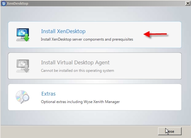 3. Accept the EULA and click Next
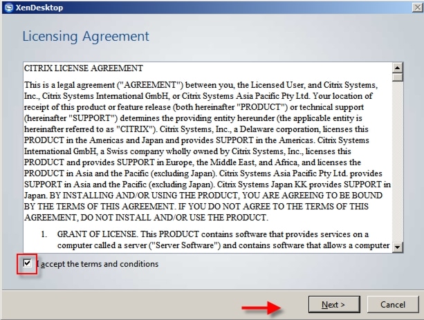 4. Select Components to install5. Verify that XenDesktop Controller, Web Access, Desktop Studio, Desktop Director and License Server are selected.6. If you have an existing Web Interface Server, Citrix License Server, or Microsoft SQL Server, uncheck the appropriate boxes, then, click Next. For this study, we unchecked the Install SQL Server Express checkbox.
Note
 7. Click "Next"8. If you are installing the License Server, note the firewall ports that need to be allowed, then click Next
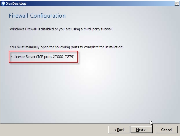 9. Click "Install" in the Summary page to continue installation.10. Click "OK" on the Installation Successful window to finalize your installation.
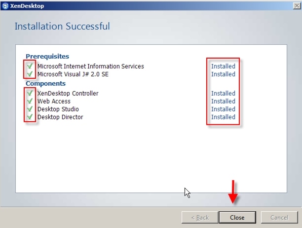
6.7.3 Configuring the License Server
1. Open the License Server Configuration Tool2. Accept the Default ports and provide the password for the Admin account
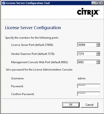 3. Click OK4. Go to Start | All Programs | Citrix | Management Consoles and click on License Administration Console
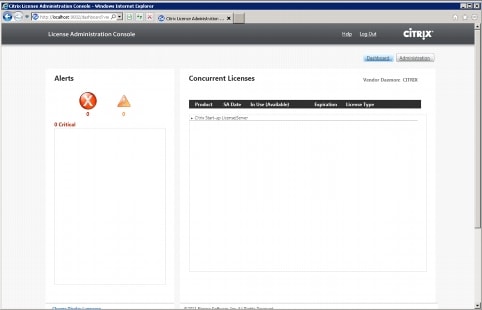 5. Click on the Administration button6. Enter the Admin credentials
 7. Click Submit8. Click on the Vendor Daemon Configuration tab on the left part of the screen
 9. Click on Import License10. Click Browse to locate the license file you are applying to the server
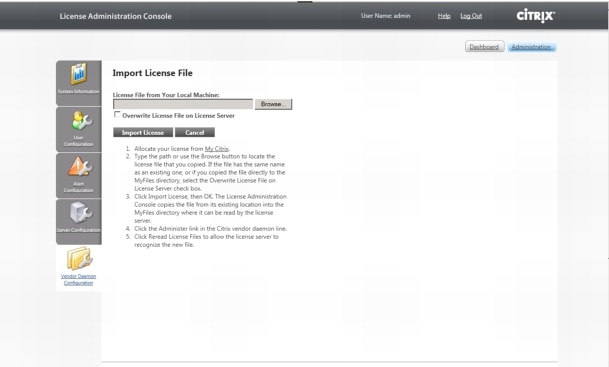 11. Select the file and Click Open12. Click on Import License13. Validate that the import was successful
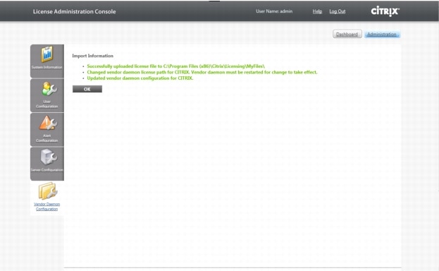 14. Click OK15. Click on the Dashboard button16. Validate that the necessary licenses have been installed
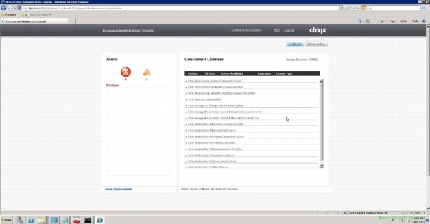
6.7.4 Create SQL Database for Citrix XenDesktop
1. After successfully installing XenDesktop, go to Start,>All Programs> Citrix>Desktop Studio (or if you checked the box Configure XenDesktop after Closing, it will launch automatically.)
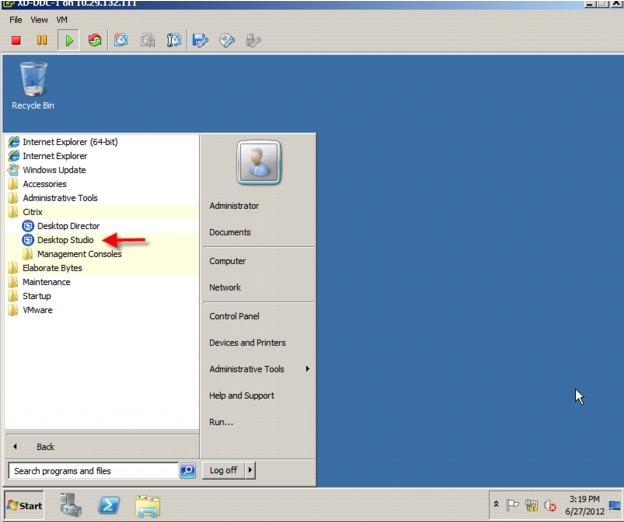 2. Click on Desktop deployment in the XenDesktop Wizard.
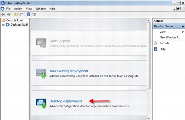 3. Name the Site
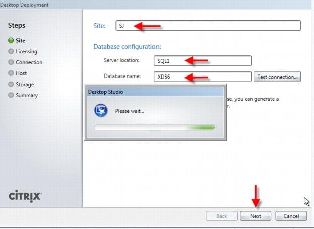 4. Database Configuration:
–
–
–
Note
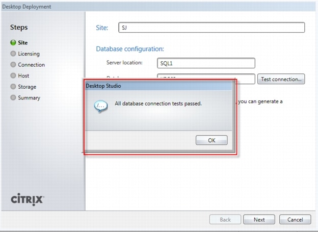 5. Click "Next".
When your first XenDesktop server is installed and configured, you can repeat the procedure in Section 6.7.2 Install XenDesktop above to create load balancing and a fault tolerant XenDesktop environment.
6.7.5 Configure the Citrix XenDesktop Site Hosts and Storage
1. Enter licensing server name or IP address, click Connect and select a license. Click "Next".
2. Select VMware Virtualization from the Host Type dropdown3. Enter VCenter URL information
Note
4. Enter the vCenter administrator user name and password.5. Click "Next".
6. Configure hostname and select cluster and Network (port profile on VMware)
7. Click "Next"8. Select storage - this correlates to your vCenter's Datastore.
Note
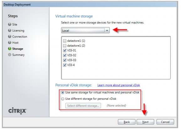 9. Click "Next"
10. Click "Finish"11. Create additional hosts per datastore & network.· Right click on your existing VCenter Storage "Host" connection· Select "Add Storage"· Select "Use an Existing Host connection"
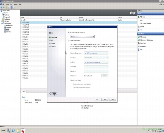
The configuration wizard will show the Initial configuration is now complete.
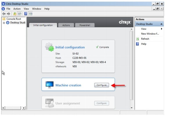
6.7.6 Configure Citrix XenDesktop HDX Polices
When testing with VSI a XenDesktop policy should be created to disable client printer mapping which is enabled by default. HDX policies configured and applied in Citrix Desktop Studio.
§ Open Desktop Studio, expand the Desktop Studio node§ Proceed to HDX Policy ‡ Users in the left pane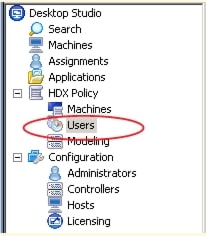 § Click "New.." in the center pane to start the policy creation process
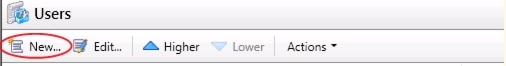 § Enter a name for your policy and click "Next"
 § Select from Categories ICA‡ Printing
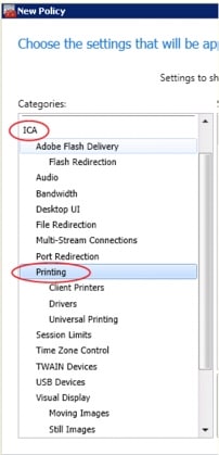 § Select Client printer redirection and click "add"
 § Click on "Prohibited" and then click "OK"
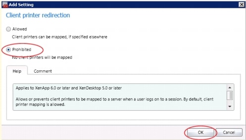 § Select from Categories ICA‡ Printing ‡ Client Printers
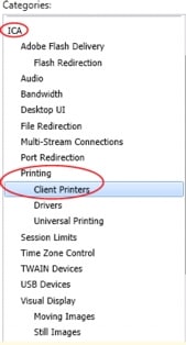 § Select "Auto-create client printers" and click "Add"
 § From the drop-down list, pick "Do not auto-create client printers" and click "OK"
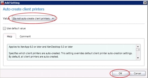 § Click "Next"
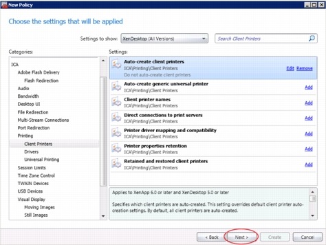 § Select All Filters ‡ "User or Group" and click "Add" Create policy filter
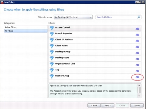 § Click "Add..."
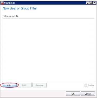 § Pick User Group you'll be applying this policy to
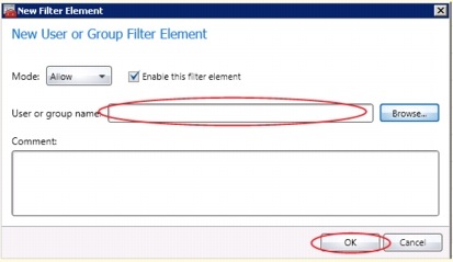 § Click "OK"
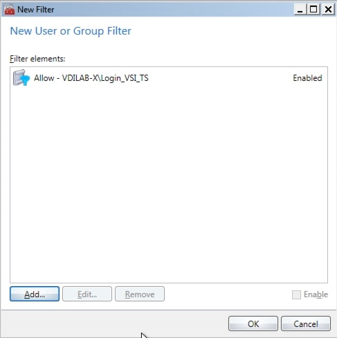 § Click "Next"
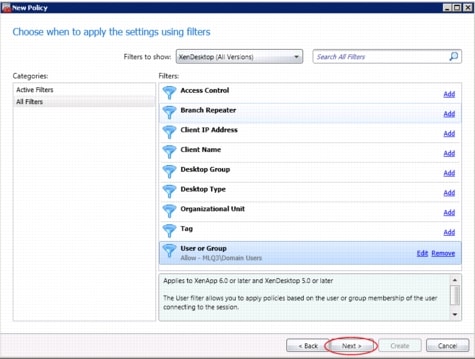 § Click "Create"
7 Desktop Delivery Infrastructure and Golden Image Creation
Many components are required to support the Virtual Desktop Infrastructure used in this project. This section details the key servers and their roles in the solution. Ultimately, XenDesktop 5.6 FP1 with Machine Creation Services managed the VDI environment in this project.
This section includes:
An overview of the component servers in the solution
User Profile Management
Creating the Windows 7 SP1 Golden Image
Using Machine Creation Services to create 600 virtual desktops
7.1 Overview of Solution Components
The image below provides a logical overview of the solution components in the environment.
Figure 18 Citrix XenDesktop 5.6 and Machine Creation Services Logical Diagram
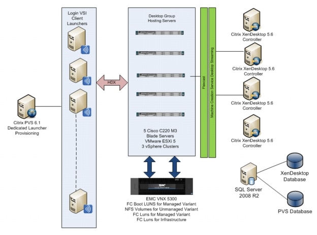
Summary of the Environment:
•
•
•
•
•
•
•
•
•
•
•
•
Storage on EMC VNX 7500.
•
•
•
•
The following tables provide details on the configuration of the solution components.
Table 7 Solution Component Configurations
7.2 File Servers for User Profile Management and Login VSI Share
We used one Microsoft Server 2008 R2 SP1 File Server for Microsoft Roaming User Profile storage for this testing. Customers who require resiliency can deploy clustered virtual machines.
Microsoft group policy was used to direct all user profiles to this server. A profile share was created on the machine following Microsoft best practices. Profiles were created for each user on first log on and downloaded to the virtual machine on subsequent logins.
For more information on best practices, see the article Best Practices for User Profiles:
http://technet.microsoft.com/en-us/library/cc784484(v=ws.10).aspx
A second Microsoft Server 2008 R2 SP1 File Server was deployed to house Login VSI shares. A shared folder was created to contain the necessary files for operations and data collection. This virtual machine is only required if Login VSI is deployed in the environment.
For more information on setting up the Login VSI share, see the following article, VSIshare Configuration:
http://www.loginvsi.com/documentation/v3/vsishare-configuration
7.3 Microsoft Windows 7 Golden Image Creation
7.3.1 Create Base Windows 7 SP1 32bit Virtual Machine
The Microsoft Windows 7 SP1 master or golden image with additional software was initially installed and prepared as a standard virtual machine on VMware ESXi prior to being used by XenDesktop 5.6 Machine Creation Services to deploy 600 virtual desktops.
With XenDesktop 5.6 the XenDesktop Setup Wizard was utilized.
The following section describes the process used to create the master or golden image and centralized Windows 7 vDisk used by Machine Creation Services.
Virtual Machine Base Software
•
•
•
•
7.3.2 Add Citrix XenDesktop 5.6 Virtual Desktop Agent
1. Copy the VDA executable to the local machine2. Launch executable3. Select Advanced Install4. Use default installation paths.5. Enter XenDesktop Delivery Controller's FQDN's.6. Click "Next".7. Do not install HDX or Citrix Receiver.8. Click "Finish".9. Remove VDA Welcome Screen program from the Windows Startup folder10. Restart VM11. Log in and check the event log to ensure that the DDC registration has successfully completed7.3.3 Add Login VSI Target Software (Login VSI Test Environments Only)
1. Launch setup wizard using run as Administrator2. Enter VSI share path3. Use default installation paths.4. Reboot after installation completes7.3.4 Citrix XenDesktop Optimizations
1. Delete XPS Printer2. Ensure that Bullzip PDF is the default printer3. Optimize· Configure SWAP file to 1536 MB (Cisco requirement)· Disable Windows Restore and serviceo Delete the restore points· Perform a disk cleanup· Disable Windows Firewall Service· Disable Windows Backup scheduled jobs· Open Computer Management | System Tools | Task Scheduler | Task Scheduler Library | Microsoft | Windows and disable the following:o Defrago Offline fileso Windows Backup· Windows Performance Settingso Smooth Edgeso Use Visual Styleso Show Translucento Show Window contents when dragging4. Modify Action Center settings (uncheck all warnings)5. Ensure that the Shadow Copy service is running and set to auto7.3.5 Perform additional PVS and XenDesktop Optimizations
1. Increased the ARP cache lifespan to 600 seconds for stream service bound NICs (article is located in Provisioning Services Reference documentation at the end of the document)2. Delete XPS Printer3. Ensure that Bullzip PDF is the default printer4. Optimize•
•
–
•
•
•
•
•
•
•
•
•
•
•
•
1. Modify Action Center settings (uncheck all warnings)2. Ensure that the Shadow Copy service is running and set to auto7.4 Virtual Machine Creation Using Citrix XenDesktop Machine Creation Services
When the golden image machine is created and optimized, shut it down and take a snapshot. We recommend cloning the machine to template as an added protection.
Follow this procedure to use XenDesktop Machine Creation Services to create 600 virtual machines:
1. Open the XenDesktop Studio Console and expand the Desktop Studio node in the navigation page2. Click the Machines node in the navigation page, then click Create Catalog in the Actions pane3. Select Pooled for the Machine Type, Random for the Machine Assignment, then click Next
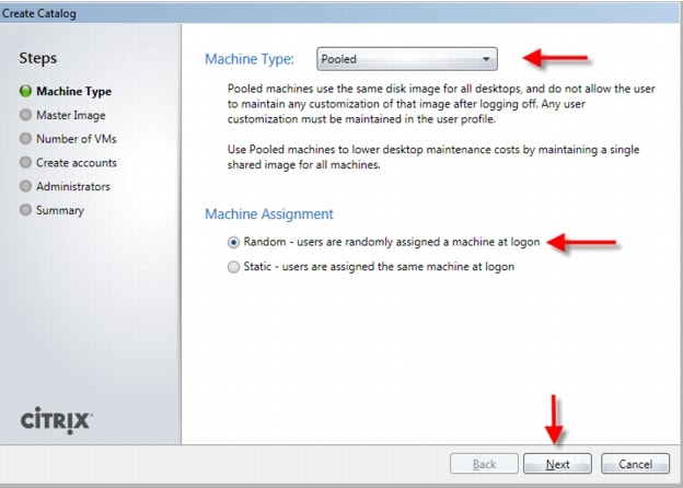 4. Click the golden image created earlier (not the template you may have also created) on the Select Master Image page, then click Next
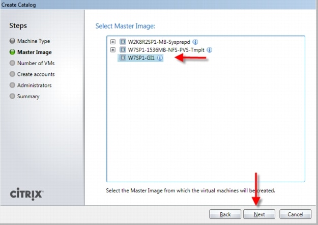 5. Enter the Number of vms to create, confirm the number of vCPUs and Memory, click Create new accounts, and then click Next
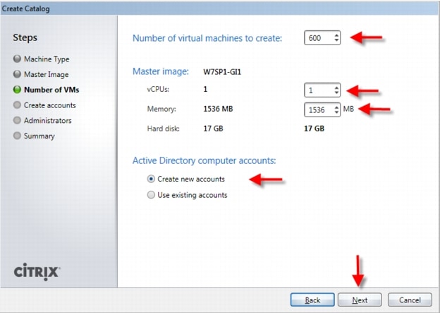 6. Select the Active Directory Domain, the location and a provide naming scheme, then click Next
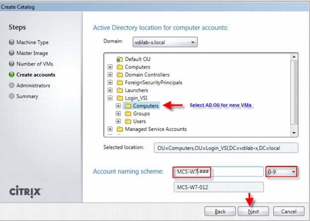 7. Add an optional description for the Catalog administrators, then click Next
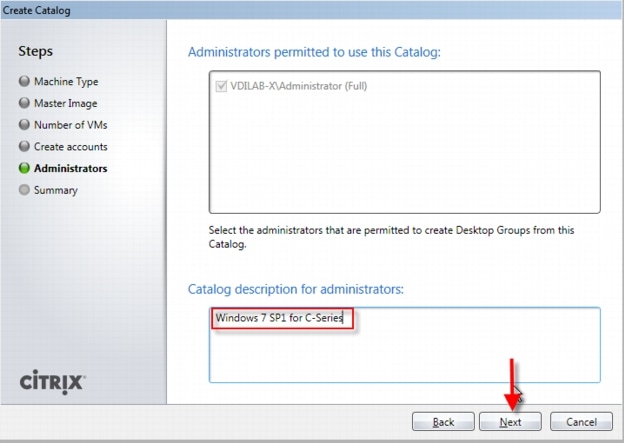 8. Provide a unique Catalog name, then click Next. Machine Creation Services copies the master image and provisions 600 virtual desktops.
 9. After the Catalog and its machines are created, click the Assignments node in the navigation pane, then Create Desktop Group in the action pane.10. Click the Catalog that was created previously and enter 600 in the Add machines input field, then click Next
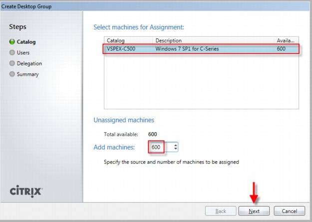 11. Click the Add button, select the users or groups to be authorized to use the Desktop Group and click Ok, select the number of Desktops per user to allocate, then click Next
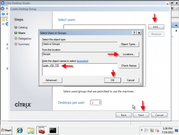 12. Click Next on the Delegate to page. (If there were multiple Administrators created, you could assign one or more as administrators of this Desktop Group)
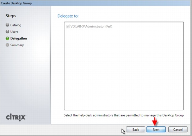 13. Enter a Display name and a Desktop Group name and click Finish
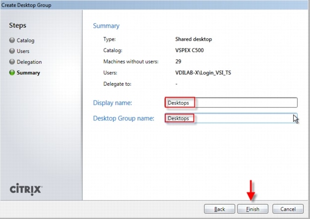 14. Your Desktop Group is created and you can use the XenDesktop Studio to control the behavior of your XenDesktop environment
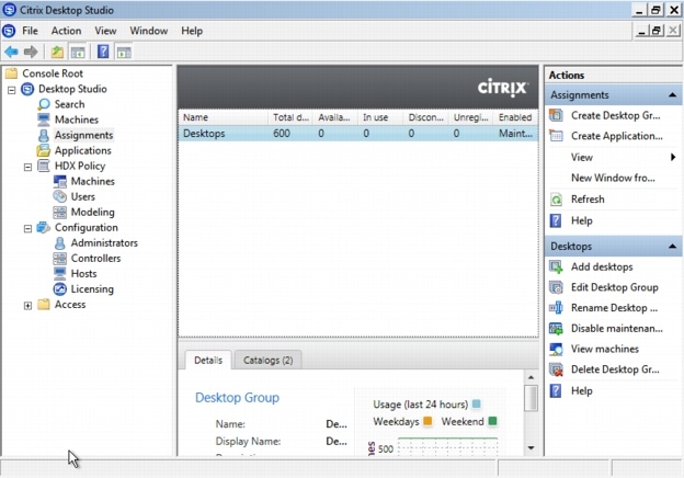 15. (Optional) You can configure your Hosts launch rate details. Rt-click the Hos in Configuration>Hosts. Select Change Details, Click Advanced
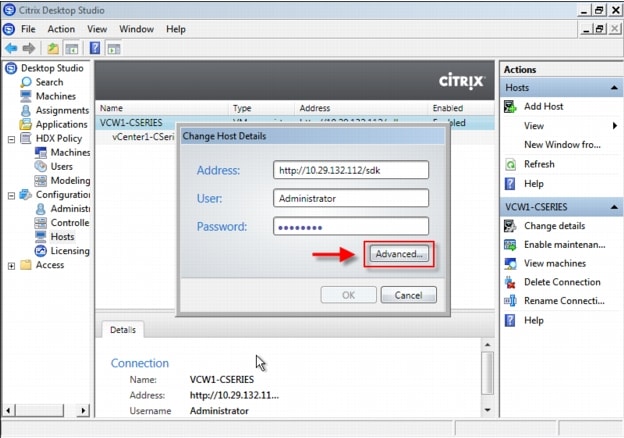 16. (Optional) You can modify how actions are taken by the desktop controller based on these settings using these controls. The default actions will start 10 desktops per minute. In the 600 desktop, 5 UCS C220 M3 VDI host environment, we set the Max new actions per minute to 50 and the Max active actions to 100. Click OK when you are finished.
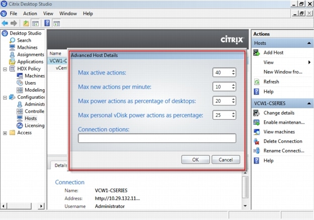 17. You should adjust the minimum number of desktops available for Weekdays and Weekends. You can do so by right-clicking the Desktop Group, selecting Edit Desktop Group, and click on the Power Management node. In our test environment, we wanted all 600 desktops powered on at all times during working hours.
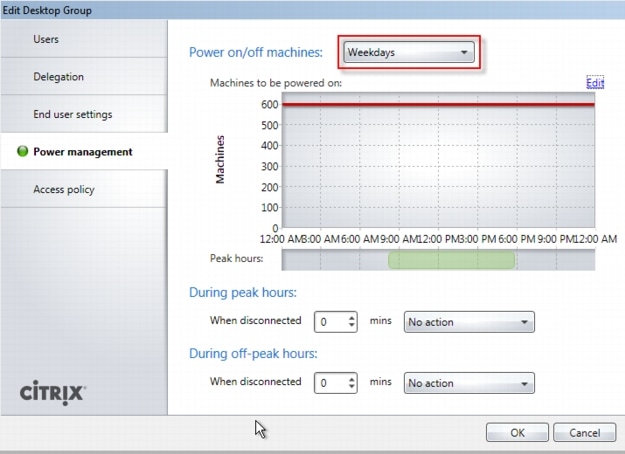
•
8 Test Setup and Configurations
In this project, we tested a single Cisco UCS C220 M3 Rack-Mount server and five Cisco UCS C220 M3 Rack-Mount servers to illustrate linear scalability in a 600 User configuration with N+1 Server Fault Tolerance.
8.1 Cisco UCS Test Configuration for Single Server Scalability
Figure 19 Cisco UCS C220 M3 Rack-Mount Server for Single Server Scalability

Hardware components
•
•
•
•
•
•
•
•
•
Software components
•
•
•
•
•
8.2 Cisco UCS Configuration for Five Server Test
Figure 20 600 Desktop Test Configuration-5 x Cisco UCS C220 M3 Rack-Mount Servers
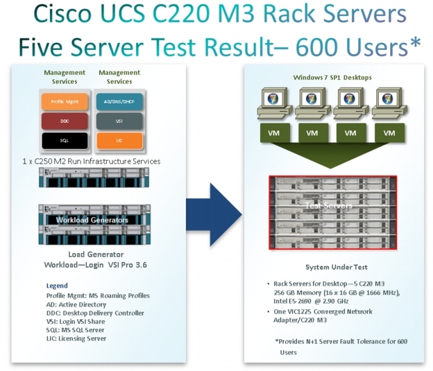
Hardware components
•
•
•
•
•
•
•
•
•
Software components
•
•
•
•
•
8.3 Testing Methodology and Success Criteria
All validation testing was conducted on-site within the Cisco Labs in San Jose, CA.
The testing results focused on the entire process of the virtual desktop lifecycle by capturing metrics during the desktop boot-up, user logon and virtual desktop acquisition (also referred to as ramp-up,) user workload execution (also referred to as steady state), and user logoff for the Hosted VDI model under test.
Test metrics were gathered from the hypervisor, virtual desktop, storage, and load generation software to assess the overall success of an individual test cycle. Each test cycle was not considered passing unless all of the planned test users completed the ramp-up and steady state phases (described below) and unless all metrics were within the permissible thresholds as noted as success criteria.
Three successfully completed test cycles were conducted for each hardware configuration and results were found to be relatively consistent from one test to the next.
8.3.1 Load Generation
Within each test environment, load generators were utilized to put demand on the system to simulate multiple users accessing the XenDesktop 5.6 environment and executing a typical end-user workflow. To generate load within the environment, an auxiliary software application was required to generate the end user connection to the XenDesktop environment, to provide unique user credentials, to initiate the workload, and to evaluate the end user experience.
In the Hosted VDI test environment, sessions launchers were used simulate multiple users making a direct connection to XenDesktop 5.6 via a Citrix HDX protocol connection.
8.3.2 User Workload SimulationLoginVSI From Login Consultants
One of the most critical factors of validating a XenDesktop deployment is identifying a real-world user workload that is easy for customers to replicate and standardized across platforms to allow customers to realistically test the impact of a variety of worker tasks. To accurately represent a real-world user workload, a third-party tool from Login Consultants was used throughout the Hosted VDI testing.
The tool has the benefit of taking measurements of the in-session response time, providing an objective way to measure the expected user experience for individual desktop throughout large scale testing, including login storms.
The Virtual Session Indexer (Login Consultants' Login VSI 3.6) methodology, designed for benchmarking Server Based Computing (SBC) and Virtual Desktop Infrastructure (VDI) environments is completely platform and protocol independent and hence allows customers to easily replicate the testing results in their environment. NOTE: In this testing, we utilized the tool to benchmark our VDI environment only.
Login VSI calculates an index based on the amount of simultaneous sessions that can be run on a single machine.
Login VSI simulates a medium workload user (also known as knowledge worker) running generic applications such as: Microsoft Office 2007 or 2010, Internet Explorer 8 including a Flash video applet and Adobe Acrobat Reader (Note: For the purposes of this test, applications were installed locally, not streamed nor hosted on XenApp).
Like real users, the scripted Login VSI session will leave multiple applications open at the same time. The medium workload is the default workload in Login VSI and was used for this testing. This workload emulated a medium knowledge working using Office, IE, printing and PDF viewing.
•
•
•
•
•
Each loop will open and use:
•
•
•
•
•
•
•
•
A graphical representation of the medium workload is shown below.
Graphical overview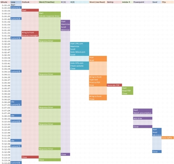
You can obtain additional information on Login VSI from http://www.loginvsi.com.
8.3.3 Testing Procedure
The following protocol was used for each test cycle in this study to insure consistent results.
8.3.3.1 Pre-Test Setup for Single and Multi-Blade Testing
All virtual machines were shut down utilizing the Citrix XenDesktop 5.6 Desktop Studio.
All Launchers for the test were shut down. They were then restarted in groups of 10 each minute until the required number of launchers was running with the Login VSI Agent at a "waiting for test to start" state.
All VMware ESXi 5.0 VDI host blades to be tested were restarted prior to each test cycle.
8.3.3.2 Test Run Protocol
To simulate severe, real-world environments, Cisco requires the log-on and start-work sequence, known as Ramp Up, to complete in 30 minutes. Additionally, we require all sessions started, whether 195 single server users or 600 full scale test users to become active within 2 minutes after the last session is launched.
In addition, Cisco requires that the Login VSI Parallel Launching method is used for all single server and scale testing. This assures that our tests represent real-world scenarios. (NOTE: The Login VSI Sequential Launching method allows the CPU, storage and network components to rest between each logins. This does not produce results that are consistent with the real-world scenarios that our Customers run in.)
For each of the three consecutive runs on single server (195 User) and 4 and 5 server (500 and 600 User) tests, the same process was followed:
1. Time 0:00:00 Started ESXtop Logging on the following systems:•
•
•
•
•
1. Time 0:00:10 Started EMC Basic Performance Logging on SPs2. Time 0:00:15 Started EMC NFS Performance Logging on Datamovers (Unmanaged NFS Variant Only)3. Time 0:05 Take 195, 500 or 600 desktops out of maintenance mode on XenDesktop Studio4. Time 0:06 First machines boot5. Time 0:26 195, 500 or 600 desktops booted on 1 or 5 servers6. Time 0:28 195, 500 or 600 desktops available on 1 or 5 servers7. Time 1:28 Start Login VSI 3.6 Test with 195, 500 or 600 desktops utilizing 7, 17 or 20 Launchers8. Time 1:58 195, 500 or 600 sessions launched9. Time 2:00 195, 500 or 600 sessions active10. Time 2:15 Login VSI Test Ends11. Time 2:30 195, 500 or 600 sessions logged off12. Time 2:35 All logging terminated.8.3.4 Success Criteria
There were multiple metrics that were captured during each test run, but the success criteria for considering a single test run as pass or fail was based on the key metric, VSI Max. The Login VSI Max evaluates the user response time during increasing user load and assesses the successful start-to-finish execution of all the initiated virtual desktop sessions.
8.3.4.1 Login VSI Max
VSI Max represents the maximum number of users the environment can handle before serious performance degradation occurs. VSI Max is calculated based on the response times of individual users as indicated during the workload execution. The user response time has a threshold of 4000ms and all users response times are expected to be less than 4000ms in order to assume that the user interaction with the virtual desktop is at a functional level. VSI Max is reached when the response times reaches or exceeds 4000ms for 6 consecutive occurrences. If VSI Max is reached, that indicates the point at which the user experience has significantly degraded. The response time is generally an indicator of the host CPU resources, but this specific method of analyzing the user experience provides an objective method of comparison that can be aligned to host CPU performance.
Note
8.3.4.2 Calculating VSIMax
Typically the desktop workload is scripted in a 12-14 minute loop when a simulated Login VSI user is logged on. After the loop is finished it will restart automatically. Within each loop the response times of seven specific operations is measured in a regular interval: six times in within each loop. The response times if these seven operations are used to establish VSImax. The seven operations from which the response times are measured are:
•
–
•
–
•
–
•
–
•
–
•
–
•
–
These measured operations with Login VSI do hit considerably different subsystems such as CPU (user and kernel), Memory, Disk, the OS in general, the application itself, print, GDI, etc. These operations are specifically short by nature. When such operations are consistently long: the system is saturated because of excessive queuing on any kind of resource. As a result, the average response times will then escalate. This effect is clearly visible to end-users. When such operations consistently consume multiple seconds the user will regard the system as slow and unresponsive.
With Login VSI 3.0 and later it is now possible to choose between `VSImax Classic' and 'VSImax Dynamic' results analysis. For these tests, we utilized VSImax Dynamic analysis.
8.3.4.3 VSIMax Dynamic
VSImax Dynamic is calculated when the response times are consistently above a certain threshold. However, this threshold is now dynamically calculated on the baseline response time of the test.
The following individual measurements are weighted to better support this approach:•
•
•
•
•
•
•
A sample of the VSImax Dynamic response time calculation is displayed below:
Then the average VSImax response time is calculated based on the amount of active Login VSI users logged on to the system. For this the average VSImax response times need to consistently higher than a dynamically calculated threshold.
To determine this dynamic threshold, first the average baseline response time is calculated. This is done by averaging the baseline response time of the first 15 Login VSI users on the system.
The formula for the dynamic threshold is: Avg. Baseline Response Time x 125% + 3000. As a result, when the baseline response time is 1800, the VSImax threshold will now be 1800 x 125% + 3000 = 5250ms.
Especially when application virtualization is used, the baseline response time can wildly vary per vendor and streaming strategy. Therefore it is recommend to use VSImax Dynamic when comparisons are made with application virtualization or anti-virus agents. The resulting VSImax Dynamic scores are aligned again with saturation on a CPU, Memory or Disk level, also when the baseline response time are relatively high.
8.3.4.5 Determining VSIMax
The Login VSI analyzer will automatically identify the "VSImax". In the example below the VSImax is 98. The analyzer will automatically determine "stuck sessions" and correct the final VSImax score.
•
•
Figure 21 Sample Login VSI Analyzer Graphic Output
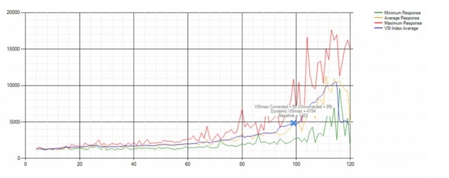
•
•
•
•
In our tests, the total number of users in the test run had to login, become active and run at least one test loop and log out automatically without reaching the VSI Max to be considered a success.
Note
Our Login VSI "pass" criteria, accepted by Login Consultants for this testing follows:
•
•
•
•
•
–
–
•
•
9 VDI Test Results
The purpose of this testing is to provide the data needed to validate Citrix XenDesktop 5.6 FP1 Hosted VDI FlexCast model and Citrix XenDesktop with Machine Creation Services using ESXi 5.0 Update 1 and vCenter 5.0 Update 1B to virtualize Microsoft Windows 7 SP1 desktops on Cisco UCS C220 M3 blade servers using a EMC VNX5300 storage system.
The information contained in this section provides data points that a customer may reference in designing their own implementations. These validation results are an example of what is possible under the specific environment conditions outlined here, and do not represent the full characterization of XenDesktop with VMware vSphere.
Two test sequences, each containing three consecutive test runs generating the same result, were performed to establish single server performance and multi-server, linear scalability.
One additional series of stress tests on a single blade server was conducted to establish the official Login VSI Max Score. To reach the Login VSI Max, we ran 195 Medium Workload (with flash) Windows 7 SP1 sessions on a single server. The Login VSI score was achieved on three consecutive runs and is shown below.
Figure 22 Login VSIMax Reached: 165 Users
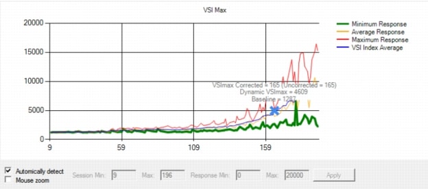
9.1 Cisco UCS Test Configuration for Single-Server Scalability Test Results
This section details the results from the XenDesktop Hosted VDI single blade server validation testing. The primary success criteria used to validate the overall success of the test cycle is an output chart from Login Consultants' VSI Analyzer Professional Edition, VSIMax Dynamic for the Medium workload (with Flash.)
Note
We ran the single server test at approximately 10 percent lower user density than prescribed by the Login VSI Max to achieve a successful pass of the test with server hardware performance in a realistic range.
The data below demonstrates that a single Cisco UCS C220 M3 is able to host 150 users sessions with average end user response times of under 2 seconds, well below the Login VSIMax Dynamic threshold for unacceptable performance.
This provides evidence that four Cisco UCS C220 M3s can handle the full 600 user compliment in the event that one of the five Cisco UCS C220 M3s prescribed for the 600 Users workload fails.
Similarly, for the alternate four Cisco UCS C220 500 User alternate solution, this data supports 450 Users can run on three Cisco UCS C220 M3s in the event that one of the four Cisco UCS C220 M3s fails.
Additionally, graphs detailing the CPU, Memory utilization and network throughput during peak session load are also presented. Given adequate storage capability, the CPU utilization determined the maximum VM density per blade.
Figure 23 150 Desktop Sessions on VMware ESXi 5.0U1 below 4000 ms

The following graphs detail CPU, Memory, Disk and Network performance on the Single Cisco UCS B230-M2 Blades
Figure 24 150 User Single Cisco UCS C220 M3 CPU Utilization Boot Phase
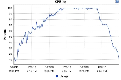
Figure 25 150 User Single Cisco UCS C220 M3 Available Memory
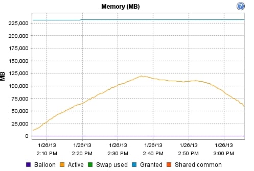
Figure 26 User Single Cisco UCS C220 M3 Cisco VIC1225 VIC Network Rates
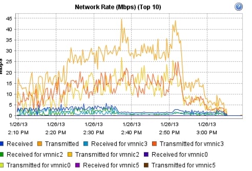
The following graphs detail performance of the EMC VNX 7500 during the single blade, 139 user test.
9.2 Cisco UCS Test Configuration for 600 Desktop Scalability Test Results
This section details the results from the XenDesktop Hosted VDI five rack server 600 user validation testing. It demonstrates linear scalability for the system. The primary success criteria used to validate the overall success of the test cycle is an output chart from Login Consultants' VSI Analyzer Professional Edition, VSIMax Dynamic for the Medium workload (with Flash.)
Note
We ran the multi-server test at an average user density slightly higher than 120 users per server across the system. One ESX Cluster containing 5 UCS C220 M3 servers ran the entire workload. This configuration provides N+1 fault tolerance on a cluster basis to achieve a successful pass of the test with server hardware performance in a realistic range.
Additionally, graphs detailing the CPU, Memory utilization and network throughput during peak session load are also presented for a representative blade running 120 user sessions. The single server graphs for blades running 120 user sessions are essentially the same. We have provided the remaining 4 UCS C220 M3 servers' performance charts in Appendix D to illustrate this point.
Given adequate storage capability, the CPU utilization determined the maximum recommended VM density per blade for the 600 user environment.
For the largest scale test, we are including the EMC VNX5300 performance metrics as well.
Figure 27 600 Desktop Sessions on 5 Cisco UCS C220 M3s running VMware ESXi 5.0 U1 below 4000 ms
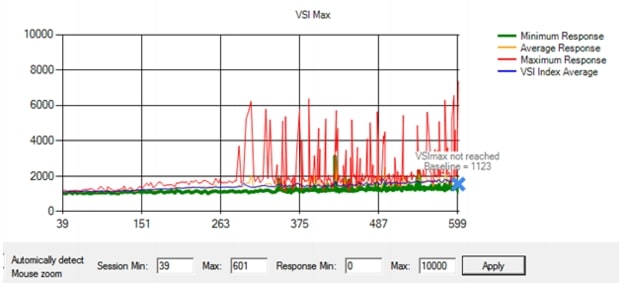
The following graphs detail CPU, Memory, Disk and Network performance on a representative Cisco UCS C220 M3 server during the five server, 600 User test. (Representative results for all five servers in one vCenter clusters can be found in Appendix C.)
Figure 28 600 Desktop Sessions on 5 Cisco UCS C220 M3 CPU Utilization Boot Phase

Figure 29 600 Desktop Sessions on 5 Cisco UCS C220 M3 Memory Utilization Boot Phase
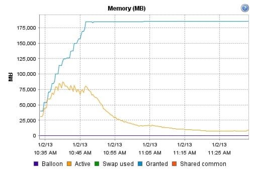
Figure 30 600 Desktop Sessions on 5 Cisco UCS C220 M3 Cisco VIC1225 Mbps Receive/Transmit Boot Phase
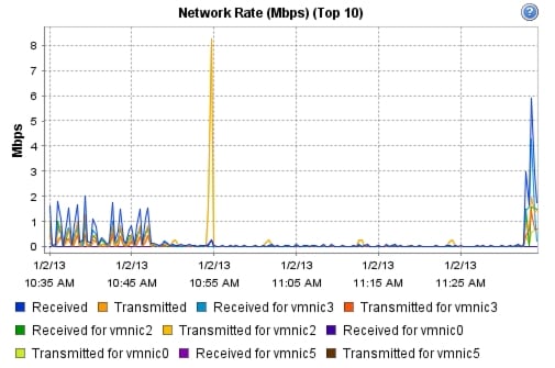
Figure 31 600 Desktop Sessions on 5 Cisco UCS C220 M3 CPU Utilization Test Phase
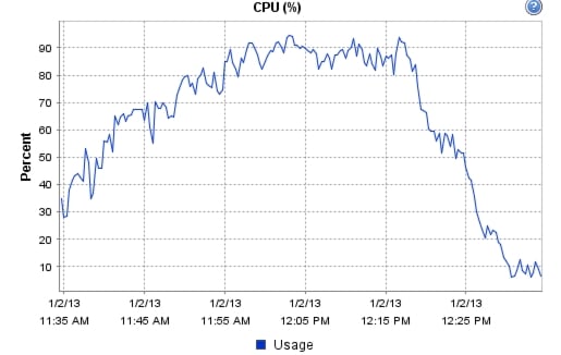
Figure 32 600 Desktop Sessions on 5 Cisco UCS C220 M3 CPU Utilization Test Phase
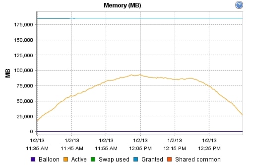
Figure 33 600 Desktop Sessions on 5 Cisco UCS C220 M3 Cisco VIC1225 Mbps Receive/Transmit Test Phase

Figure 34 600 Desktop Sessions on 5 Cisco UCS C220 M3 EMC VNX5300 SP Utilization Boot Phase
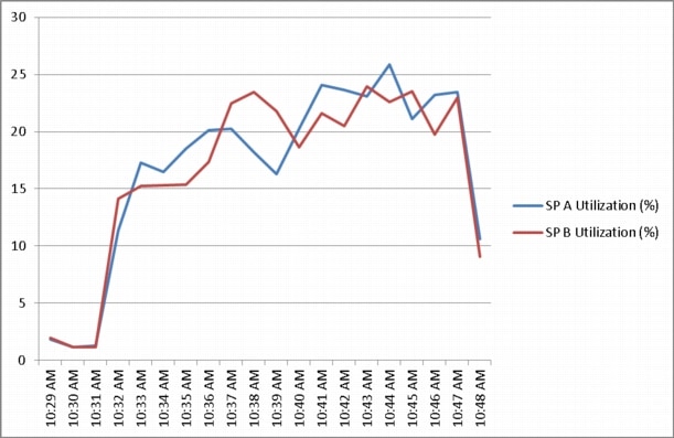
Figure 35 600 Desktop Sessions on 5 Cisco UCS C220 M3 EMC VNX5300 SP Queue Lengths Boot Phase
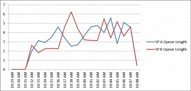
Figure 36 600 Desktop Sessions on 5 Cisco UCS C220 M3 EMC VNX5300 SP Total Throughput Boot Phase
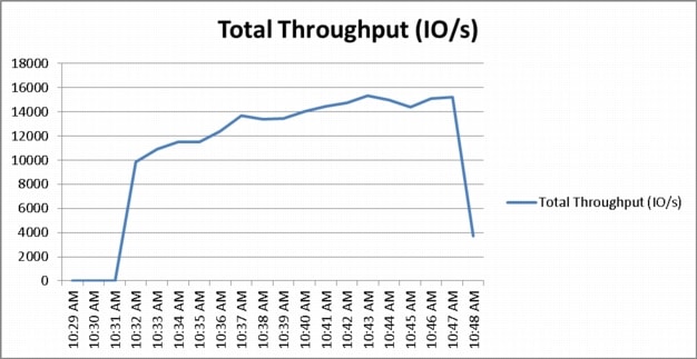
Figure 37 600 Desktop Sessions on 5 Cisco UCS C220 M3 EMC VNX5300 SP Utilization Test Phase
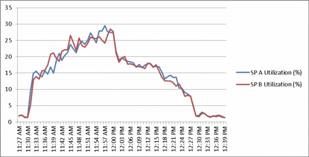
Figure 38 600 Desktop Sessions on 5 Cisco UCS C220 M3 EMC VNX5300 SP Queue Lengths Test Phase
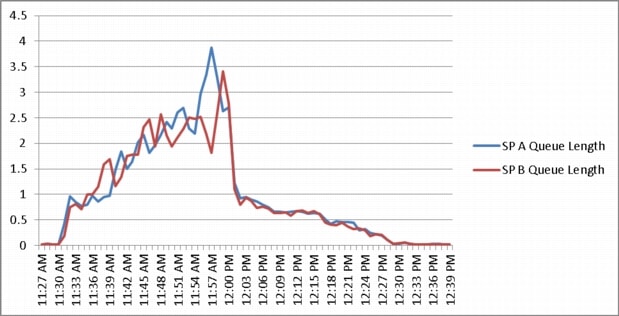
Figure 39 600 Desktop Sessions on 5 Cisco UCS C220 M3 EMC VNX5300 SP Total Throughput Test Phase
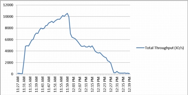
9.3 Cisco UCS Test Configuration for 500 Desktop Scalability Test Results
This section details the results from the XenDesktop Hosted VDI four rack server 500 user validation testing. It demonstrates linear scalability for the system. The primary success criteria used to validate the overall success of the test cycle is an output chart from Login Consultants' VSI Analyzer Professional Edition, VSIMax Dynamic for the Medium workload (with Flash.)
Note
We ran the multi-server test at an average user density of 125 users per server across the system. One ESX Cluster containing 4 Cisco UCS C220 M3 servers ran the entire workload. This configuration provides N+1 fault tolerance for 450 users to achieve a successful pass of the test with server hardware performance in a realistic range.
Additionally, graphs detailing the CPU, Memory utilization and network throughput during peak session load are also presented for a representative server running 125 user sessions. The single server graphs for blades running 125 user sessions are essentially the same. We have provided the remaining 3 UCS C220 M3 servers' performance charts in Appendix D to illustrate this point.
Given adequate storage capability, the CPU utilization determined the maximum recommended VM density per blade for the 500 user environment.
Figure 40 500 Desktop Sessions on 4 Cisco UCS C220 M3s running VMware ESXi 5.0U1 below 4000 ms
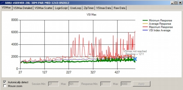
Figure 41 500 Desktop Sessions on 4 C220 M3 CPU Utilization Boot Phase

Figure 42 500 Desktop Sessions on 5 C220 M3 Memory Utilization Boot Phase

Figure 43 500 Desktop Sessions on 5 C220 M3 Network Utilization Boot Phase

Figure 44 500 Desktop Sessions on 4 C220 M3 CPU Utilization Test Phase
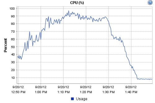
Figure 45 500 Desktop Sessions on 4 C220 M3 Memory Utilization Test Phase
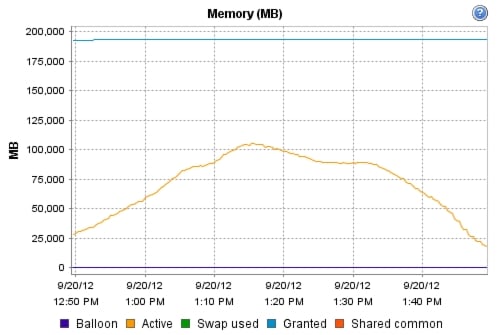
Figure 46 500 Desktop Sessions on 4 C220 M3 Network Utilization Test Phase
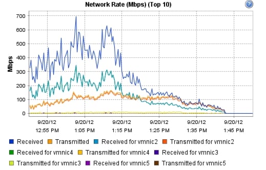
10 Scalability Considerations and Guidelines
There are many factors to consider when you begin to scale beyond a 500-600 User, four to five Cisco UCS C220 host server configuration, which this reference architecture has successfully tested. In this section we give guidance to scale beyond the 500-600 user system.
10.1 Cisco UCS System Configuration
As our results indicate, we have proven linear scalability in the Cisco UCS Reference Architecture as tested.
•
•
•
•
Of course, the backend storage has to be scaled accordingly, based on the IOP considerations as described in the EMC scaling section. Please refer the EMC section that follows this one for scalability guidelines.
10.2 Citrix XenDesktop 5.6 Hosted VDI
XenDesktop environments can scale to large numbers. When implementing Citrix XenDesktop hosted VDI considerations include but not limited to:
•
•
•
•
These and other various aspects of scalability considerations described in greater detail in "XenDesktop - Modular Reference Architecture" document and should be a part of any VDI design.
Designing and deploying our test environment we followed best practices whenever possible.
The following are in particular worth mentioning here.
Citrix always recommends using N+1 schema for VDI servers, to accommodate resiliency. In our test environment, this was applied to all infrastructure servers.
For larger scale deployments, Provisioning Server Network Adapters were configured to have a static IP and management and streaming traffic was separated between different Network adapters.
For larger scale deployments, all the PVS services are set to start as: Automatic (Delayed Start).
For larger scale deployments, we use the XenDesktop Setup Wizard in PVS. Wizard does an excellent job of creating the desktops automatically and it's possible to run multiple instances of the wizard provided the deployed desktops are placed in different catalogs and have different naming conventions.
To run wizard at a minimum you need to install the Provisioning Server, the XenDesktop Controller, and configure hosts, as well as create VM templates on all datastores were desktops will be deployed.
10.3 EMC VNX Storage Guidelines for XenDesktop Virtual Machines
Sizing VNX storage system to meet virtual desktop IOPS requirement is a complicated process. When an I/O reaches the VNX storage, it is served by several components such as Data Mover (NFS), backend dynamic random access memory (DRAM) cache, FAST Cache, and disks. To reduce the complexity, EMC recommends using a building block approach to scale to thousands of virtual desktops.
For more information on storage sizing guidelines to implement virtual desktop infrastructure in VNX unified storage systems, refer to the EMC white paper "Sizing EMC VNX Series for VDI workload - An Architectural Guideline."
10.4 VMware ESXi 5 Guidelines for Virtual Desktop Infrastructure
In our test environment two adjustments were performed to support our scale:
The amount of memory configured for the Tomcat Maximum memory pool was increased to 3072.
The cost threshold for parallelism was increased to 15.
For further explanations on a basis for these adjustments and details on how to perform them refer to the VMware documentation sited in References section of this document.
11 References
This section provides links to additional information for each partner's solution component of this document.
11.1 Cisco Reference Documents
Third-Generation Fabric Computing: The Power of Unification webcast replay
http://tools.cisco.com/gems/cust/customerSite.do?METHOD=W&LANGUAGE_ID=E&PRIORITY_CODE=215011_15&SEMINAR_CODE=S15897&CAMPAIGN=UCS+Momentum&COUNTRY_SITE=us&POSITION=banner&REFERRING_SITE=go+unified+computing&CREATIVE=carousel+banner+event+replayCisco Unified Computing System Manager Home Page
Cisco UCS C220 M3 Rack Server Resources
Cisco UCS 6200 Series Fabric Interconnects
Cisco Nexus 2232PP 10GE Fabric Extender
Cisco Nexus 5500 Series Switches Resources
Download Software for UCS C220 M3 Rack Server
Download Cisco UCS Manager and Blade Software Version 2.0(4d)
Download Cisco UCS Central Software Version 1.0(1a)
http://software.cisco.com/download/cart.html?imageGuId=8CAAAD77B3A1DB35B157BE84ED109A4703849F53&i=rs11.2 Citrix Reference Documents
XenDesktop 5.6
•
Virtual Desktop
•
•
11.3 EMC Reference Documents
•
•
•
•
•
•
•
11.4 VMware Reference Documents
•
•
•
•
•
Appendix A—Nexus 5548 Configuration (NFS Variant Only)
!Nexus 5548A NFS Variant VSPEX C500
!Command: show running-config
!Time: Sun Dec 6 23:15:29 2009
version 5.1(3)N1(1a)
hostname SJ2-B21-N5548-A
feature telnet
no feature http-server
cfs eth distribute
feature interface-vlan
feature hsrp
feature lacp
feature vpc
feature lldp
feature fex
username admin password 5 $1$ZGA7bQiM$rD7QcH45.4ZOLIf2/J.ur1 role network-adminno password strength-check
banner motd #Nexus 5000 Switch
#
ip domain-lookup
ip domain-name cisco.com
ip name-server 171.70.168.183 171.68.226.120
system jumbomtu 9000
logging event link-status default
class-map type qos class-fcoe
class-map type qos match-any class-platinum
match cos 5
class-map type queuing class-fcoe
match qos-group 1
class-map type queuing class-platinum
match qos-group 2
class-map type queuing class-all-flood
match qos-group 2
class-map type queuing class-ip-multicast
match qos-group 2
policy-map type qos jumbo
class class-default
set qos-group 0
policy-map type qos system_qos_policy
class class-platinum
set qos-group 2
class class-default
set qos-group 0
policy-map type queuing system_q_in_policy
class type queuing class-platinum
bandwidth percent 50
class type queuing class-fcoe
bandwidth percent 20
class type queuing class-default
bandwidth percent 30
policy-map type queuing system_q_out_policy
class type queuing class-platinum
bandwidth percent 50
class type queuing class-fcoe
bandwidth percent 20
class type queuing class-default
bandwidth percent 30
class-map type network-qos class-fcoe
match qos-group 1
class-map type network-qos class-platinum
match qos-group 2
class-map type network-qos class-all-flood
match qos-group 2
class-map type network-qos system_nq_policy
match qos-group 2
class-map type network-qos class-ip-multicast
match qos-group 2
policy-map type network-qos system_nq_policy
class type network-qos class-platinum
pause no-drop
mtu 9000
class type network-qos class-fcoe
pause no-drop
mtu 2158
class type network-qos class-default
mtu 9000
multicast-optimize
system qos
service-policy type qos input system_qos_policy
service-policy type queuing input system_q_in_policy
service-policy type queuing output system_q_out_policy
service-policy type network-qos system_nq_policy
fex 130
pinning max-links 1
description "FEX0130"
snmp-server user admin network-admin auth md5 0x0ae428b6495ff67f478fd90e941c15d7 priv
0x0ae428b6495ff67f478fd90e941c15d7 localizedkey
vrf context management
ip route 0.0.0.0/0 10.29.132.1
vlan 1
vlan 47
name N1K-Mgmt
vlan 48
name N1K-Ctrl
vlan 49
name N1K-Pckt
vlan 50
name Storage
vlan 51
name vMotion
vlan 52
name VDIAB
vlan 100
name VDI
vlan 132
name ESXi_Management
spanning-tree vlan 1,10-20,50-52,100,132 priority 16384
vpc domain 30
role priority 4000
peer-keepalive destination 10.29.132.6
interface Vlan1
interface Vlan50
no shutdown
ip address 10.10.50.3/24
hsrp version 2
hsrp 50
preempt
priority 110
ip 10.10.50.1
interface Vlan51
no shutdown
ip address 10.10.51.3/24
hsrp version 2
hsrp 51
preempt
priority 110
ip 10.10.51.1
interface Vlan52
no shutdown
ip address 10.10.52.3/24
hsrp version 2
hsrp 52
preempt
priority 110
ip 10.10.52.1
interface Vlan100
no shutdown
ip address 10.10.1.3/22
hsrp version 2
hsrp 100
preempt
priority 110
ip 10.10.1.1
interface port-channel2
untagged cos 5
switchport access vlan 50
vpc 2
interface port-channel30
switchport mode trunk
switchport trunk allowed vlan 47-52,100,132
spanning-tree port type network
vpc peer-link
interface port-channel47
description VPCforN1KVUplinks
switchport mode trunk
switchport trunk allowed vlan 47-52,100,132
spanning-tree port type edge trunk
speed 10000
vpc 47
interface Ethernet1/1
switchport access vlan 132
speed 1000
interface Ethernet1/2
interface Ethernet1/3
description N1K-UplinkforInfraServers
switchport access vlan 100
interface Ethernet1/4
switchport mode trunk
switchport access vlan 51
switchport trunk allowed vlan 47-52,100,132
speed 1000
interface Ethernet1/5
switchport mode trunk
switchport trunk allowed vlan 47-52,100,132
interface Ethernet1/6
switchport mode trunk
switchport trunk allowed vlan 47-52,100,132
interface Ethernet1/7
switchport mode trunk
switchport trunk allowed vlan 47-52,100,132
interface Ethernet1/8
switchport mode trunk
switchport trunk allowed vlan 47-52,100,132
interface Ethernet1/9
switchport mode trunk
switchport trunk allowed vlan 47-52,100,132
interface Ethernet1/10
switchport mode trunk
switchport trunk allowed vlan 47-52,100,132
interface Ethernet1/11
interface Ethernet1/12
interface Ethernet1/13
switchport access vlan 100
speed 1000
interface Ethernet1/14
switchport access vlan 100
speed 1000
interface Ethernet1/15
switchport access vlan 100
speed 1000
interface Ethernet1/16
switchport access vlan 100
speed 1000
interface Ethernet1/17
switchport access vlan 100
speed 1000
interface Ethernet1/18
switchport access vlan 100
speed 1000
interface Ethernet1/19
switchport access vlan 100
speed 1000
interface Ethernet1/20
switchport access vlan 100
speed 1000
interface Ethernet1/21
interface Ethernet1/22
interface Ethernet1/23
interface Ethernet1/24
interface Ethernet1/25
interface Ethernet1/26
interface Ethernet1/27
interface Ethernet1/28
interface Ethernet1/29
interface Ethernet1/30
shutdown
switchport mode fex-fabric
fex associate 130
interface Ethernet1/31
switchport mode trunk
switchport trunk allowed vlan 47-52,100,132
channel-group 30 mode active
interface Ethernet1/32
switchport mode trunk
switchport trunk allowed vlan 47-52,100,132
channel-group 30 mode active
interface Ethernet2/1
description VNX-5300-10GB-UPLINK
switchport access vlan 50
channel-group 2 mode active
interface Ethernet2/2
description VNX-5300-10GB-UPLINK
switchport access vlan 50
interface Ethernet2/3
interface Ethernet2/4
interface Ethernet2/5
interface Ethernet2/6
interface Ethernet2/7
interface Ethernet2/8
interface mgmt0
ip address 10.29.132.7/24
line console
line vty
boot kickstart bootflash:/n5000-uk9-kickstart.5.1.3.N1.1a.bin
boot system bootflash:/n5000-uk9.5.1.3.N1.1a.bin
Appendix B—Server Performance Metrics for 500 Users on 4 Cisco UCS C220 M3 Servers
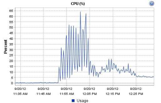
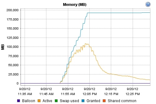
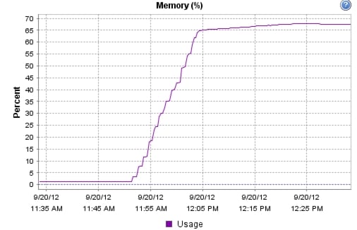
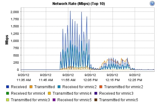
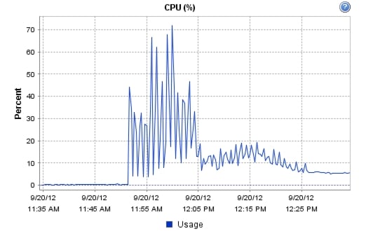


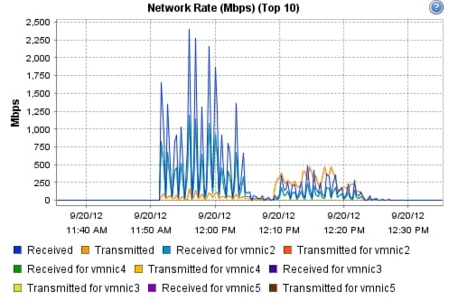
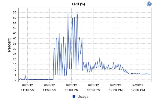

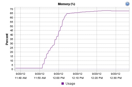
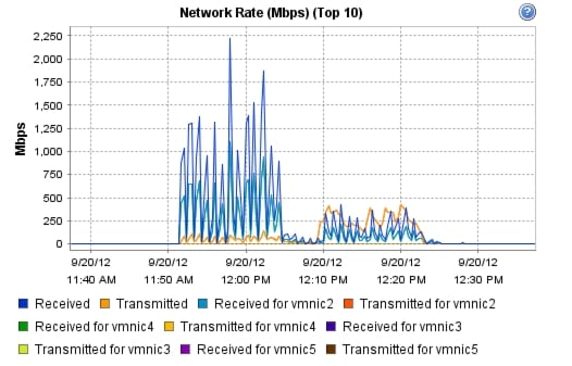
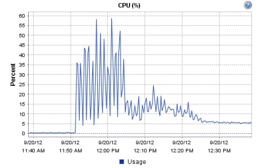
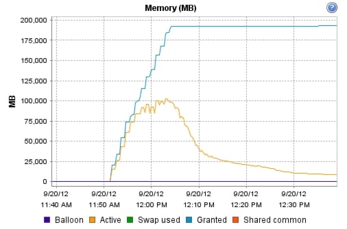
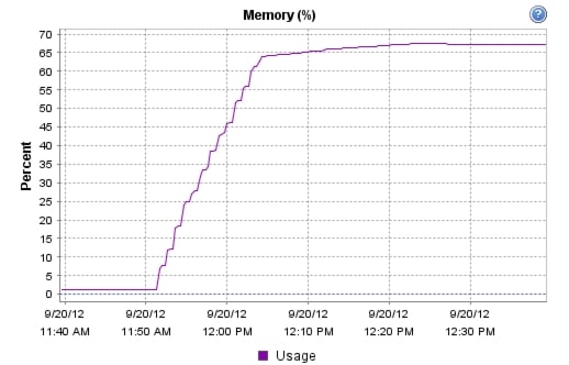


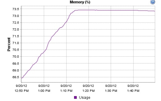

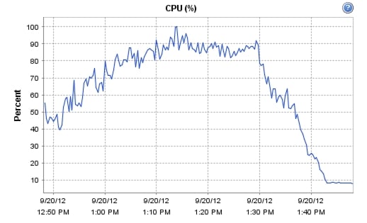
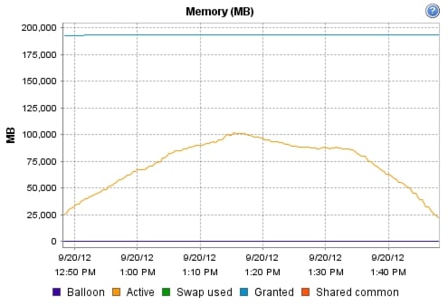
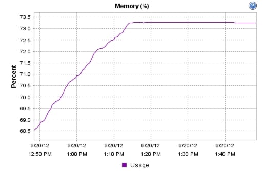
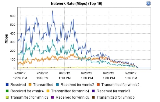

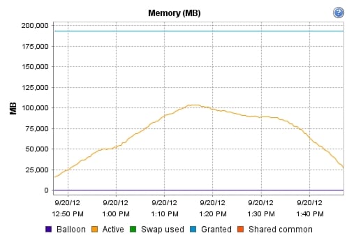
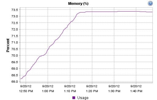
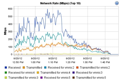
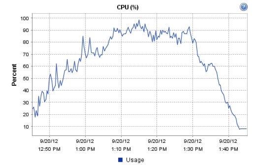
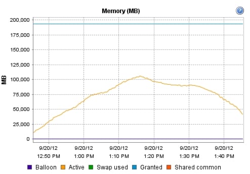

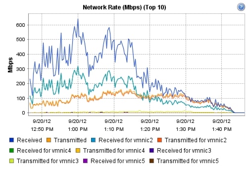
!Nexus 5548B NFS Variant VSPEX C500
!Command: show running-config
!Time: Wed Dec 9 23:12:09 2009
version 5.1(3)N1(1a)
hostname SJ2-B21-N5548-B
feature telnet
no feature http-server
cfs eth distribute
feature interface-vlan
feature hsrp
feature lacp
feature vpc
feature lldp
feature fex
username admin password 5 $1$aWEymjJt$zqib1M7FZGO9ExVR6EHWg. role network-adminno password strength-check
banner motd #Nexus 5000 Switch
#
ip domain-lookup
ip domain-name cisco.com
ip name-server 171.70.168.183 171.68.226.120
system jumbomtu 9000
logging event link-status default
class-map type qos class-fcoe
class-map type qos match-any class-platinum
match cos 5
class-map type queuing class-fcoe
match qos-group 1
class-map type queuing class-platinum
match qos-group 2
class-map type queuing class-all-flood
match qos-group 2
class-map type queuing class-ip-multicast
match qos-group 2
policy-map type qos jumbo
class class-default
set qos-group 0
policy-map type qos system_qos_policy
class class-platinum
set qos-group 2
class class-default
set qos-group 0
policy-map type queuing system_q_in_policy
class type queuing class-platinum
bandwidth percent 50
class type queuing class-fcoe
bandwidth percent 20
class type queuing class-default
bandwidth percent 30
policy-map type queuing system_q_out_policy
class type queuing class-platinum
bandwidth percent 50
class type queuing class-fcoe
bandwidth percent 20
class type queuing class-default
bandwidth percent 30
class-map type network-qos class-fcoe
match qos-group 1
class-map type network-qos class-platinum
match qos-group 2
class-map type network-qos class-all-flood
match qos-group 2
class-map type network-qos system_nq_policy
match qos-group 2
class-map type network-qos class-ip-multicast
match qos-group 2
policy-map type network-qos system_nq_policy
class type network-qos class-platinum
pause no-drop
mtu 9000
class type network-qos class-fcoe
pause no-drop
mtu 2158
class type network-qos class-default
mtu 9000
multicast-optimize
system qos
service-policy type qos input system_qos_policy
service-policy type queuing input system_q_in_policy
service-policy type queuing output system_q_out_policy
service-policy type network-qos system_nq_policy
fex 130
pinning max-links 1
description "FEX0130"
snmp-server user admin network-admin auth md5 0x371b3192e7f154d1814e1748d100326c priv
0x371b3192e7f154d1814e1748d100326c localizedkey
vrf context management
ip route 0.0.0.0/0 10.29.132.1
vlan 1
vlan 47
name N1K-Mgmt
vlan 48
name N1K-Ctrl
vlan 49
name N1K-Pkt
vlan 50
name Storage
vlan 51
name vMotion
vlan 52
name VDIAB
vlan 100
name VDI
vlan 132
name ESXi_Management
spanning-tree vlan 1,10-20,50-52,100,132 priority 20480
vpc domain 30
role priority 4000
peer-keepalive destination 10.29.132.7
interface Vlan1
interface Vlan50
no shutdown
ip address 10.10.50.2/24
hsrp version 2
hsrp 50
preempt
ip 10.10.50.1
interface Vlan51
no shutdown
ip address 10.10.51.2/24
hsrp version 2
hsrp 51
preempt
ip 10.10.51.1
interface Vlan52
no shutdown
ip address 10.10.52.2/24
hsrp version 2
hsrp 52
preempt
ip 10.10.52.1
interface Vlan100
no shutdown
ip address 10.10.1.2/22
hsrp version 2
hsrp 100
preempt
ip 10.10.1.1
interface port-channel2
untagged cos 5
switchport access vlan 50
vpc 2
interface port-channel30
switchport mode trunk
switchport trunk allowed vlan 47-52,100,132
spanning-tree port type network
vpc peer-link
interface Ethernet1/1
switchport access vlan 132
speed 1000
interface Ethernet1/2
interface Ethernet1/3
description N1K-UplinkforInfraServers
switchport access vlan 100
interface Ethernet1/4
interface Ethernet1/5
switchport mode trunk
switchport trunk allowed vlan 47-52,100,132
interface Ethernet1/6
switchport mode trunk
switchport trunk allowed vlan 47-52,100,132
interface Ethernet1/7
switchport mode trunk
switchport trunk allowed vlan 47-52,100,132
interface Ethernet1/8
switchport mode trunk
switchport trunk allowed vlan 47-52,100,132
interface Ethernet1/9
switchport mode trunk
switchport trunk allowed vlan 47-52,100,132
interface Ethernet1/10
switchport mode trunk
switchport trunk allowed vlan 47-52,100,132
interface Ethernet1/11
interface Ethernet1/12
interface Ethernet1/13
interface Ethernet1/14
interface Ethernet1/15
interface Ethernet1/16
interface Ethernet1/17
interface Ethernet1/18
interface Ethernet1/19
interface Ethernet1/20
interface Ethernet1/21
interface Ethernet1/22
interface Ethernet1/23
interface Ethernet1/24
interface Ethernet1/25
interface Ethernet1/26
interface Ethernet1/27
interface Ethernet1/28
interface Ethernet1/29
switchport mode fex-fabric
fex associate 130
interface Ethernet1/30
switchport mode fex-fabric
fex associate 130
interface Ethernet1/31
switchport mode trunk
switchport trunk allowed vlan 47-52,100,132
channel-group 30 mode active
interface Ethernet1/32
switchport mode trunk
switchport trunk allowed vlan 47-52,100,132
channel-group 30 mode active
interface Ethernet2/1
description VNX-5300-10GB-UPLINK
switchport access vlan 50
channel-group 2 mode active
interface Ethernet2/2
description VNX-5300-10GB-UPLINK
switchport access vlan 50
interface Ethernet2/3
interface Ethernet2/4
interface Ethernet2/5
interface Ethernet2/6
interface Ethernet2/7
interface Ethernet2/8
interface mgmt0
ip address 10.29.132.6/24
line console
line vty
boot kickstart bootflash:/n5000-uk9-kickstart.5.1.3.N1.1a.bin
boot system bootflash:/n5000-uk9.5.1.3.N1.1a.bin