Table Of Contents
About Cisco Validated Design (CVD) Program
VMware vSphere Built On FlexPod With IP-Based Storage
Benefits of Cisco Unified Computing System
Benefits of Cisco Nexus 5548UP
Benefits of the NetApp FAS Family of Storage Controllers
Benefits of OnCommand Unified Manager Software
Benefits of VMware vSphere with the NetApp Virtual Storage Console
NetApp FAS2240-2 Deployment Procedure: Part 1
Assign Controller Disk Ownership
Install Data ONTAP to Onboard Flash Storage
Harden Storage System Logins and Security
Enable Active-Active Controller Configuration Between Two Storage Systems
Set Up Storage System NTP Time Synchronization and CDP Enablement
Create an SNMP Requests Role and Assign SNMP Login Privileges
Create an SNMP Management Group and Assign an SNMP Request Role
Create an SNMP User and Assign It to an SNMP Management Group
Set Up SNMP v1 Communities on Storage Controllers
Set Up SNMP Contact Information for Each Storage Controller
Set SNMP Location Information for Each Storage Controller
Reinitialize SNMP on Storage Controllers
Initialize NDMP on the Storage Controllers
Set 10GbE Flow Control and Add VLAN Interfaces
Export NFS Infrastructure Volumes to ESXi Servers
Cisco Nexus 5548 Deployment Procedure
Set up Initial Cisco Nexus 5548 Switch
Enable Appropriate Cisco Nexus Features
Add Individual Port Descriptions for Troubleshooting
Add PortChannel Configurations
Configure Virtual PortChannels
Uplink Into Existing Network Infrastructure
Cisco Unified Computing System Deployment Procedure
Perform Initial Setup of Cisco UCS C-Series Servers
Perform Initial Setup of the Cisco UCS 6248 Fabric Interconnects
Upgrade Cisco UCS Manager Software to Version 2.0(2m)
Add a Block of IP Addresses for KVM Access
Edit the Chassis Discovery Policy
Enable Server and Uplink Ports
Create Uplink PortChannels to the Cisco Nexus 5548 Switches
Create IQN Pools for iSCSI Boot
Create a Firmware Management Package
Create Host Firmware Package Policy
Set Jumbo Frames in Cisco UCS Fabric
Create a Local Disk Configuration Policy
Create a Network Control Policy for Cisco Discovery Protocol (CDP)
Create a Server Pool Qualification Policy
Create vNIC Placement Policy for Virtual Machine Infrastructure Hosts
Add More Servers to the FlexPod Unit
NetApp FAS2240-2 Deployment Procedure: Part 2
Add Infrastructure Host Boot LUNs
VMware ESXi 5.0 Deployment Procedure
Log Into the Cisco UCS 6200 Fabric Interconnects
Set Up the ESXi Hosts' Management Networking
Set Up Management Networking for Each ESXi Host
Download VMware vSphere Client and vSphere Remote Command Line
Log in to VMware ESXi Host Using the VMware vSphere Client
Change the iSCSI Boot Port MTU to Jumbo
Load Updated Cisco VIC enic Driver Version 2.1.2.22
Set Up iSCSI Boot Ports on Virtual Switches
Set Up VMkernel Ports and Virtual Switch
Move the VM Swap File Location
VMware vCenter 5.0 Deployment Procedure
Build a Microsoft SQL Server Virtual Machine
Install Microsoft SQL Server 2008 R2
Build a VMware vCenter Virtual Machine
NetApp Virtual Storage Console Deployment Procedure
Installing NetApp Virtual Storage Console 4.0
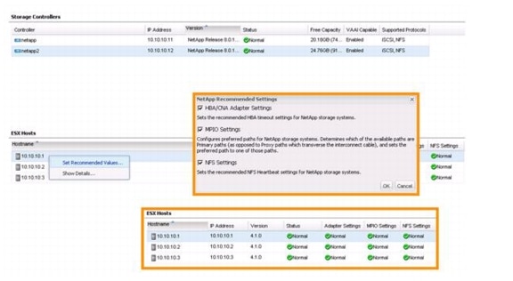
Optimal Storage Settings for ESXi Hosts
Provisioning and Cloning Setup
NetApp OnCommand Deployment Procedure
Manually Add Data Fabric Manager Storage Controllers
Run Diagnostics for Verifying Data Fabric Manager Communication
Configure Additional Operations Manager Alerts
Deploy the NetApp OnCommand Host Package
Set a Shared Lock Directory to Coordinate Mutually Exclusive Activities on Shared Resources
Install NetApp OnCommand Windows PowerShell Cmdlets
Cisco Nexus 1000v Deployment Procedure
Log into Both Cisco Nexus 5548 Switches
Add Packet-Control VLAN to Switch Trunk Ports
Add Packet-Control VLAN to Host Server vNICs
Install the Virtual Ethernet Module (VEM) on Each ESXi Host
Base Configuration of the Primary VSM
Register the Nexus 1000v as a vCenter Plugin
Base Configuration of the Primary VSM
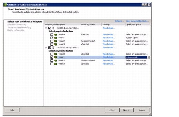
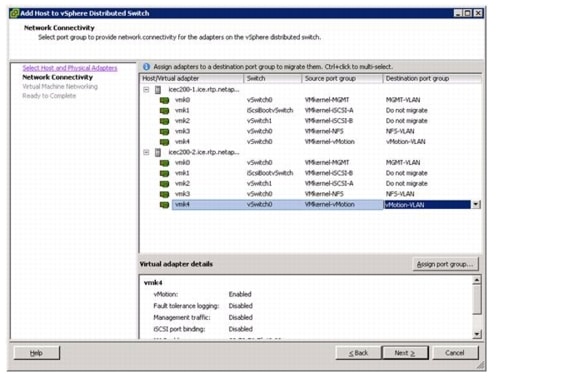
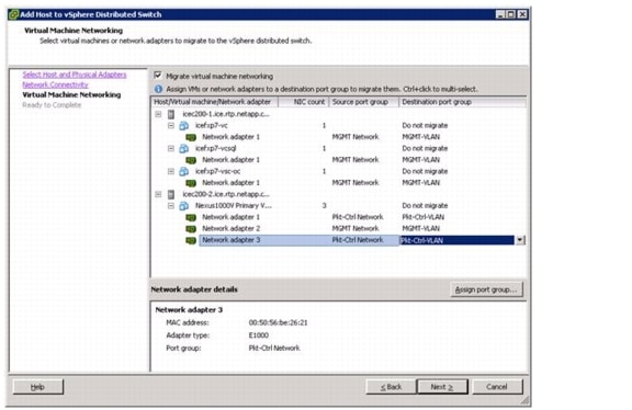
Migrate the ESXi Hosts' Networking to the Nexus 1000v
Base Configuration of the Secondary VSM
Nexus 5548 Reference Configurations
VMware vSphere Built On FlexPod With IP-Based StorageLast Updated: November 29, 2012
Building Architectures to Solve Business Problems
About the Authors
John George, Reference Architect, Infrastructure and Cloud Engineering, NetAppJohn George is a Reference Architect in the NetApp Infrastructure and Cloud Engineering team and is focused on developing, validating, and supporting cloud infrastructure solutions that include NetApp products. Before his current role, he supported and administered Nortel's worldwide training network and VPN infrastructure. John holds a Master's degree in computer engineering from Clemson University.
Ganesh Kameth, Technical Marketing Engineer, NetApp
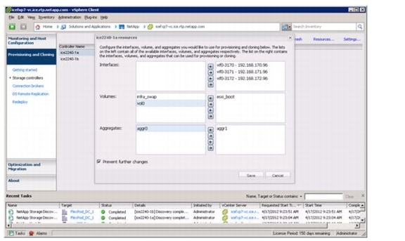
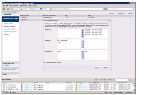
Ganesh Kamath is a Technical Architect in the NetApp TSP solutions engineering team focused on architecting and validating solutions for TSP's based on NetApp products. Ganesh's diverse experiences at NetApp include working as a Technical Marketing Engineer as well as a member of the NetApp Rapid Response Engineering team qualifying specialized solutions for our most demanding customers.
John Kennedy, Technical Leader, CiscoJohn Kennedy is a Technical Marketing Engineer in the Server Access and Virtualization Technology Group. Currently, John is focused on the validation of FlexPod architecture while contributing to future SAVTG products. John spent two years in the Systems Development Unit at Cisco, researching methods of implementing long distance vMotion for use in the Data Center Interconnect Cisco Validated Designs. Previously, John worked at VMware Inc. for eight and a half years as a Senior Systems Engineer supporting channel partners outside the US and serving on the HP Alliance team. He is a VMware Certified Professional on every version of VMware's ESX / ESXi, vCenter, and Virtual Infrastructure including vSphere 5. He has presented at various industry conferences in over 20 countries.Chris Reno, Reference Architect, Infrastructure and Cloud Engineering, NetAppChris Reno is a Reference Architect in the NetApp Infrastructure and Cloud Engineering team and is focused on creating, validating, supporting, and evangelizing solutions based on NetApp products. Chris has his Bachelors of Science degree in International Business and Finance and his Bachelors of Arts degree in Spanish from the University of North Carolina - Wilmington while also holding numerous industry certifications.
Lindsey Street, Systems Architect, Infrastructure and Cloud Engineering, NetAppLindsey Street is a systems architect in the NetApp Infrastructure and Cloud Engineering team. She focuses on the architecture, implementation, compatibility, and security of innovative vendor technologies to develop competitive and high-performance end-to-end cloud solutions for customers. Lindsey started her career in 2006 at Nortel as an interoperability test engineer, testing customer equipment interoperability for certification. Lindsey has her Bachelors of Science degree in Computer Networking and her Master's of Science in Information Security from East Carolina University.
NetApp, the NetApp logo, Go further, faster, AutoSupport, DataFabric, Data ONTAP, FlexClone, FlexPod, and OnCommand are trademarks or registered trademarks of NetApp, Inc. in the United States and/or other countries.
About Cisco Validated Design (CVD) Program
The CVD program consists of systems and solutions designed, tested, and documented to facilitate faster, more reliable, and more predictable customer deployments. For more information visit http://www.cisco.com/go/designzone.
ALL DESIGNS, SPECIFICATIONS, STATEMENTS, INFORMATION, AND RECOMMENDATIONS (COLLECTIVELY, "DESIGNS") IN THIS MANUAL ARE PRESENTED "AS IS," WITH ALL FAULTS. CISCO AND ITS SUPPLIERS DISCLAIM ALL WARRANTIES, INCLUDING, WITHOUT LIMITATION, THE WARRANTY OF MERCHANTABILITY, FITNESS FOR A PARTICULAR PURPOSE AND NONINFRINGEMENT OR ARISING FROM A COURSE OF DEALING, USAGE, OR TRADE PRACTICE. IN NO EVENT SHALL CISCO OR ITS SUPPLIERS BE LIABLE FOR ANY INDIRECT, SPECIAL, CONSEQUENTIAL, OR INCIDENTAL DAMAGES, INCLUDING, WITHOUT LIMITATION, LOST PROFITS OR LOSS OR DAMAGE TO DATA ARISING OUT OF THE USE OR INABILITY TO USE THE DESIGNS, EVEN IF CISCO OR ITS SUPPLIERS HAVE BEEN ADVISED OF THE POSSIBILITY OF SUCH DAMAGES.
THE DESIGNS ARE SUBJECT TO CHANGE WITHOUT NOTICE. USERS ARE SOLELY RESPONSIBLE FOR THEIR APPLICATION OF THE DESIGNS. THE DESIGNS DO NOT CONSTITUTE THE TECHNICAL OR OTHER PROFESSIONAL ADVICE OF CISCO, ITS SUPPLIERS OR PARTNERS. USERS SHOULD CONSULT THEIR OWN TECHNICAL ADVISORS BEFORE IMPLEMENTING THE DESIGNS. RESULTS MAY VARY DEPENDING ON FACTORS NOT TESTED BY CISCO.
The Cisco implementation of TCP header compression is an adaptation of a program developed by the University of California, Berkeley (UCB) as part of UCB's public domain version of the UNIX operating system. All rights reserved. Copyright © 1981, Regents of the University of California.
Cisco and the Cisco Logo are trademarks of Cisco Systems, Inc. and/or its affiliates in the U.S. and other countries. A listing of Cisco's trademarks can be found at http://www.cisco.com/go/trademarks. Third party trademarks mentioned are the property of their respective owners. The use of the word partner does not imply a partnership relationship between Cisco and any other company. (1005R)
Any Internet Protocol (IP) addresses and phone numbers used in this document are not intended to be actual addresses and phone numbers. Any examples, command display output, network topology diagrams, and other figures included in the document are shown for illustrative purposes only. Any use of actual IP addresses or phone numbers in illustrative content is unintentional and coincidental.
© 2012 Cisco Systems, Inc. All rights reserved.
VMware vSphere Built On FlexPod With IP-Based Storage
Overview
Industry trends indicate a vast data center transformation toward shared infrastructures. By leveraging virtualization, enterprise customers have embarked on the journey to the cloud by moving away from application silos and toward shared infrastructure, thereby increasing agility and reducing costs. NetApp and Cisco have partnered to deliver FlexPod, which serves as the foundation for a variety of workloads and enables efficient architectural designs that are based on customer requirements.
Audience
This Cisco Validated Design describes the architecture and deployment procedures of an infrastructure composed of Cisco, NetApp, and VMware virtualization that leverages IP-based storage protocols. The intended audience of this document includes, but is not limited to, sales engineers, field consultants, professional services, IT managers, partner engineers, and customers who want to deploy the core FlexPod architecture.
Architecture
The FlexPod architecture is highly modular or "podlike." Although each customer's FlexPod unit varies in its exact configuration, once a FlexPod unit is built, it can easily be scaled as requirements and demand change. The unit can be scaled both up (adding resources to a FlexPod unit) and out (adding more FlexPod units).
Specifically, FlexPod is a defined set of hardware and software that serves as an integrated foundation for all virtualization solutions. VMware vSphere Built On FlexPod With IP-Based Storage includes NetApp storage, Cisco networking, the Cisco® Unified Computing System™ (Cisco UCS™), and VMware vSphere™ software in a single package. The computing and storage can fit in one data center rack, with the networking residing in a separate rack or deployed according to a customer's data center design. Port density enables the networking components to accommodate multiple configurations of this kind.
One benefit of the FlexPod architecture is the ability to customize or "flex" the environment to suit a customer's requirements. This is why the reference architecture detailed in this document highlights the resiliency, cost benefit, and ease of deployment of an IP-based storage solution. Ethernet storage systems are a steadily increasing source of network traffic, requiring design considerations that maximize the performance of servers to storage systems. This new concept is quite different from a network that caters to thousands of clients and servers connected across LAN and WAN networks. Correct Ethernet storage network designs can achieve the performance of Fibre Channel networks, provided that technologies such as jumbo frames, virtual interfaces (VIFs), virtual LANs (VLANs), IP multipathing (IPMP), Spanning Tree Protocol (STP), port channeling, and multilayer topologies are employed in the architecture of the system.
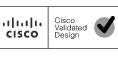
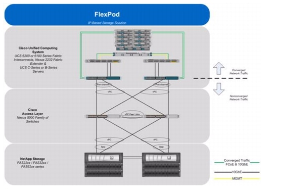
Figure 1 shows the VMware vSphere Built On FlexPod With IP-Based Storage components and the network connections for a configuration with IP-based storage. This design leverages the Cisco Nexus® 5548UP, Cisco Nexus 2232 FEX, Cisco UCS C-Series with the Cisco UCS virtual interface card (VIC), and the NetApp FAS family of storage controllers, which are all deployed to enable iSCSI-booted hosts with file- and block-level access to IP-based datastores. The reference architecture reinforces the "wire-once" strategy, because as additional storage is added to the architecture-either FC, FCoE, or 10GbE-no re-cabling is required from the hosts to the UCS fabric interconnect. An alternate IP-based storage configuration with Cisco UCS B-Series is described in B-Series Deployment Procedure in the Appendix.
Figure 1 VMware vSphere Built On FlexPod With IP-Based Storage Components
The reference configuration includes:
•
Two Cisco Nexus 5548UP switches
•
•
•
•
•
Storage is provided by a NetApp FAS2240-2A (HA configuration in a single chassis). All system and network links feature redundancy, providing end-to-end high availability (HA). For server virtualization, the deployment includes VMware vSphere. Although this is the base design, each of the components can be scaled flexibly to support specific business requirements. For example, more (or different) servers or even blade chassis can be deployed to increase compute capacity, additional disk shelves can be deployed to improve I/O capacity and throughput, and special hardware or software features can be added to introduce new features.
The remainder of this document guides you through the low-level steps for deploying the base architecture, as shown in Figure 1. This includes everything from physical cabling, to compute and storage configuration, to configuring virtualization with VMware vSphere.
FlexPod Benefits
One of the founding design principles of the FlexPod architecture is flexibility. Previous FlexPod architectures have highlighted FCoE- or FC-based storage solutions in addition to showcasing a variety of application workloads. This particular FlexPod architecture is a predesigned configuration that is built on the Cisco Unified Computing System, the Cisco Nexus family of data center switches, NetApp FAS storage components, and VMware virtualization software. FlexPod is a base configuration, but it can scale up for greater performance and capacity, and it can scale out for environments that require consistent, multiple deployments. FlexPod has the flexibility to be sized and optimized to accommodate many different use cases. These use cases can be layered on an infrastructure that is architected based on performance, availability, and cost requirements.
FlexPod is a platform that can address current virtualization needs and simplify the evolution to an IT-as-a-service (ITaaS) infrastructure. The VMware vSphere Built On FlexPod With IP-Based Storage solution can help improve agility and responsiveness, reduce total cost of ownership (TCO), and increase business alignment and focus.
This document focuses on deploying an infrastructure that is capable of supporting VMware vSphere, VMware vCenter™ with NetApp plug-ins, and NetApp OnCommand™ as the foundation for virtualized infrastructure. Additionally, this document details a use case for those who want to design a potentially lower cost solution by leveraging IP storage protocols such as iSCSI, CIFS, and NFS, thereby avoiding the costs and complexities typically incurred with traditional FC SAN architectures. For a detailed study of several practical solutions deployed on FlexPod, refer to the NetApp Technical Report 3884, FlexPod Solutions Guide.
Benefits of Cisco Unified Computing System
Cisco Unified Computing System™ is the first converged data center platform that combines industry-standard, x86-architecture servers with networking and storage access into a single converged system. The system is entirely programmable using unified, model-based management to simplify and speed deployment of enterprise-class applications and services running in bare-metal, virtualized, and cloud computing environments.
The system's x86-architecture rack-mount and blade servers are powered by Intel® Xeon® processors. These industry-standard servers deliver world-record performance to power mission-critical workloads. Cisco servers, combined with a simplified, converged architecture, drive better IT productivity and superior price/performance for lower total cost of ownership (TCO). Building on Cisco's strength in enterprise networking, Cisco's Unified Computing System is integrated with a standards-based, high-bandwidth, low-latency, virtualization-aware unified fabric. The system is wired once to support the desired bandwidth and carries all Internet protocol, storage, inter-process communication, and virtual machine traffic with security isolation, visibility, and control equivalent to physical networks. The system meets the bandwidth demands of today's multicore processors, eliminates costly redundancy, and increases workload agility, reliability, and performance.
Cisco Unified Computing System is designed from the ground up to be programmable and self- integrating. A server's entire hardware stack, ranging from server firmware and settings to network profiles, is configured through model-based management. With Cisco virtual interface cards, even the number and type of I/O interfaces is programmed dynamically, making every server ready to power any workload at any time. With model-based management, administrators manipulate a model of a desired system configuration, associate a model's service profile with hardware resources, and the system configures itself to match the model. This automation speeds provisioning and workload migration with accurate and rapid scalability. The result is increased IT staff productivity, improved compliance, and reduced risk of failures due to inconsistent configurations.
Cisco Fabric Extender technology reduces the number of system components to purchase, configure, manage, and maintain by condensing three network layers into one. This represents a radical simplification over traditional systems, reducing capital and operating costs while increasing business agility, simplifying and speeding deployment, and improving performance.
Cisco Unified Computing System helps organizations go beyond efficiency: it helps them become more effective through technologies that breed simplicity rather than complexity. The result is flexible, agile, high-performance, self-integrating information technology, reduced staff costs with increased uptime through automation, and more rapid return on investment.
This reference architecture highlights the use of the Cisco UCS C200-M2 server, the Cisco UCS 6248UP, and the Nexus 2232 FEX to provide a resilient server platform balancing simplicity, performance and density for production-level virtualization. Also highlighted in this architecture, is the use of Cisco UCS service profiles that enable iSCSI boot of the native operating system. Coupling service profiles with unified storage delivers on demand stateless computing resources in a highly scalable architecture.
Recommended support documents include:
•
•
•
Benefits of Cisco Nexus 5548UP
The Cisco Nexus 5548UP Switch delivers innovative architectural flexibility, infrastructure simplicity, and business agility, with support for networking standards. For traditional, virtualized, unified, and high-performance computing (HPC) environments, it offers a long list of IT and business advantages, including:
Architectural Flexibility
•
•
•
•
•
•
Infrastructure Simplicity
•
•
•
•
•
Business Agility
•
•
•
Specifications at-a Glance
•
•
•
•
This reference architecture highlights the use of the Cisco Nexus 5548UP. As mentioned, this platform is capable of serving as the foundation for wire-once, unified fabric architectures. This document provides guidance for an architecture capable of delivering IP protocols including iSCSI, CIFS, and NFS. Ethernet architectures yield lower TCO through their simplicity and lack of need for FC SAN trained professionals while requiring fewer licenses to deliver the functionality associated with enterprise class solutions.
Recommended support documents include:
•
Benefits of the NetApp FAS Family of Storage Controllers
The NetApp Unified Storage Architecture offers customers an agile and scalable storage platform. All NetApp storage systems use the Data ONTAP® operating system to provide SAN (FCoE, FC, iSCSI), NAS (CIFS, NFS), and primary and secondary storage in a single unified platform so that all virtual desktop data components can be hosted on the same storage array.
A single process for activities such as installation, provisioning, mirroring, backup, and upgrading is used throughout the entire product line, from the entry level to enterprise-class controllers. Having a single set of software and processes simplifies even the most complex enterprise data management challenges. Unifying storage and data management software and processes streamlines data ownership, enables companies to adapt to their changing business needs without interruption, and reduces total cost of ownership.
This reference architecture focuses on the use case of leveraging IP-based storage to solve customers' challenges and to meet their needs in the data center. Specifically, this entails iSCSI boot of UCS hosts, provisioning of VM data stores by using NFS, and application access through iSCSI, CIFS, or NFS, all while leveraging NetApp unified storage.
In a shared infrastructure, the availability and performance of the storage infrastructure are critical because storage outages and performance issues can affect thousands of users. The storage architecture must provide a high level of availability and performance. For detailed documentation about best practices, NetApp and its technology partners have developed a variety of best practice documents.
This reference architecture highlights the use of the NetApp FAS2000 product line, specifically the FAS2240-2A with the 10GbE mezzanine card and SAS storage. Available to support multiple protocols while allowing the customer to start smart, at a lower price point, the FAS2240-2 is an affordable and powerful choice for delivering shared infrastructure.
Recommended support documents include:
•
•
•
•
•
•
•
Benefits of OnCommand Unified Manager Software
NetApp OnCommand management software delivers efficiency savings by unifying storage operations, provisioning, and protection for both physical and virtual resources. The key product benefits that create this value include:
•
•
•
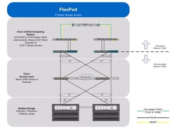
OnCommand gives you visibility across your storage environment by continuously monitoring and analyzing its health. You get a view of what is deployed and how it is being used, enabling you to improve your storage capacity utilization and increase the productivity and efficiency of your IT administrators. And this unified dashboard gives at-a-glance status and metrics, making it far more efficient than having to use multiple resource management tools.
Figure 2 OnCommand Architecture
OnCommand Host Package
You can discover, manage, and protect virtual objects after installing the NetApp OnCommand Host Package software. The components that make up the OnCommand Host Package are:
•
•
•
Management tasks performed in the virtual environment by using the OnCommand console include:
•
•
•
•
•
•
•
Storage Service Catalog
The Storage Service Catalog, a component of OnCommand, is a key NetApp differentiator for service automation. It lets you integrate storage provisioning policies, data protection policies, and storage resource pools into a single service offering that administrators can choose when provisioning storage. This automates much of the provisioning process, and it also automates a variety of storage management tasks associated with the policies.
The Storage Service Catalog provides a layer of abstraction between the storage consumer and the details of the storage configuration, creating "storage as a service." The service levels defined with the Storage Service Catalog automatically specify and map policies to the attributes of your pooled storage infrastructure. This higher level of abstraction between service levels and physical storage lets you eliminate complex, manual work, encapsulating storage and operational processes together for optimal, flexible, and dynamic allocation of storage.
The service catalog approach also incorporates the use of open APIs into other management suites, which leads to a strong ecosystem integration.
FlexPod Management Solutions
The FlexPod platform open APIs offer easy integration with a broad range of management tools. NetApp and Cisco work with trusted partners to provide a variety of management solutions.
Products designated as Validated FlexPod Management Solutions must pass extensive testing in Cisco and NetApp labs against a broad set of functional and design requirements. Validated solutions for automation and orchestration provide unified, turnkey functionality. Now you can deploy IT services in minutes instead of weeks by reducing complex processes that normally require multiple administrators to repeatable workflows that are easily adaptable. The following list names the current vendors for these solutions:
Note
•
–
–
•
–
–
•
–
–
•
–
–
Benefits of VMware vSphere with the NetApp Virtual Storage Console
VMware vSphere, coupled with the NetApp Virtual Storage Console (VSC), serves as the foundation for VMware virtualized infrastructures. vSphere 5.0 offers significant enhancements that can be employed to solve real customer problems. Virtualization reduces costs and maximizes IT efficiency, increases application availability and control, and empowers IT organizations with choice. VMware vSphere delivers these benefits as the trusted platform for virtualization, as demonstrated by their contingent of more than 300,000 customers worldwide.
VMware vCenter Server is the best way to manage and leverage the power of virtualization. A vCenter domain manages and provisions resources for all the ESX hosts in the given data center. The ability to license various features in vCenter at differing price points allows customers to choose the package that best serves their infrastructure needs.
The VSC is a vCenter plug-in that provides end-to-end virtual machine (VM) management and awareness for VMware vSphere environments running on top of NetApp storage. The following core capabilities make up the plug-in:
•
•
•
•
Because the VSC is a vCenter plug-in, all vSphere clients that connect to vCenter can access VSC. This availability is different from a client-side plug-in that must be installed on every vSphere client.
Software Revisions
It is important to note the software versions used in this document. Table 1 details the software revisions used throughout this document.
Table 1 Software Revisions
Configuration Guidelines
This document provides details for configuring a fully redundant, highly available configuration for a FlexPod unit with IP-based storage. Therefore, reference is made to which component is being configured with each step, either A or B. For example, controller A and controller B are used to identify the two NetApp storage controllers that are provisioned with this document, and Nexus A and Nexus B identify the pair of Cisco Nexus switches that are configured. The Cisco UCS fabric interconnects are similarly configured. Additionally, this document details steps for provisioning multiple Cisco UCS hosts, and these are identified sequentially: VM-Host-Infra-01, VM-Host-Infra-02, and so on. Finally, to indicate that you should include information pertinent to your environment in a given step, <text> appears as part of the command structure. See the following example for the vlan create command:
controller A> vlan create
Usage:
vlan create [-g {on|off}] <ifname> <vlanid_list>
vlan add <ifname> <vlanid_list>
vlan delete -q <ifname> [<vlanid_list>]
vlan modify -g {on|off} <ifname>
vlan stat <ifname> [<vlanid_list>]
Example:
controller A> vlan create vif0 <management VLAN ID>
This document is intended to enable you to fully configure the customer environment. In this process, various steps require you to insert customer-specific naming conventions, IP addresses, and VLAN schemes, as well as to record appropriate MAC addresses. Table 2 details the list of VLANs necessary for deployment as outlined in this guide. The VM-Mgmt VLAN is used for management interfaces of the VMware vSphere hosts. Table 3 lists the configuration variables that are used throughout this document. This table can be completed based on the specific site variables and leveraged as one reads the document configuration steps..
Note
Table 2 Necessary VLANs
Table 3 Configuration Variables
Note
•
•
•
•
•
•
•
For all host names except the virtual machine host names, the IP addresses must be preconfigured in the local DNS server. Additionally, the NFS IP addresses of the NetApp storage systems are used to monitor the storage systems from OnCommand DataFabric Manager. In this validation, a management host name was assigned to each storage controller (that is, ice2240-1a-m) and provisioned in DNS. A host name was also assigned for each controller in the NFS VLAN (that is, ice2240-1a) and provisioned in DNS. This NFS VLAN host name was then used when the storage system was added to OnCommand DataFabric Manager.
Deployment
This document describes the steps to deploy base infrastructure components as well as to provision VMware vSphere as the foundation for virtualized workloads. When you finish these deployment steps, you will be prepared to provision applications on top of a VMware virtualized infrastructure. The outlined procedure contains the following steps:
•
•
•
•
•
•
•
•
•
•
•
•
•
•
The VMware vSphere Built On FlexPod With IP-Based Storage architecture is flexible; therefore the configuration detailed in this section can vary for customer implementations, depending on specific requirements. Although customer implementations can deviate from the following information, the best practices, features, and configurations described in this section should be used as a reference for building a customized VMware vSphere Built On FlexPod With IP-Based Storage built on FlexPod solution.
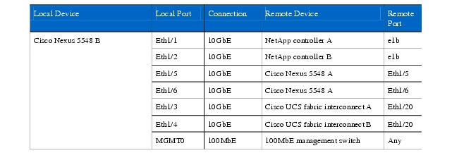
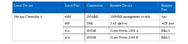
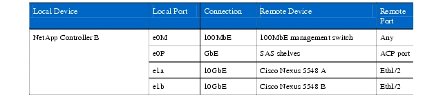
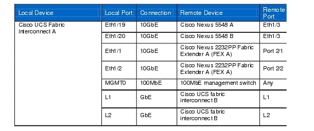
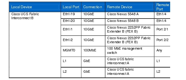
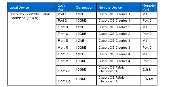
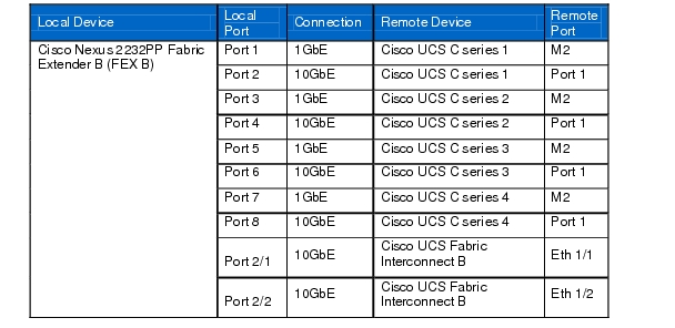
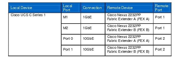
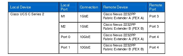
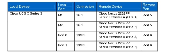
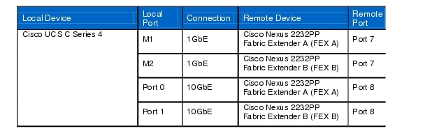
Cabling Information
The information in this section is provided as a reference for cabling the physical equipment in a FlexPod environment. To simplify cabling requirements, the tables include both local and remote device and port locations.
The tables in this section contain details for the prescribed and supported configuration of the NetApp FAS2240-2A running Data ONTAP 8.1. This configuration leverages a dual-port 10GbE adapter and the onboard SAS disk shelves with no additional external storage. For any modifications of this prescribed architecture, consult the NetApp Interoperability Matrix Tool (IMT).
This document assumes that out-of-band management ports are plugged into an existing management infrastructure at the deployment site.
Be sure to follow the cabling directions in this section. Failure to do so will result in necessary changes to the deployment procedures that follow because specific port locations are mentioned.
It is possible to order a FAS2240-2A system in a different configuration from what is prescribed in the tables in this section. Before starting, be sure that the configuration matches the descriptions in the tables and diagrams in this section.
Figure 3 shows a FlexPod cabling diagram. The labels indicate connections to end points rather than port numbers on the physical device. For example, connection 1 is an FCoE target port connected from NetApp controller A to Nexus 5548 A. SAS connections 23, 24, 25, and 26 as well as ACP connections 27 and 28 should be connected to the NetApp storage controller and disk shelves according to best practices for the specific storage controller and disk shelf quantity.
Note
Figure 3 FlexPod Cabling Diagram
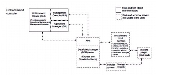
Table 4 Cisco Nexus 5548 A Ethernet Cabling Information
Note
Table 5 Cisco Nexus 5548 B Ethernet Cabling Information
Note
Table 6 NetApp Controller A Ethernet Cabling Information
Table 7 NetApp Controller B Ethernet Cabling Information
Table 8 Cisco UCS Fabric Interconnect A Ethernet Cabling Information
Table 9 Cisco UCS Fabric Interconnect B Ethernet Cabling Information
Table 10 Cisco Nexus 2232PP Fabric Extender A (FEX A)
Table 11 Cisco Nexus 2232PP Fabric Extender B (FEX B)
Table 12 Cisco UCS C Series 1
Table 13 Cisco UCS C Series 2
Table 14 Cisco UCS C Series 3
Table 15 Cisco UCS C Series 4
NetApp FAS2240-2 Deployment Procedure: Part 1
This section provides a detailed procedure for configuring the NetApp FAS2240-2 for use in a VMware vSphere Built On FlexPod With IP-Based Storage solution. These steps should be followed precisely. Failure to do so could result in an improper configuration.
Note
Assign Controller Disk Ownership
These steps provide details for assigning disk ownership and disk initialization and verification.
Note
Note
Controller A
1.
2.
3.
4.
Note
5.
6.
7.
8.
9.
10.
11.
12.
13.
Note
Controller B
1.
2.
3.
4.
Note
5.
6.
7.
8.
9.
10.
11.
12.
13.
Note
Set Up Data ONTAP 8.1
These steps provide details for setting up Data ONTAP 8.1.
Controller A and Controller B
1.
2.
3.
4.
5.
6.
7.
8.
9.
10.
11.
12.
13.
14.
15.
16.
17.
18.
19.
20.
21.
22.
23.
24.
25.
26.
27.
28.
29.
30.
31.
32.
33.
34.
35.
36.
37.
38.
39.
40.
41.
42.
43.
44.
Note
Note
45.
46.
47.
Install Data ONTAP to Onboard Flash Storage
The following steps describe installing Data ONTAP to the onboard flash storage.
Controller A and Controller B
1.
http://192.168.175.5/81_q_image.tgz2.
Harden Storage System Logins and Security
The following steps describe hardening the storage system logins and security.
Controller A and Controller B
1.
2.
3.
4.
5.
6.
7.
8.
9.
10.
11.
12.
13.
14.
15.
16.
Install the Required Licenses
The following steps provide details about storage licenses that are used to enable features in this reference architecture. A variety of licenses come installed with the Data ONTAP 8.1 software.
Note
•
•
•
•
Controller A and Controller B
1.
2.
3.
4.
Enable Licensed Features
The following steps provide details for enabling licensed features.
Controller A and Controller B
1.
2.
Enable Active-Active Controller Configuration Between Two Storage Systems
This step provides details for enabling active-active controller configuration between the two storage systems.
Controller A only
1.
Start iSCSI
This step provides details for enabling the iSCSI protocol.
Controller A and Controller B
1.
Set Up Storage System NTP Time Synchronization and CDP Enablement
The following steps provide details for setting up storage system NTP time synchronization and enabling Cisco Discovery Protocol (CDP).
Controller A and Controller B
1.
2.
3.
4.
5.
Create Data Aggregate aggr1
The following step provides details for creating the data aggregate aggr1.
Note
Controller A
1.
Controller B
1.
Create an SNMP Requests Role and Assign SNMP Login Privileges
This step provides details for creating the SNMP request role and assigning SNMP login privileges to it.
Controller A and Controller B
1.
Create an SNMP Management Group and Assign an SNMP Request Role
This step provides details for creating an SNMP management group and assigning an SNMP request role to it.
Controller A and Controller B
1.
Create an SNMP User and Assign It to an SNMP Management Group
This step provides details for creating an SNMP user and assigning it to an SNMP management group.
Controller A and Controller B
1.
Note
Set Up SNMP v1 Communities on Storage Controllers
These steps provide details for setting up SNMP v1 communities on the storage controllers so that OnCommand System Manager can be used.
Controller A and Controller B
1.
2.
Set Up SNMP Contact Information for Each Storage Controller
This step provides details for setting SNMP contact information for each of the storage controllers.
Controller A and Controller B
1.
Set SNMP Location Information for Each Storage Controller
This step provides details for setting SNMP location information for each of the storage controllers.
Controller A and Controller B
1.
Reinitialize SNMP on Storage Controllers
This step provides details for reinitializing SNMP on the storage controllers.
Controller A and Controller B
1.
Initialize NDMP on the Storage Controllers
This step provides details for initializing NDMP.
Controller A and Controller B
1.
Set 10GbE Flow Control and Add VLAN Interfaces
These steps provide details for adding VLAN interfaces on the storage controllers.
Controller A
1.
2.
3.
4.
5.
6.
7.
8.
9.
10.
11.
12.
13.
14.
15.
16.
17.
Controller B
1.
2.
3.
4.
5.
6.
7.
8.
9.
10.
11.
12.
13.
14.
15.
16.
17.
Add Infrastructure Volumes
The following steps describe adding volumes on the storage controller for SAN boot of the Cisco UCS hosts as well as virtual machine provisioning.
Note
Controller A
1.
2.
3.
4.
5.
Controller B
1.
2.
Export NFS Infrastructure Volumes to ESXi Servers
These steps provide details for setting up NFS exports of the infrastructure volumes to the VMware ESXi servers.
Controller A
1.
2.
Controller B
1.
2.
Cisco Nexus 5548 Deployment Procedure
The following section provides a detailed procedure for configuring the Cisco Nexus 5548 switches for use in a FlexPod environment. Follow these steps precisely because failure to do so could result in an improper configuration.
Note
Set up Initial Cisco Nexus 5548 Switch
These steps provide details for the initial Cisco Nexus 5548 Switch setup.
Cisco Nexus 5548 A
On initial boot and connection to the serial or console port of the switch, the NX-OS setup should automatically start.
1.
2.
3.
4.
5.
6.
7.
8.
9.
10.
11.
12.
13.
14.
15.
16.
17.
18.
19.
20.
21.
22.
23.
24.
25.
Cisco Nexus 5548 B
On initial boot and connection to the serial or console port of the switch, the NX-OS setup should automatically start.
1.
2.
3.
4.
5.
6.
7.
8.
9.
10.
11.
12.
13.
14.
15.
16.
17.
18.
19.
20.
21.
22.
23.
24.
25.
Enable Appropriate Cisco Nexus Features
These steps provide details for enabling the appropriate Cisco Nexus features.
Nexus A and Nexus B
1.
2.
3.
Set Global Configurations
These steps provide details for setting global configurations.
Nexus A and Nexus B
1.
2.
3.
4.
5.
6.
7.
8.
9.
10.
11.
12.
Create Necessary VLANs
These steps provide details for creating the necessary VLANs.
Nexus A and Nexus B
1.
2.
3.
4.
5.
6.
7.
8.
9.
10.
11.
12.
13.
14.
15.
16.
17.
18.
19.
20.
21.
Add Individual Port Descriptions for Troubleshooting
These steps provide details for adding individual port descriptions for troubleshooting activity and verification.
Cisco Nexus 5548 A
1.
2.
3.
4.
5.
6.
7.
8.
9.
10.
11.
12.
13.
14.
15.
16.
17.
18.
Cisco Nexus 5548 B
1.
2.
3.
4.
5.
6.
7.
8.
9.
10.
11.
12.
13.
14.
15.
16.
17.
18.
Create Necessary PortChannels
These steps provide details for creating the necessary PortChannels between devices.
Cisco Nexus 5548 A
1.
2.
3.
4.
5.
6.
7.
8.
9.
10.
11.
12.
13.
14.
15.
16.
17.
18.
19.
20.
21.
22.
23.
24.
25.
26.
27.
28.
29.
30.
31.
32.
33.
34.
35.
36.
Cisco Nexus 5548 B
1.
2.
3.
4.
5.
6.
7.
8.
9.
10.
11.
12.
13.
14.
15.
16.
17.
18.
19.
20.
21.
22.
23.
24.
25.
26.
27.
28.
29.
30.
31.
32.
33.
34.
35.
36.
Add PortChannel Configurations
These steps provide details for adding PortChannel configurations.
Cisco Nexus 5548 A
1.
2.
3.
4.
5.
6.
7.
8.
9.
10.
11.
12.
13.
14.
15.
16.
17.
18.
19.
20.
21.
22.
23.
24.
25.
26.
27.
28.
29.
30.
31.
32.
33.
34.
35.
36.
Cisco Nexus 5548 B
1.
2.
3.
4.
5.
6.
7.
8.
9.
10.
11.
12.
13.
14.
15.
16.
17.
18.
19.
20.
21.
22.
23.
24.
25.
26.
27.
28.
29.
30.
31.
32.
33.
34.
35.
36.
Configure Virtual PortChannels
These steps provide details for configuring virtual PortChannels (vPCs).
Cisco Nexus 5548 A
1.
2.
3.
4.
5.
6.
7.
8.
9.
10.
11.
12.
13.
14.
15.
16.
17.
18.
19.
20.
Cisco Nexus 5548 B
1.
2.
3.
4.
5.
6.
7.
8.
9.
10.
11.
12.
13.
14.
15.
16.
17.
18.
19.
20.
Uplink Into Existing Network Infrastructure
Depending on the available network infrastructure, several methods and features can be used to uplink the FlexPod environment. If an existing Cisco Nexus environment is present, it is recommended to use virtual port channels to uplink the Cisco Nexus 5548 switches included in the FlexPod environment into the infrastructure. The previously described procedures can be used to create an uplink vPC to the existing environment. Make sure to type copy run start to save the configuration on each switch once configuration is completed.
Cisco Unified Computing System Deployment Procedure
The following section provides a detailed procedure for configuring the Cisco Unified Computing System for use in a FlexPod environment. These steps should be followed precisely because a failure to do so could result in an improper configuration.
Perform Initial Setup of Cisco UCS C-Series Servers
These steps provide details for initial setup of the Cisco UCS C-Series Servers. It is important to get the systems to a known state with the appropriate firmware package.
All C-Series Servers
1.
2.
3.
4.
5.
6.
7.
8.
9.
10.
11.
12.
13.
14.
15.
16.
17.
18.
Perform Initial Setup of the Cisco UCS 6248 Fabric Interconnects
These steps provide details for initial setup of the Cisco UCS 6248 fabric Interconnects
Cisco UCS 6248 A
1.
2.
3.
4.
5.
6.
7.
8.
9.
10.
11.
12.
13.
14.
15.
16.
17.
18.
19.
20.
Cisco UCS 6248 B
1.
2.
3.
4.
5.
6.
7.
Log Into Cisco UCS Manager
Cisco UCS Manager
These steps provide details for logging into the Cisco UCS environment.
1.
2.
3.
4.
Upgrade Cisco UCS Manager Software to Version 2.0(2m)
This document assumes the use of Cisco UCS Manager 2.0(2m). Refer to Upgrading Between Cisco UCS 2.0 Releases to upgrade the Cisco UCS Manager software and Cisco UCS 6248 Fabric Interconnect software to version 2.0(2m). Also, make sure that the Cisco UCS C-Series version 2.0 (2m) software bundle is loaded on the fabric interconnects.
Add a Block of IP Addresses for KVM Access
These steps provide details for creating a block of KVM IP addresses for server access in the Cisco UCS environment. This block of IP addresses should be in the same subnet as the management IP addresses for the Cisco UCS Manager.
Cisco UCS Manager
1.
2.
3.
4.
5.
6.
7.
Synchronize Cisco UCS to NTP
These steps provide details for synchronizing the Cisco UCS environment to the NTP server.
Cisco UCS Manager
1.
2.
3.
4.
5.
6.
7.
Edit the Chassis Discovery Policy
These steps provide details for modifying the chassis discovery policy. Setting the discovery policy now will simplify the addition of future Cisco B-Series UCS Chassis and additional fabric extenders for further Cisco UCS C-Series connectivity.
Cisco UCS Manager
1.
2.
3.
4.
5.
6.
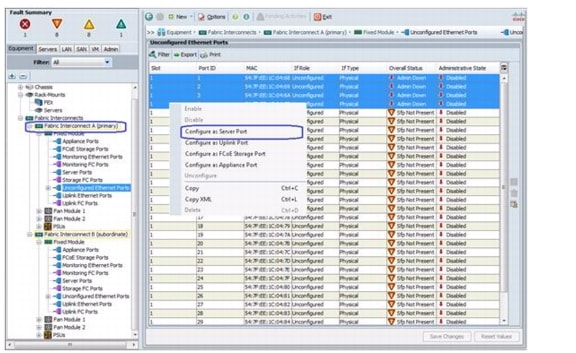
Enable Server and Uplink Ports
These steps provide details for enabling server and uplinks ports.
Cisco UCS Manager
1.
2.
3.
4.
5.
6.
7.
8.
9.
10.
11.
12.
13.
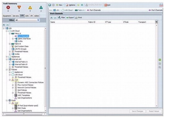
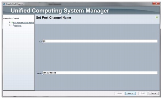
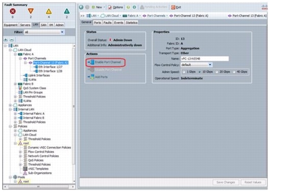
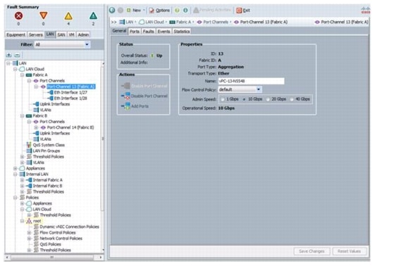
Create Uplink PortChannels to the Cisco Nexus 5548 Switches
These steps provide details for configuring the necessary PortChannels out of the Cisco UCS environment.
Cisco UCS Manager
1.
Note
2.
3.
4.
5.
6.
7.
8.
9.
10.
11.
12.
13.
14.
15.
16.
17.
18.
19.
20.
21.
22.
23.
24.
25.
26.
27.
28.
29.
30.
31.
Create an Organization
These steps provide details for configuring an organization in the Cisco UCS environment. Organizations are used as a means to organize and restrict access to various groups within the IT organization, thereby enabling multi-tenancy of the compute resources. This document does not assume the use of Organizations, however the necessary steps are included below.
Cisco UCS Manager
1.
2.
3.
4.
5.
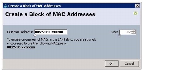
Create MAC Address Pools
These steps provide details for configuring the necessary MAC address pools for the Cisco UCS environment.
Cisco UCS Manager
1.
2.
Note
3.
4.
5.
6.
7.
8.
9.
10.
11.
12.
13.
14.
15.
16.
17.
18.
19.
20.
21.
22.
23.
24.
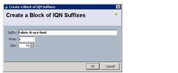
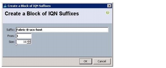
Create IQN Pools for iSCSI Boot
These steps provide details for configuring the necessary IQN pools for the Cisco UCS environment.
Cisco UCS Manager
1.
2.
Note
3.
4.
5.
6.
7.
8.
9.
10.
11.
12.
13.
14.
15.
16.
17.
18.
19.
20.
21.
22.
23.
24.
25.
26.
27.
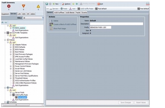
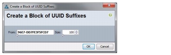
Create UUID Suffix Pool
These steps provide details for configuring the necessary UUID suffix pool for the Cisco UCS environment.
Cisco UCS Manager
1.
2.
3.
4.
5.
6.
7.
8.
9.
10.
11.
12.
13.
14.
Create Server Pool
These steps provide details for configuring the necessary server pool for the Cisco UCS environment.
Cisco UCS Manager
1.
2.
3.
4.
5.
6.
7.
8.
9.
10.
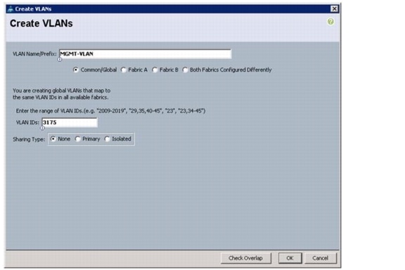
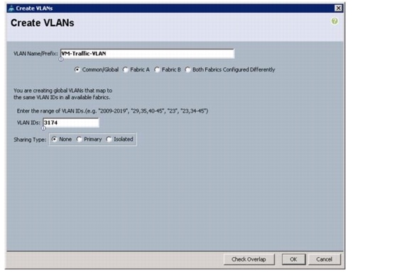
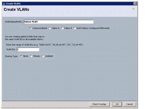
Create VLANs
These steps provide details for configuring the necessary VLANs for the Cisco UCS environment.
Cisco UCS Manager
1.
Note
2.
3.
4.
5.
6.
7.
8.
9.
10.
11.
12.
13.
14.
15.
16.
17.
18.
19.
20.
21.
22.
23.
24.
25.
26.
27.
28.
29.
30.
31.
32.
33.
34.
35.
36.
37.
38.
39.
40.
41.
42.
43.
44.
45.
46.
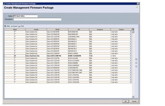
Create a Firmware Management Package
These steps provide details for a firmware management policy for the Cisco UCS environment.
Cisco UCS Manager
1.
2.
3.
4.
5.
6.
7.
8.
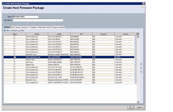
Create Host Firmware Package Policy
These steps provide details for creating a firmware management policy for a given server configuration in the Cisco UCS environment. Firmware management policies allow the administrator to select the corresponding packages for a given server configuration. These often include adapter, BIOS, board controller, FC adapters, HBA option ROM, and storage controller properties.
Cisco UCS Manager
1.
2.
3.
4.
5.
6.
7.
8.
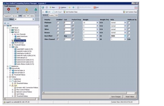
Set Jumbo Frames in Cisco UCS Fabric
These steps provide details for setting Jumbo frames and enabling the quality of server in the Cisco UCS Fabric.
Cisco UCS Manager
1.
2.
3.
4.
5.
6.
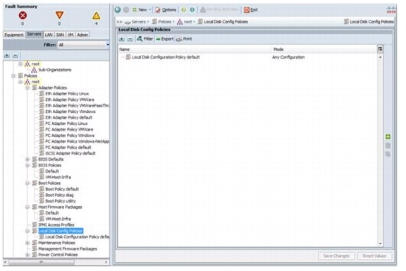
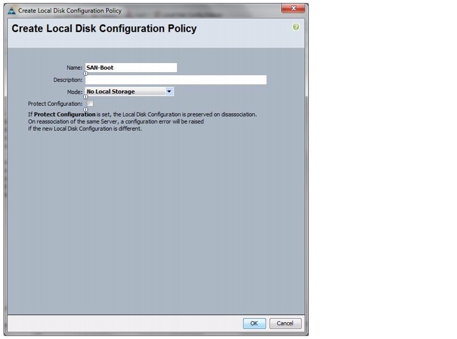
Create a Local Disk Configuration Policy
These steps provide details for creating a local disk configuration for the Cisco UCS environment, which is necessary if the servers in question do not have a local disk.
Note
Cisco UCS Manager
1.
2.
3.
4.
5.
6.
7.
8.
9.
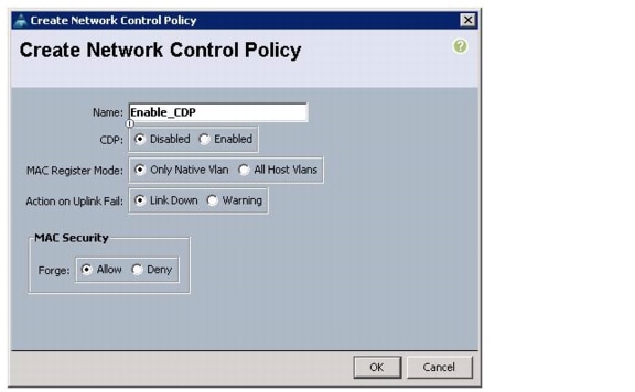
Create a Network Control Policy for Cisco Discovery Protocol (CDP)
These steps provide details for creating a network control policy that enables CDP on virtual network ports.
Cisco UCS Manager
1.
2.
3.
4.
5.
6.
7.
8.
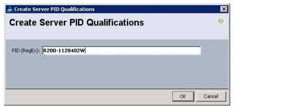
Create a Server Pool Qualification Policy
These steps provide details for creating a server pool qualification policy for the Cisco UCS environment.
Cisco UCS Manager
1.
2.
3.
4.
5.
6.
7.
8.
9.
10.
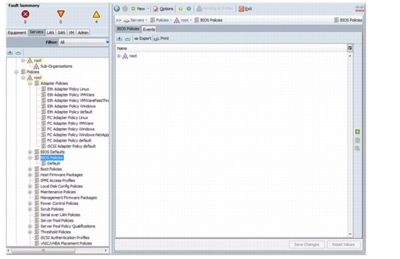
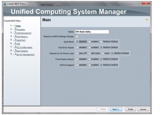
Create a Server BIOS Policy
These steps provide details for creating a server BIOS policy for the Cisco UCS environment.
Cisco UCS Manager
1.
2.
3.
4.
5.
6.
7.
8.
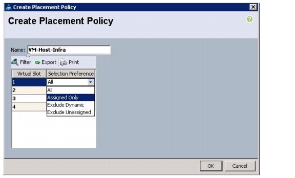
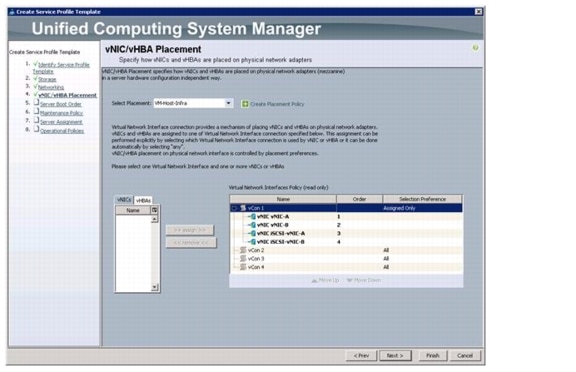
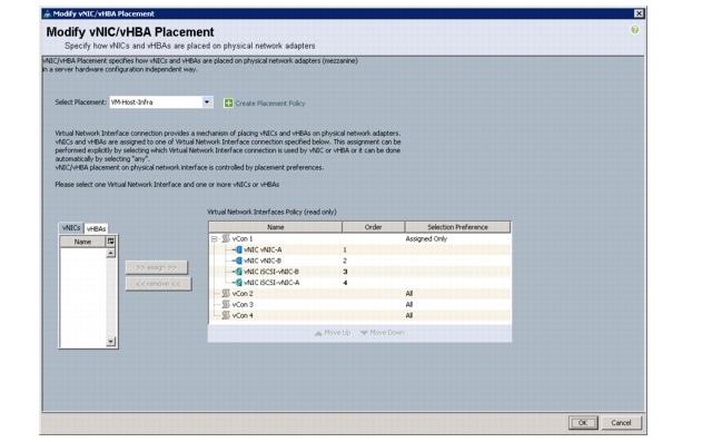
Create vNIC Placement Policy for Virtual Machine Infrastructure Hosts
These steps provide details for creating a vNIC placement policy for infrastructure hosts.
Cisco UCS Manager
1.
2.
3.
4.
5.
6.
7.
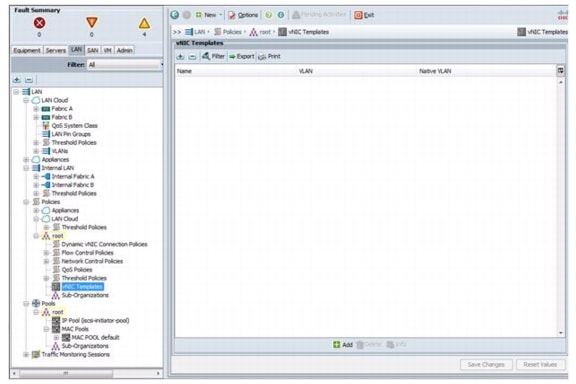
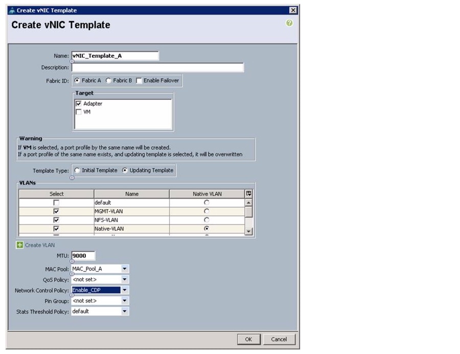
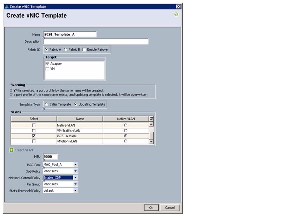
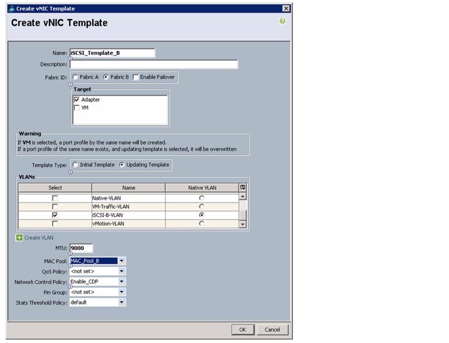
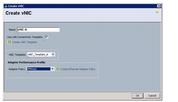
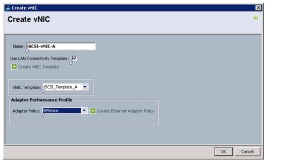
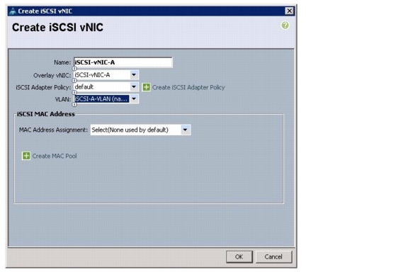
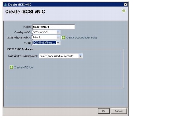
Create vNIC Templates
These steps provide details for creating multiple vNIC templates for the Cisco UCS environment.
Cisco UCS Manager
1.
2.
3.
4.
5.
6.
7.
8.
9.
10.
11.
12.
13.
14.
15.
16.
17.
18.
19.
20.
21.
22.
23.
24.
25.
26.
27.
28.
29.
30.
31.
32.
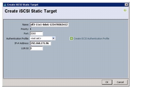
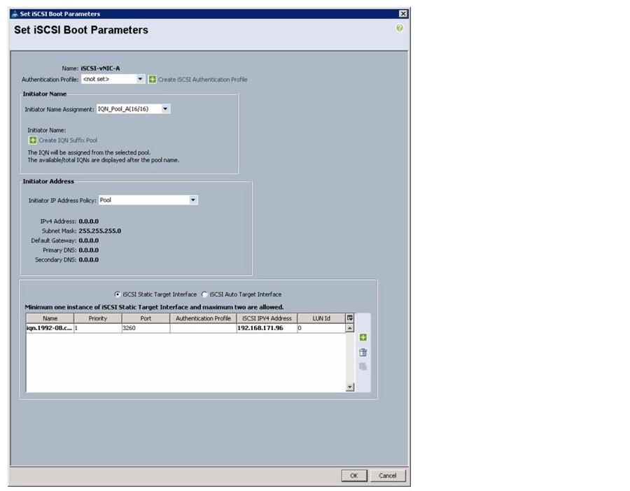
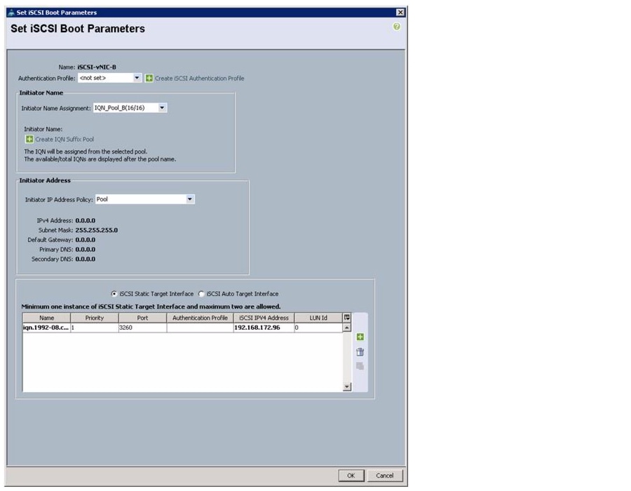
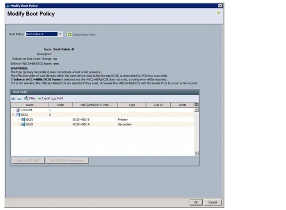
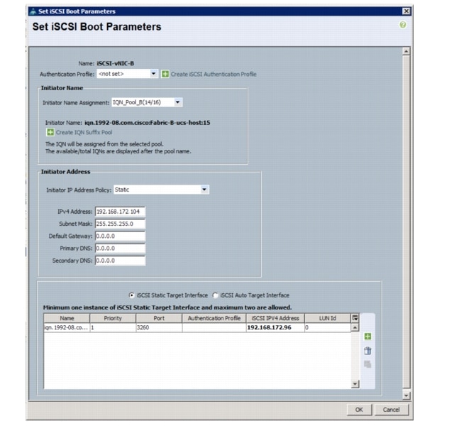
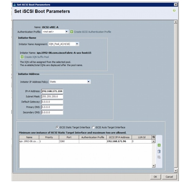
Create Boot Policies
These steps provide details for creating two iSCSI boot policies for the Cisco UCS environment. The first policy will configure the primary boot target to be controller A through Fabric A and the second boot policy primary target will be controller A through Fabric B.
Cisco UCS Manager
1.
2.
3.
4.
5.
6.
7.
8.
9.
10.
11.
12.
13.
14.
15.
16.
17.
18.
19.
20.
21.
22.
23.
24.
25.
26.
27.
28.
29.
30.
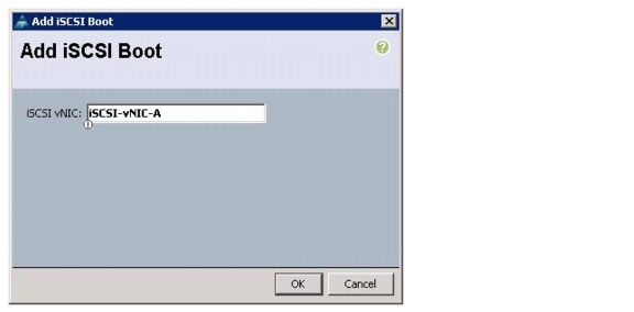
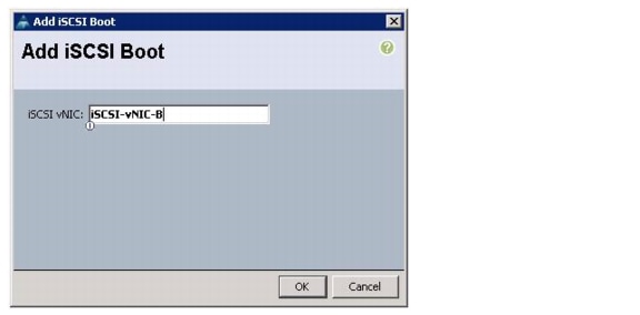
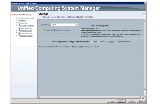
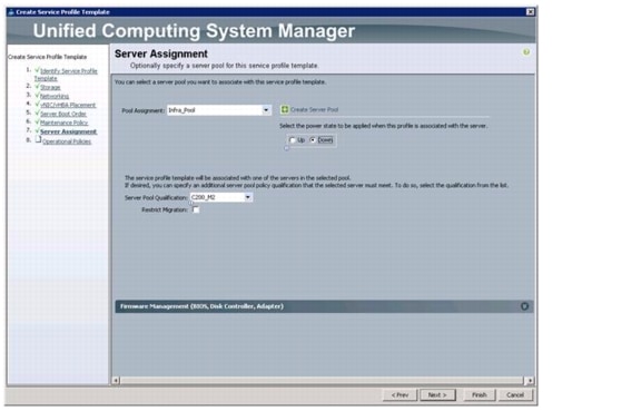
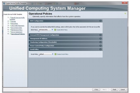
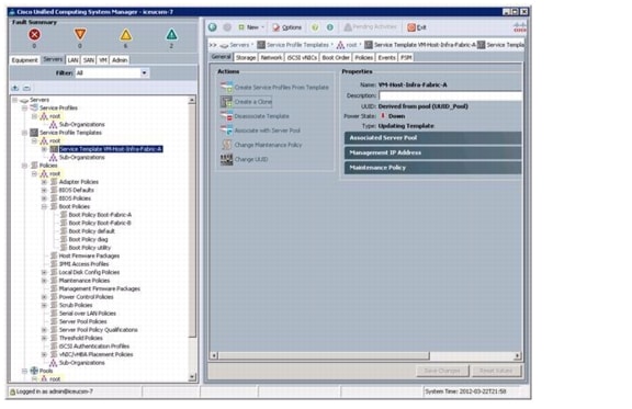
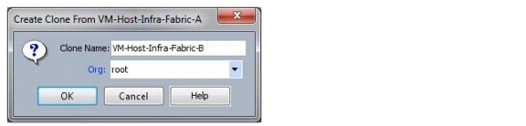
Create Service Profiles
This section details the creation of two service profiles: one for fabric A boot and one for fabric B boot. The first profile is created and then cloned and modified for the second host.
Cisco UCS Manager
1.
2.
3.
4.
5.
a.
b.
c.
6.
a.
b.
c.
7.
a.
b.
c.
d.
e.
f.
g.
h.
i.
j.
k.
l.
m.
n.
o.
p.
q.
r.
s.
t.
u.
v.
w.
x.
y.
z.
aa.
ab.
ac.
ad.
ae.
af.
ag.
ah.
ai.
aj.
ak.
al.
am.
an.
ao.
ap.
aq.
8.
a.
b.
–
–
–
–
c.
d.
9.
a.
b.
c.
d.
e.
f.
g.
h.
i.
j.
k.
l.
m.
n.
o.
p.
q.
r.
s.
t.
u.
v.
w.
x.
y.
10.
a.
b.
11.
a.
b.
c.
d.
e.
f.
12.
a.
b.
c.
13.
14.
15.
16.
17.
18.
19.
20.
21.
22.
23.
24.
25.
26.
27.
28.
29.
30.
31.
32.
33.
34.
35.
36.
Add More Servers to the FlexPod Unit
Add server pools, service profile templates, and service profiles in the respective organizations to add more servers to the FlexPod unit. All other pools and policies are at the root level and can be shared among the organizations.
Gather Necessary Information
After the Cisco UCS service profiles have been created (as detailed in the previous steps), the infrastructure blades in the environment each have a unique configuration. To proceed with the FlexPod deployment, specific information must be gathered from each Cisco UCS server. Insert the required information in the tables below.
Table 16 Cisco UCS Server Information
VM-Host-Infra-01
VM-Host-Infra-02
To gather the information in the table above, do the following:
1.
2.
3.
4.
5.
6.
7.
NetApp FAS2240-2 Deployment Procedure: Part 2
Add Infrastructure Host Boot LUNs
These steps provide details for adding the necessary boot LUNs on the storage controller for SAN boot of the Cisco UCS hosts.
Controller A
1.
2.
Create iSCSI igroups
These steps provide details for creating the iSCSI igroups on the storage controller for SAN boot of the Cisco UCS hosts.
Controller A
1.
2.
Map LUNs to igroups
These steps provide details for mapping the boot LUNs to the iSCSI igroups on the storage controller for SAN boot of the Cisco UCS hosts.
Controller A
1.
2.
3.
4.
VMware ESXi 5.0 Deployment Procedure
The following subsections (through "Move the VM Swap File Location") provide detailed procedures for installing VMware ESXi 5.0 in a VMware vSphere Built On FlexPod With IP-Based Storage environment. The deployment procedures that follow are customized to include the environment variables described in previous sections. By the end of this section, two iSCSI booted ESX hosts will be provisioned.
Note
Log Into the Cisco UCS 6200 Fabric Interconnects
Cisco UCS Manager
1.
2.
3.
4.
5.
6.
Set Up the ESXi Installation
ESXi Hosts VM-Host-Infra-01 and VM-Host-Infra-02
1.
2.
3.
4.
5.
6.
7.
8.
9.
Install ESXi
ESXi Hosts VM-Host-Infra-01 and VM-Host-Infra-02
1.
2.
3.
4.
5.
6.
7.
8.
9.
10.
11.
Set Up the ESXi Hosts' Management Networking
ESXi Hosts VM-Host-Infra-01 and VM-Host-Infra-02
1.
2.
3.
4.
5.
Set Up Management Networking for Each ESXi Host
ESXi Host VM-Host-Infra-01
1.
2.
3.
4.
5.
6.
7.
8.
9.
10.
11.
12.
13.
14.
15.
16.
ESXi Host VM-Host-Infra-02
1.
2.
3.
4.
5.
6.
7.
8.
9.
10.
11.
12.
13.
14.
15.
16.
Download VMware vSphere Client and vSphere Remote Command Line
1.
2.
Note
Log in to VMware ESXi Host Using the VMware vSphere Client
ESXi Host VM-Host-Infra-01
1.
2.
3.
4.
ESXi Host VM-Host-Infra-02
1.
2.
3.
4.
Change the iSCSI Boot Port MTU to Jumbo
ESXi Host VM-Host-Infra-01 and ESXi Host VM-Host-Infra-02
1.
2.
3.
4.
5.
6.
7.
8.
9.
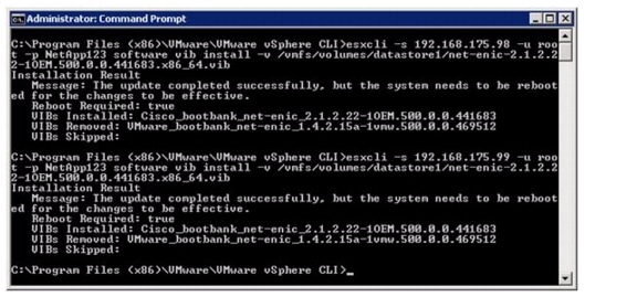
Load Updated Cisco VIC enic Driver Version 2.1.2.22
Download and expand the zip file for the Cisco enic driver, available for the C-Series servers: https://download3.vmware.com/software/SCATEST/Cisco_ENIC/enic_driver_2.1.2.22-564611.zip.
ESXi Hosts VM-Host-Infra-01 and VM-Host-Infra-02
1.
2.
3.
4.
5.
6.
7.
8.
9.
10.
11.
12.
13.
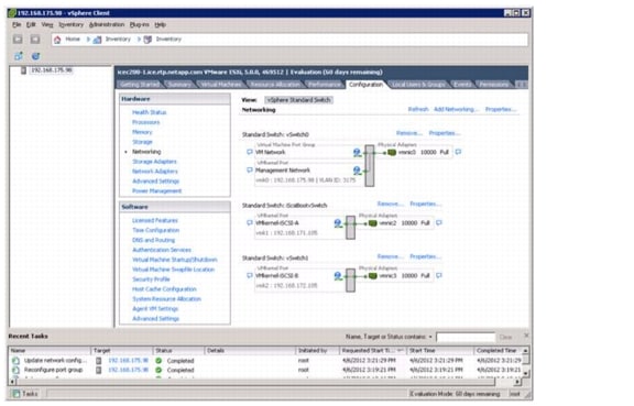
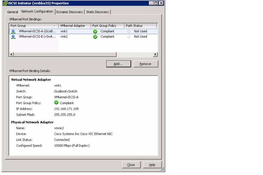
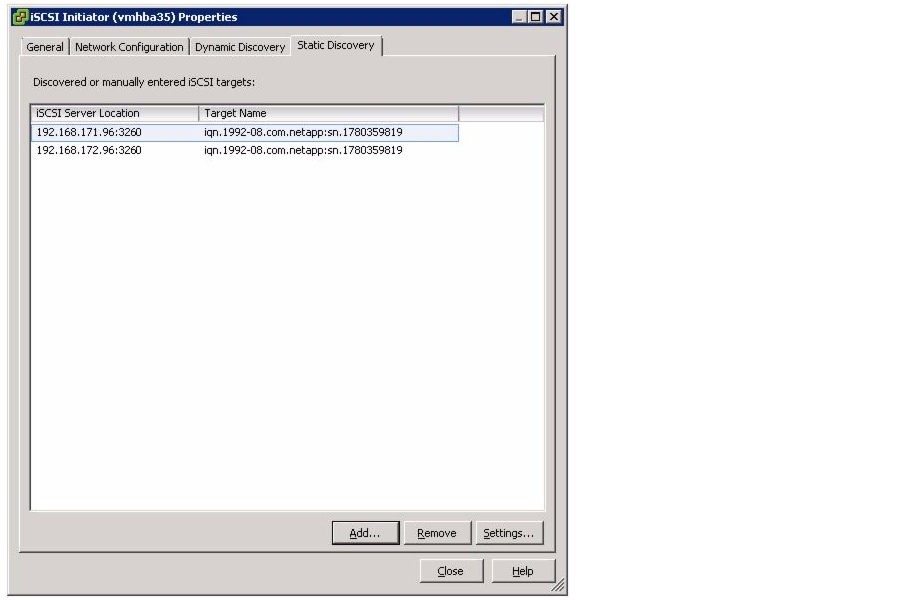
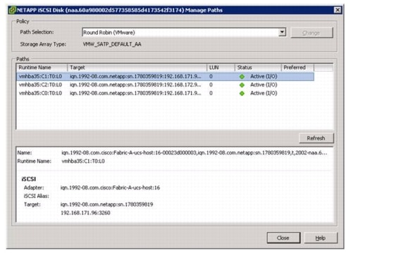
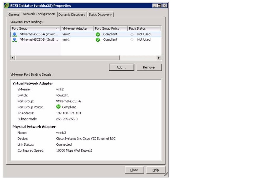
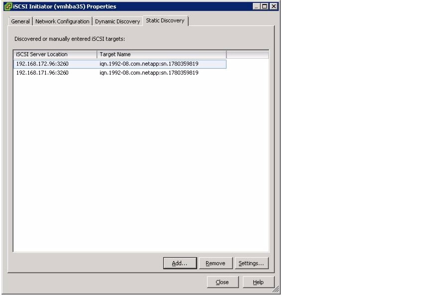
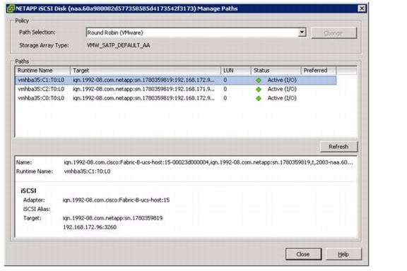
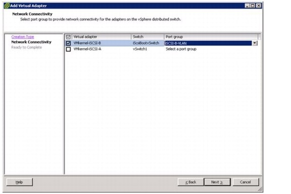
Set Up iSCSI Boot Ports on Virtual Switches
ESXi Host VM-Host-Infra-01
1.
2.
3.
4.
5.
6.
7.
8.
9.
10.
11.
12.
13.
14.
15.
16.
17.
18.
19.
20.
21.
22.
23.
24.
25.
26.
27.
28.
29.
30.
31.
32.
33.
34.
35.
36.
37.
38.
39.
40.
41.
42.
ESXi Host VM-Host-Infra-02
1.
2.
3.
4.
5.
6.
7.
8.
9.
10.
11.
12.
13.
14.
15.
16.
17.
18.
19.
20.
21.
22.
23.
24.
25.
26.
27.
28.
29.
30.
31.
32.
33.
34.
35.
36.
37.
38.
39.
40.
41.
42.
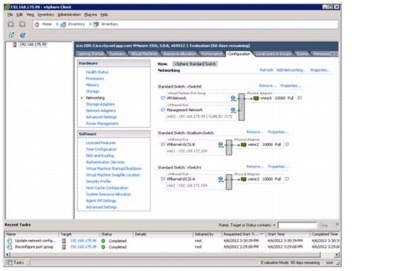
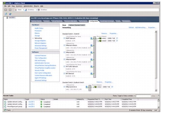
Set Up VMkernel Ports and Virtual Switch
ESXi Host VM-Host-Infra-01
1.
2.
3.
4.
5.
6.
7.
8.
9.
10.
11.
12.
13.
14.
15.
16.
17.
18.
19.
20.
21.
22.
23.
24.
25.
26.
27.
28.
29.
30.
31.
32.
33.
34.
35.
36.
37.
38.
39.
40.
41.
42.
43.
44.
45.
46.
47.
48.
49.
ESXi Host VM-Host-Infra-02
1.
2.
3.
4.
5.
6.
7.
8.
9.
10.
11.
12.
13.
14.
15.
16.
17.
18.
19.
20.
21.
22.
23.
24.
25.
26.
27.
28.
29.
30.
31.
32.
33.
34.
35.
36.
37.
38.
39.
40.
41.
42.
43.
44.
45.
46.
47.
48.
49.
50.
Mount the Required Datastores
ESXi Hosts VM-Host-Infra-01 and VM-Host-Infra-02
1.
2.
3.
4.
5.
6.
7.
8.
9.
10.
11.
12.
13.
14.
15.
16.
17.
18.
19.
NTP Time Configuration
ESXi Hosts VM-Host-Infra-01 and VM-Host-Infra-02
1.
2.
3.
4.
5.
6.
7.
8.
9.
10.
Move the VM Swap File Location
ESXi Hosts VM-Host-Infra-01 and VM-Host-Infra-02
1.
2.
3.
4.
5.
6.
7.
VMware vCenter 5.0 Deployment Procedure
The following sections provide detailed procedures for installing VMware vCenter 5.0 within a VMware vSphere Built On FlexPod With IP-Based Storage environment. The deployment procedures that follow are customized to include the specific environment variables that have been noted in previous sections. By the end of this section, a VMware vCenter server will be configured along with a Microsoft SQL Server providing the database to support vCenter. Although this procedure walks through the installation and configuration of an external Microsoft SQL Server 2008 R2 database, other types of external databases are supported by vCenter. If you choose to use an alternate database, please refer to VMware vSphere 5.0 documentation for how to setup this database and integrate it into vCenter.
Build a Microsoft SQL Server Virtual Machine
1.
2.
3.
4.
5.
6.
7.
8.
9.
10.
11.
12.
13.
14.
15.
16.
17.
18.
19.
20.
21.
22.
23.
24.
25.
26.
27.
28.
29.
30.
31.
32.
33.
34.
35.
36.
37.
38.
39.
40.
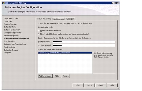
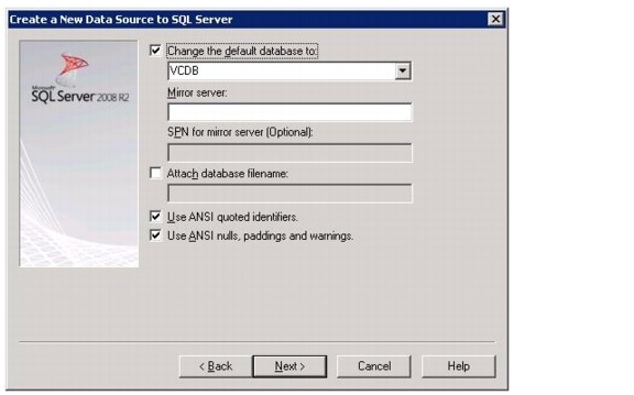
Install Microsoft SQL Server 2008 R2
vCenter SQL Server Virtual Machine
1.
2.
3.
4.
5.
6.
7.
8.
9.
10.
11.
12.
13.
14.
15.
16.
17.
18.
19.
20.
21.
22.
23.
24.
25.
26.
27.
28.
29.
30.
31.
32.
33.
34.
35.
36.
37.
38.
39.
40.
41.
42.
43.
44.
45.
46.
47.
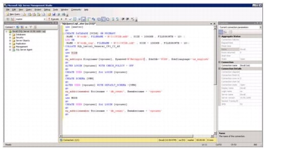
use [master]
go
CREATE DATABASE [VCDB] ON PRIMARY
(NAME = N'vcdb', FILENAME = N'C:\VCDB.mdf' , SIZE = 2000KB , FILEGROWTH = 10% )
LOG ON
(NAME = N'vcdb_log', FILENAME = N'C:\VCDB.ldf' , SIZE = 1000KB , FILEGROWTH = 10%)
COLLATE SQL_Latin1_General_CP1_CI_AS
go
use VCDB
go
sp_addlogin @loginame=[vpxuser], @passwd=N'<Password>', @defdb='VCDB', @deflanguage='us_english'
go
ALTER LOGIN [vpxuser] WITH CHECK_POLICY = OFF
go
CREATE USER [vpxuser] for LOGIN [vpxuser]
go
CREATE SCHEMA [VMW]
go
ALTER USER [vpxuser] WITH DEFAULT_SCHEMA =[VMW]
go
sp_addrolemember @rolename = 'db_owner', @membername = 'vpxuser'
go
use MSDB
go
CREATE USER [vpxuser] for LOGIN [vpxuser]
go
sp_addrolemember @rolename = 'db_owner', @membername = 'vpxuser'
go
48.
49.
50.
Build a VMware vCenter Virtual Machine
Using the instructions above that were used to build the SQL Server VM, build a VMware vCenter Virtual Machine with 4 GB RAM, 2 CPUs, and one virtual network interface in the <MGMT VLAN ID> VLAN. Bring up the virtual machine, install VMware Tools, and assign an IP address and host name in the Active Directory Domain.
1.
2.
3.
4.
5.
6.
7.
8.
9.
10.
11.
12.
13.
14.
15.
16.
17.
18.
19.
20.
21.
22.
Note
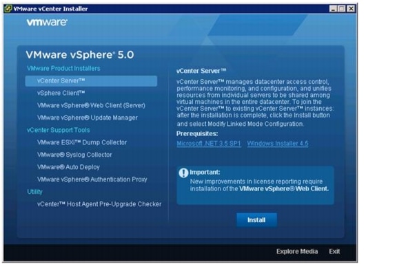
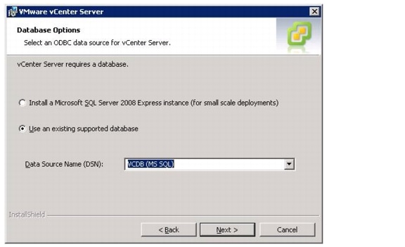
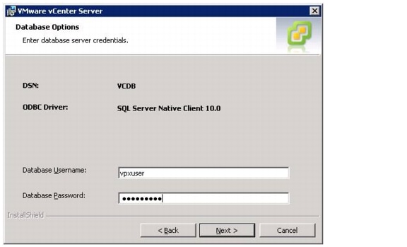
Install VMware vCenter Server
vCenter Server Virtual Machine
1.
2.
3.
4.
5.
6.
7.
8.
9.
10.
11.
12.
13.
14.
15.
16.
17.
18.
19.
20.
21.
22.
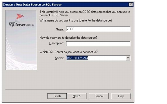
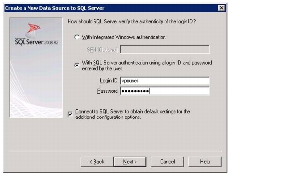
vCenter Setup
1.
2.
3.
4.
5.
6.
7.
8.
9.
10.
11.
12.
13.
14.
15.
16.
17.
18.
19.
20.
21.
22.
NetApp Virtual Storage Console Deployment Procedure
The following subsections through Provisioning and Cloning Setup, provide detailed procedures for installing the NetApp Virtual Storage Console. The deployment procedures that follow are customized to include the environment variables discussed in previous sections. By the end of this section, a VSC will be a configured and operational plug-in with VMware vCenter.
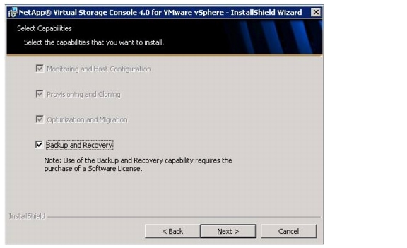
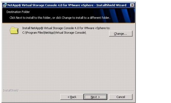
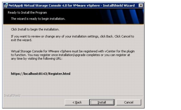
Installing NetApp Virtual Storage Console 4.0
Using the previous instructions for virtual machine creation, build a VSC and OnCommand virtual machine with 4GB RAM, two CPUs, and two virtual network interfaces, one in the <MGMT VLAN ID> VLAN and the other in the <NFS VLAN ID> VLAN. The second virtual network interface should be a VMXNET 3 adapter. Bring up the virtual machine, install VMware Tools, assign IP addresses, and join the machine to the Active Directory domain. Install the current version of Adobe Flash Player on the VM. Install all Windows updates on the virtual machine, but do not install Internet Explorer 9. Keep Internet Explorer 8 on the virtual machine.
1.
2.
3.
4.
5.
6.
7.
8.
9.
10.
11.
12.
13.
14.
15.
16.
Note
17.
18.
19.
20.
21.
22.
23.
24.
25.
26.
27.
28.
29.
30.
31.
a.
b.
c.
d.
e.
f.
Note
Optimal Storage Settings for ESXi Hosts
VSC allows the automated configuration of storage-related settings for all ESXi hosts that are connected to NetApp storage controllers. These steps describe setting the recommended values for NetApp attached ESXi hosts.
1.
2.
Note
Note
Provisioning and Cloning Setup
Provisioning and Cloning in VSC 4.0 helps administrators to provision both VMFS and NFS datastores at the data center, datastore cluster, or host level in VMware environments. Furthermore, the target storage can be storage controllers running in either Cluster-Mode or 7-Mode.
1.
2.
3.
4.
5.
6.
7.
8.
9.
10.
11.
12.
NetApp OnCommand Deployment Procedure
The following subsections provide detailed procedures for installing the NetApp OnCommand software. The deployment procedures that follow are customized to include the environment variables described in previous sections. By the end of this section through Configure Host Services, an OnCommand System Manager will be configured and operational.
Install NetApp OnCommand
1.
2.
3.
4.
5.
6.
7.
Note
8.
9.
10.
Note
11.
12.
13.
14.
15.
Note
16.
17.
Note
Note
18.
–
–
–
–
–
–
Note
19.
–
–
20.
–
Note
–
21.
–
–
–
–
Manually Add Data Fabric Manager Storage Controllers
The following steps provide details for the manual addition of storage controllers into the Data Fabric Manager server.
1.
2.
–
–
3.
–
–
–
–
4.
–
–
–
Note
Run Diagnostics for Verifying Data Fabric Manager Communication
The following steps provide details for verifying Data Fabric Manager communication by running diagnostics. This helps identify misconfigurations that can prevent the Data Fabric Manager server from monitoring or managing a particular appliance, and it should be the first command you use when troubleshooting.
1.
2.
–
–
3.
–
–
Configure Additional Operations Manager Alerts
The following steps provide details for configuring an SNMP trap host as well as configuring daily e-mails from Operations Manager for critical alerts.
1.
2.
3.
Deploy the NetApp OnCommand Host Package
The following steps provide details for deploying the OnCommand Host Package.
1.
2.
3.
4.
5.
6.
7.
8.
9.
10.
11.
12.
13.
14.
15.
16.
17.
18.
19.
20.
21.
Note
22.
23.
24.
25.
Note
Set a Shared Lock Directory to Coordinate Mutually Exclusive Activities on Shared Resources
Note
1.
a.
b.
c.
d.
2.
3.
4.
5.
6.
Install NetApp OnCommand Windows PowerShell Cmdlets
The following steps provide details for installing the NetApp OnCommand Windows PowerShell cmdlets.
1.
2.
3.
Configure Host Services
The following steps provide details for configuring host services.
1.
2.
3.
4.
5.
a.
b.
c.
d.
e.
6.
a.
b.
c.
7.
a.
b.
c.
8.
a.
b.
9.
a.
b.
c.
d.
e.
f.
g.
Appendix
B-Series Deployment Procedure
To add B-Series chassis and servers to an existing Cisco UCS environment with managed C-Series, the first step is to cable ports from the FEX modules on the back of the chassis to the Cisco UCS 6248 fabric interconnects. On the back of the chassis, the FEX on the left cables to the Fabric A fabric interconnect. The FEX on the right cables to the Fabric B fabric interconnect. Depending on the FEX type, one, two, four, or eight uplink cables can be run from each FEX to the corresponding fabric interconnect.
In this particular implementation of FlexPod, the Global Chassis Discover Policy in the Equipment tab of the Cisco UCS Manager was set to "2 Link," requiring a minimum of two uplinks to be run from each FEX to the fabric interconnect. It is important to use the same number of uplinks on each fabric. If the chassis you are connecting has Cisco UCS 2104XP FEXs, you must change the Link Grouping Preference of the Global Chassis Discovery Policy to None. You must also change the Connectivity Policy of each rack-mount FEX to an Admin State of Port Channel.
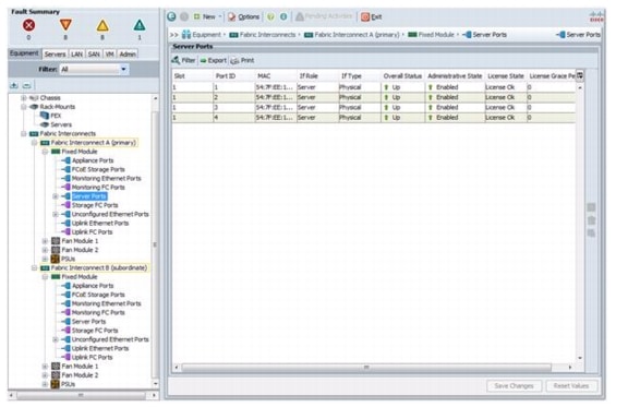
When the chassis has been cabled to the fabric interconnects, go into the UCS Manager and designate the uplink ports from the chassis as Server ports. At this point, the chassis and blades should be automatically discovered and listed in the Equipment tab of the Cisco UCS Manager. The blades can then be added to server pools and assigned to service profiles.
Note
In the validation for this Cisco Validated Design, a Cisco UCS blade chassis was added to the FlexPod environment, service profiles were assigned to blades, the blades were iSCSI booted, and VMware ESXi 5.0 was installed on the blades to validate that B-Series can be mixed with a Cisco UCS C-Series in this FlexPod environment (Figure 4).
Figure 4 VMware vSphere Built On FlexPod With IP-Based Storage Environment
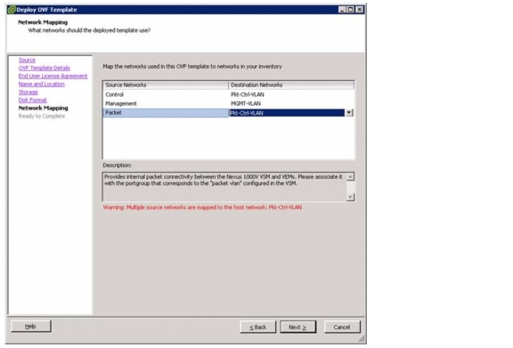
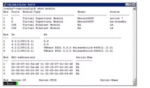
Cisco Nexus 1000v Deployment Procedure
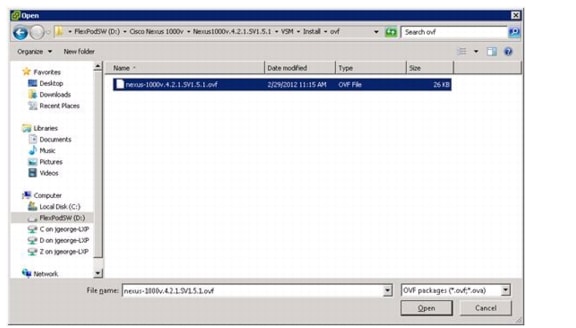
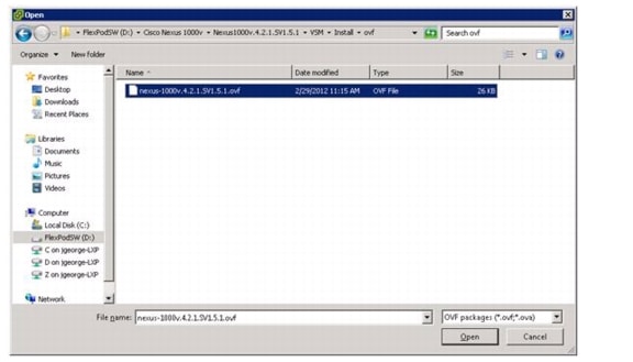
The following sections provide detailed procedures for installing a high-availability Cisco Nexus 1000v in FlexPod configuration with IP-based storage. Since this configuration is intended to minimize costs, the primary and standby Cisco Nexus 1000v Virtual Supervisor Modules (vsm) will be installed in virtual machines in the environment. The deployment procedures that follow are customized to include the specific environment variables that have been noted in previous sections. By the end of this section, a Nexus 1000v distributed virtual switch (dvs) will be provisioned. This procedure assumes that the Cisco Nexus 1000v software version 4.2.1.SV1.5.1 has been downloaded from www.cisco.com and expanded. This procedure also assumes that VMware vSphere 5.0 Enterprise Plus licensing is installed.
Log into Both Cisco Nexus 5548 Switches
1.
Add Packet-Control VLAN to Switch Trunk Ports
Nexus A and Nexus B
1.
2.
3.
4.
5.
6.
7.
8.
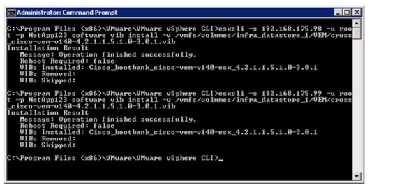
9.
10.
11.
12.
13.
14.
15.
Log Into Cisco UCS Manager
Cisco UCS Manager
These steps provide details for logging into the Cisco UCS environment.
1.
2.
3.
4.
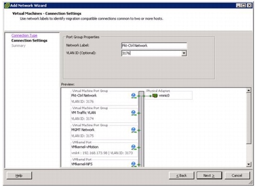
Add Packet-Control VLAN to Host Server vNICs
Cisco UCS Manager
1.
2.
3.
4.
5.
6.
7.
8.
9.
10.
11.
12.
13.
Log in to the VMware vCenter
1.
Install the Virtual Ethernet Module (VEM) on Each ESXi Host
1.
2.
3.
4.
5.
6.
7.
8.
9.
10.
11.
Adjust ESXi Host Networking
1.
2.
3.
4.
5.
6.
7.
8.
9.
10.
Deploy the Primary VSM
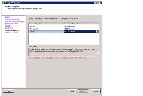
1.
2.
3.
4.
5.
6.
7.
8.
9.
10.
11.
12.
13.
Base Configuration of the Primary VSM
1.
2.
3.
4.
5.
6.
7.
8.
9.
10.
11.
12.
13.
14.
15.
16.
17.
18.
19.
20.
21.
22.
23.
24.
25.
26.
27.
28.
29.
30.
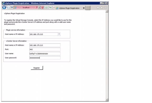
Register the Nexus 1000v as a vCenter Plugin
1.
2.
3.
4.
5.
6.
7.
8.
9.
10.
11.
12.
Base Configuration of the Primary VSM
1.
2.
3.
4.
5.
6.
7.
8.
9.
10.
11.
12.
13.
14.
15.
16.
17.
18.
19.
20.
21.
22.
23.
24.
25.
26.
27.
28.
29.
30.
31.
32.
33.
34.
35.
36.
37.
38.
39.
40.
41.
42.
43.
44.
45.
46.
47.
48.
49.
50.
51.
52.
53.
54.
55.
56.
57.
58.
59.
60.
61.
62.
63.
64.
65.
66.
67.
68.
69.
70.
71.
72.
73.
74.
75.
76.
77.
78.
79.
80.
81.
82.
83.
84.
85.
86.
87.
88.
89.
90.
91.
92.
93.
94.
95.
96.
97.
98.
99.
100.
101.
102.
103.
104.
105.
106.
107.
108.
109.
110.
111.
112.
113.
114.
115.
Migrate the ESXi Hosts' Networking to the Nexus 1000v
1.
2.
3.
4.
5.
6.
7.
8.
9.
10.
11.
12.
13.
14.
15.
16.
17.
18.
19.
20.
21.
22.
23.
24.
25.
26.
27.
28.
29.
30.
31.
32.
33.
34.
35.
36.
37.
38.
39.
40.
41.
42.
43.
44.
45.
46.
47.
48.
49.
50.
51.
52.
53.
54.
55.
56.
57.
58.
59.
60.
61.
62.
63.
64.
65.
66.
67.
68.
69.
70.
71.
72.
73.
74.
75.
76.
77.
78.
79.
80.
81.
82.
83.
Deploy the Secondary VSM
1.
2.
3.
4.
5.
6.
7.
8.
9.
10.
11.
12.
13.
Base Configuration of the Secondary VSM
1.
2.
3.
4.
5.
6.
Nexus 5548 Reference Configurations
Nexus A
!Command: show running-config
!Time: Wed Apr 11 22:18:20 2012
version 5.1(3)N2(1)
no feature telnet
no telnet server enable
cfs eth distribute
feature lacp
feature vpc
feature lldp
username admin password 5 $1$VbxAbFP3$7nWUsAzHL8Ps9X1lCMqxG/ role network-admin
ip domain-lookup
switchname ice5548-1
class-map type qos class-fcoe
class-map type queuing class-fcoe
match qos-group 1
class-map type queuing class-all-flood
match qos-group 2
class-map type queuing class-ip-multicast
match qos-group 2
class-map type network-qos class-fcoe
match qos-group 1
class-map type network-qos class-all-flood
match qos-group 2
class-map type network-qos class-ip-multicast
match qos-group 2
policy-map type network-qos jumbo
class type network-qos class-default
mtu 9000
multicast-optimize
system qos
service-policy type network-qos jumbo
snmp-server user admin network-admin auth md5 0x2e8af112d36e9af1466f4e4db0ce36a3
priv 0x2e8af112d36e9af1466f4e4db0ce36a3 localizedkey
snmp-server enable traps entity fru
ntp server 192.168.175.4 use-vrf management
vrf context management
ip route 0.0.0.0/0 192.168.175.1
vlan 1
vlan 2
name Native-VLAN
vlan 3170
name NFS-VLAN
vlan 3171
name iSCSI-A-VLAN
vlan 3172
name iSCSI-B-VLAN
vlan 3173
name vMotion-VLAN
vlan 3174
name VM-Traffic-VLAN
vlan 3175
name MGMT-VLAN
spanning-tree port type edge bpduguard default
spanning-tree port type edge bpdufilter default
spanning-tree port type network default
vpc domain 7
role priority 10
peer-keepalive destination 192.168.175.70 source 192.168.175.69
interface port-channel10
description vPC peer-link
switchport mode trunk
vpc peer-link
switchport trunk native vlan 2
switchport trunk allowed vlan 3170-3175
spanning-tree port type network
interface port-channel11
description ice2240-1a
switchport mode trunk
vpc 11
switchport trunk native vlan 2
switchport trunk allowed vlan 3170-3172
spanning-tree port type edge trunk
interface port-channel12
description ice2240-1b
switchport mode trunk
vpc 12
switchport trunk native vlan 2
switchport trunk allowed vlan 3170-3172
spanning-tree port type edge trunk
interface port-channel13
description iceucsm-7a
switchport mode trunk
vpc 13
switchport trunk native vlan 2
switchport trunk allowed vlan 3170-3171,3173-3175
spanning-tree port type edge trunk
interface port-channel14
description iceucsm-7b
switchport mode trunk
vpc 14
switchport trunk native vlan 2
switchport trunk allowed vlan 3170,3172-3175
spanning-tree port type edge trunk
interface port-channel20
description icecore uplink
switchport mode trunk
vpc 20
switchport trunk native vlan 2
switchport trunk allowed vlan 3175
spanning-tree port type network
interface Ethernet1/1
description ice2240-1a:e1a
switchport mode trunk
switchport trunk native vlan 2
switchport trunk allowed vlan 3170-3172
channel-group 11 mode active
interface Ethernet1/2
description ice2240-1b:e1a
switchport mode trunk
switchport trunk native vlan 2
switchport trunk allowed vlan 3170-3172
channel-group 12 mode active
interface Ethernet1/3
description iceucsm-7a:Eth1/19
switchport mode trunk
switchport trunk native vlan 2
switchport trunk allowed vlan 3170-3171,3173-3175
channel-group 13 mode active
interface Ethernet1/4
description iceucsm-7b:Eth1/19
switchport mode trunk
switchport trunk native vlan 2
switchport trunk allowed vlan 3170,3172-3175
channel-group 14 mode active
interface Ethernet1/5
description ice5548-2:Eth1/5
switchport mode trunk
switchport trunk native vlan 2
switchport trunk allowed vlan 3170-3175
channel-group 10 mode active
interface Ethernet1/6
description ice5548-2:Eth1/6
switchport mode trunk
switchport trunk native vlan 2
switchport trunk allowed vlan 3170-3175
channel-group 10 mode active
interface Ethernet1/7
interface Ethernet1/8
interface Ethernet1/9
interface Ethernet1/10
interface Ethernet1/11
interface Ethernet1/12
interface Ethernet1/13
interface Ethernet1/14
interface Ethernet1/15
interface Ethernet1/16
interface Ethernet1/17
interface Ethernet1/18
interface Ethernet1/19
interface Ethernet1/20
description icecore:Eth1/21
switchport mode trunk
switchport trunk native vlan 2
switchport trunk allowed vlan 3175
channel-group 20 mode active
interface Ethernet1/21
interface Ethernet1/22
interface Ethernet1/23
interface Ethernet1/24
interface Ethernet1/25
interface Ethernet1/26
interface Ethernet1/27
interface Ethernet1/28
interface Ethernet1/29
interface Ethernet1/30
interface Ethernet1/31
interface Ethernet1/32
interface mgmt0
ip address 192.168.175.69/24
line console
line vty
boot kickstart bootflash:/n5000-uk9-kickstart.5.0.3.N2.2b.bin
boot system bootflash:/n5000-uk9.5.0.3.N2.2b.binNexus B
!Command: show running-config
!Time: Wed Apr 11 22:26:15 2012
version 5.1(3)N2(1)
no feature telnet
no telnet server enable
cfs eth distribute
feature lacp
feature vpc
feature lldp
username admin password 5 $1$4ght.2ge$Yj1LG2JEPqWnJVwz544lQ0 role network-admin
ip domain-lookup
switchname ice5548-2
class-map type qos class-fcoe
class-map type queuing class-fcoe
match qos-group 1
class-map type queuing class-all-flood
match qos-group 2
class-map type queuing class-ip-multicast
match qos-group 2
class-map type network-qos class-fcoe
match qos-group 1
class-map type network-qos class-all-flood
match qos-group 2
class-map type network-qos class-ip-multicast
match qos-group 2
policy-map type network-qos jumbo
class type network-qos class-default
mtu 9000
multicast-optimize
system qos
service-policy type network-qos jumbo
snmp-server user admin network-admin auth md5 0xe481d1d2fee4aaa498237df1852270e8
priv 0xe481d1d2fee4aaa498237df1852270e8 localizedkey
snmp-server enable traps entity fru
ntp server 192.168.175.4 use-vrf management
vrf context management
ip route 0.0.0.0/0 192.168.175.1
vlan 1
vlan 2
name Native-VLAN
vlan 3170
name NFS-VLAN
vlan 3171
name iSCSI-A-VLAN
vlan 3172
name iSCSI-B-VLAN
vlan 3173
name vMotion-VLAN
vlan 3174
name VM-Traffic-VLAN
vlan 3175
name MGMT-VLAN
spanning-tree port type edge bpduguard default
spanning-tree port type edge bpdufilter default
spanning-tree port type network default
vpc domain 7
role priority 20
peer-keepalive destination 192.168.175.69 source 192.168.175.70
interface port-channel10
description vPC peer-link
switchport mode trunk
vpc peer-link
switchport trunk native vlan 2
switchport trunk allowed vlan 3170-3175
spanning-tree port type network
interface port-channel11
description ice2240-1a
switchport mode trunk
vpc 11
switchport trunk native vlan 2
switchport trunk allowed vlan 3170-3172
spanning-tree port type edge trunk
interface port-channel12
description ice2240-1b
switchport mode trunk
vpc 12
switchport trunk native vlan 2
switchport trunk allowed vlan 3170-3172
spanning-tree port type edge trunk
interface port-channel13
description iceucsm-7a
switchport mode trunk
vpc 13
switchport trunk native vlan 2
switchport trunk allowed vlan 3170-3171,3173-3175
spanning-tree port type edge trunk
interface port-channel14
description iceucsm-7b
switchport mode trunk
vpc 14
switchport trunk native vlan 2
switchport trunk allowed vlan 3170,3172-3175
spanning-tree port type edge trunk
interface port-channel20
description icecore uplink
switchport mode trunk
vpc 20
switchport trunk native vlan 2
switchport trunk allowed vlan 3175
spanning-tree port type network
interface Ethernet1/1
description ice2240-1a:e1b
switchport mode trunk
switchport trunk native vlan 2
switchport trunk allowed vlan 3170-3172
channel-group 11 mode active
interface Ethernet1/2
description ice2240-1b:e1b
switchport mode trunk
switchport trunk native vlan 2
switchport trunk allowed vlan 3170-3172
channel-group 12 mode active
interface Ethernet1/3
description iceucsm-7a:Eth1/20
switchport mode trunk
switchport trunk native vlan 2
switchport trunk allowed vlan 3170-3171,3173-3175
channel-group 13 mode active
interface Ethernet1/4
description iceucsm-7b:Eth1/20
switchport mode trunk
switchport trunk native vlan 2
switchport trunk allowed vlan 3170,3172-3175
channel-group 14 mode active
interface Ethernet1/5
description ice5548-1:Eth1/5
switchport mode trunk
switchport trunk native vlan 2
switchport trunk allowed vlan 3170-3175
channel-group 10 mode active
interface Ethernet1/6
description ice5548-1:Eth1:6
switchport mode trunk
switchport trunk native vlan 2
switchport trunk allowed vlan 3170-3175
channel-group 10 mode active
interface Ethernet1/7
interface Ethernet1/8
interface Ethernet1/9
interface Ethernet1/10
interface Ethernet1/11
interface Ethernet1/12
interface Ethernet1/13
interface Ethernet1/14
interface Ethernet1/15
interface Ethernet1/16
interface Ethernet1/17
interface Ethernet1/18
interface Ethernet1/19
interface Ethernet1/20
description icecore:Eth1/22
switchport mode trunk
switchport trunk native vlan 2
switchport trunk allowed vlan 3175
channel-group 20 mode active
interface Ethernet1/21
interface Ethernet1/22
interface Ethernet1/23
interface Ethernet1/24
interface Ethernet1/25
interface Ethernet1/26
interface Ethernet1/27
interface Ethernet1/28
interface Ethernet1/29
interface Ethernet1/30
interface Ethernet1/31
interface Ethernet1/32
interface mgmt0
ip address 192.168.175.70/24
line console
line vty
boot kickstart bootflash:/n5000-uk9-kickstart.5.0.3.N2.2b.bin
boot system bootflash:/n5000-uk9.5.0.3.N2.2b.bin