Feedback Feedback
|
Table Of Contents
Assembling a Pedestal Stand-Mounted Cisco TelePresence System 500-32
Assembling a Pedestal Stand-Mounted Cisco TelePresence System 500-32
May 29, 2013, OL-23420-01This chapter describes the tasks you perform to assemble your Cisco TelePresence System 500-32 (CTS-500-32) and includes the following sections:
•
CTS-500-32 Installation Video
Note
Required Tools and Resources
A #1 screwdriver is required to secure the base to the display assembly.
Two people are required to install this system.
CTS-500-32 Installation Video
A video that shows the entire hardware installation process is available at the following URL:
Assembling the CTS-500-32
Perform the following steps to assemble the CTS-500-32 for use.
Step 1
•
–
–
Note
Step 2
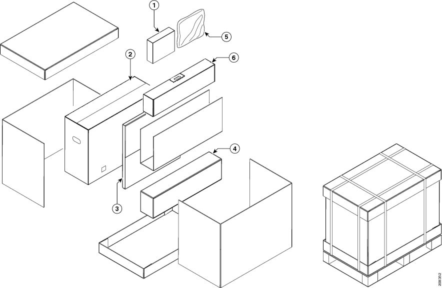
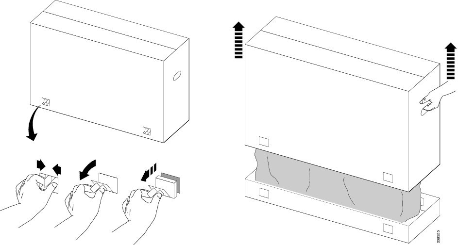
Figure 2-1 shows the carton contents. The contents are labeled with orange stickers and the callouts in Figure 2-1 correspond to the numbers on the labels.
Figure 2-1 Carton Contents
Step 3
WarningFigure 2-2 Removing the Base from the Carton and Plywood Packing
Step 4
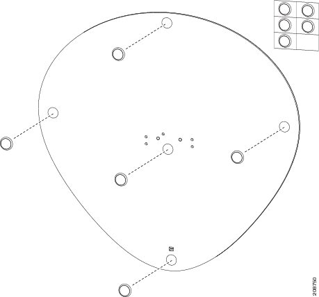
The base packaging contains two sets of foot pads; attach either the black set or the white set to the underside of the base. Use the following criteria to choose the correct set:
•
•
Figure 2-3 Attaching the Foot Pads to the Base
Step 5
a.
b.
c.
d.
e.
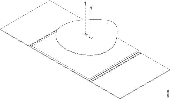
Tip
Figure 2-4 Attaching the Column to the Base
Step 6
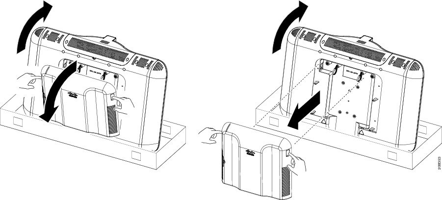
Figure 2-5 Unpacking the Display
Step 7
Figure 2-6 Removing the Rear Display Cover
Step 8
Note
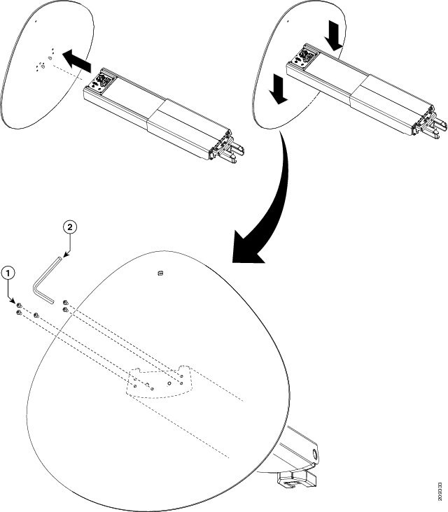
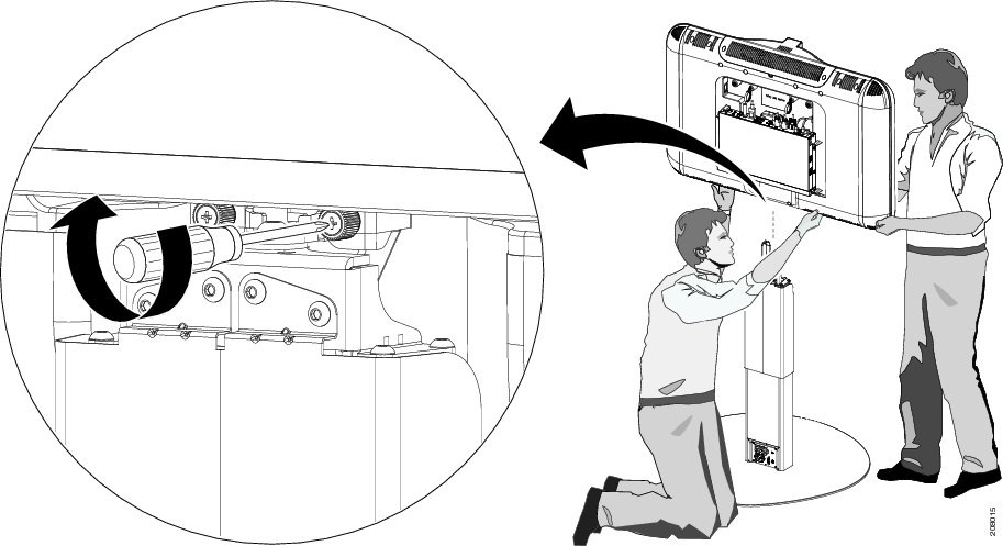
Tip
Figure 2-7 Placing and Securing the Display on the Column
Step 9
Tip
Tip
http://www.cisco.com/en/US/docs/telepresence/cts_500/cts_500_32/assembly/guide/video/
cts50032_installation_640x360.html
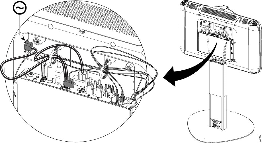
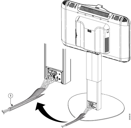
The cable routing part of the video starts at 4 minutes and runs until the end of the video.Figure 2-8 Routing the Cables from the Column
Step 10
Tip
Tip
Note
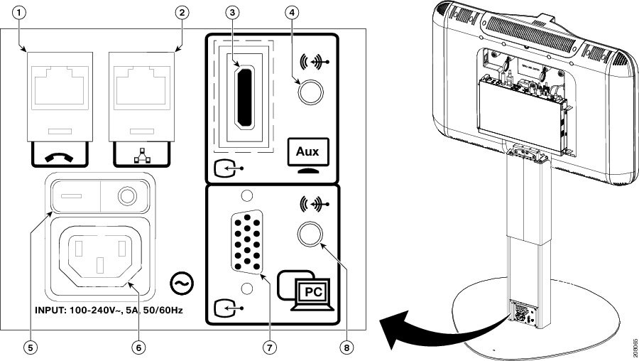
Figure 2-9 Connecting the Cables to the Display
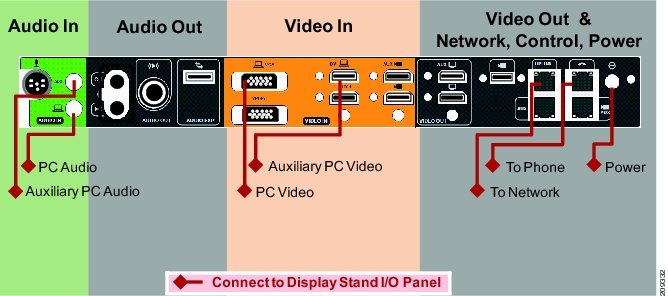
Figure 2-10 Required Codec Cable Connections Between the Pedestal and the Display
Figure 2-11 Connection Diagram for CTS-500-32 Codec Showing All Connections (for Reference Only)
Step 11
The following numbers correspond to the called out numbers in the diagram.
1.
2.
3.
4.
5.
6.
7.
8.
1 Use this port to share presentations when you are not in a call. To share presentations during a call, use the VGA port and the VGA-to-VGA cable (callout 7).
2 Use only the HD Video cable that is provided by Cisco; HDMI cables do not work with the CTS-500-32.
3 You can use your CTS-500-32 as a primary or secondary data display for your PC when you are not in a conference; use this HD Video connection for that purpose.
4 To use this as a DMP input, swap the input connection on the codec labeled as "Auxiliary PC Video" in Figure 2-10 with the connection labeled "Auxiliary Input (ex.DMP") in Figure 2-11 and connect the HDMI connection on the stand base labeled "Aux" to the DMP. For more information about using a DMP with your CTS 500-32 system, see the "Options for the Cisco TelePresence System 500 32" section of the Cisco TelePresence Hardware Options and Upgrade Guide.
Figure 2-12 Lower Column Power and Signal Cables
Step 12
Step 13
Figure 2-13 Installing the Cable Sheath
Step 14
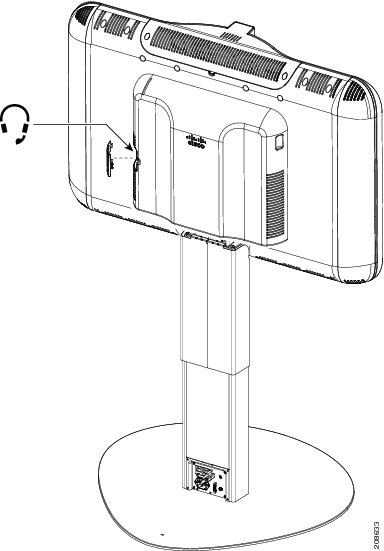
Figure 2-14 Attaching a Headset to the CTS-500-32 (Optional)
Step 15
Step 16
Step 17