Table Of Contents
Release Notes for Cisco MGX 8850 Software Version 2.1.70
Contents
About Release 2.1.70
Type of Release
Locating Software Updates
Acronyms
System Requirements
Software/Firmware Compatibility Matrix
Additional Compatibility Information
Hardware Supported
Hardware Compatibility Matrix
New and Changed Information
New Features
OAM Loopback
ITU-T APS Annex B
XPVC/XPVP Termination on AXSM-E
Config Verify
Enhancements in Release 2.1.70
Additional Software Information
MIB
Service Class Template File Information
New Hardware Supported in Release 2.1.70
Hardware Overview
New and Changed Commands
New and Changed Commands
New Commands
Changed Commands
Removed Commands
Limitations and Restrictions
General Limitations, Restrictions, and Notes
Important Notes
AXSM-E Limitations
RPM-PR and MPLS Limitations, Restrictions, and Notes
RPM-PR and MPLS Notes
Booting the RPM-PR
RPM-PR Bootflash Precautions
APS Management Information
Preparing for Intercard APS
Managing Intercard APS Lines
Troubleshooting APS Lines
Clearing the Configuration on Redundant PXM45 Cards
Recommendations
Installing and Upgrading to Release 2.1.70
Upgrade Process Overview
Quickstart Procedures for Software Upgrades
Browsing the File System
Copying Software Files to the Switch
Upgrade Procedures for PXM45 and AXSM Cards
Upgrade Procedures for RPM-PR Cards
Troubleshooting Upgrade Problems
Documentation
Related Documentation
Cisco WAN Manager Release 10.5 Documentation
Cisco MGX 8850 Release 2.1 Documentation
SES PNNI Release 1.1 Documentation
Cisco WAN Switching Software, Release 9.3 Documentation
MGX 8850 Multiservice Switch, Release 1.1.40 Documentation
MGX 8250 Edge Concentrator, Release 1.1.40 Documentation
MGX 8230 Multiservice Gateway, Release 1.1.40 Documentation
Ordering Documentation
Documentation on the World Wide Web
Documentation CD-ROM
Documentation Feedback
Technical Assistance
Cisco.com
Technical Assistance Center
Contacting TAC by Using the Cisco TAC Website
Contacting TAC by Telephone
Caveats
Known Anomalies for Release 2.1.70
Anomalies Resolved in Release 2.1.70
Anomaly Status Changes in Release 2.1.70
Known Anomalies in Release 2.1.60
Anomalies Resolved in Release 2.1.60
Anomaly Status Changes in Release 2.1.60
Known Anomalies in Release 2.1.10
Anomalies Resolved in Release 2.1.10
Anomaly Status Changes in Release 2.1.10
Anomalies Resolved in Release 2.1.00
Known RPM-PR/MPLS Anomalies
Known Anomalies for RPM
Anomalies Resolved for RPM /MPLS
Release Notes for Cisco MGX 8850 Software Version 2.1.70
Contents
About Release 2.1.70
These release notes describe the new features, system requirements, and limitations that apply to Release 2.1.70 for the MGX 8850 IP + ATM backbone switch. These notes also contain Cisco support information.
This document is to be used in conjunction with the documents listed in the "Related Documentation" section.
Type of Release
Release 2.1.70 is a software release for MGX 8850 switches that use the PXM45 processor card.
Locating Software Updates
Software updates are located at Cisco Connection Online (CCO) at http://www.cisco.com/kobayashi/sw-center/wan-planner.shtml.
Acronyms
Table 1 lists acronyms used in these release notes.
Table 1 Acronyms Used in These Release Notes
Acronym
|
Description
|
ABRFS
|
ABRFS: Available Bit Rate - Foresight
|
ABRSTD
|
ABRFS: Available Bit Rate - Standard
|
AINI
|
ATM Inter-Network Interface
|
APS
|
automatic protection switching
|
AR
|
Auto Route
|
ATM
|
asynchronous transfer mode
|
AXSM
|
ATM Switch Service Module
|
B-ISUP
|
Broadband ISDN User Part
|
BPX
|
broadband packet exchange
|
BXM
|
broadband switch module
|
BXM-E
|
broadband switch module - enhanced
|
CC
|
continuity check
|
CLI
|
command line interface
|
CM
|
connection manager
|
CPE
|
customer premises equipment
|
CRC
|
cyclic redundancy check
|
CWM
|
Cisco Wide Area Network Manager
|
DSLAM
|
digital subscriber line access module
|
ENNI
|
enhanced network-to-network Interface
|
FCES
|
Flow Control External Segment
|
FRSM
|
frame relay service module
|
IETF
|
Internet Engineering Task Force
|
ILMI
|
Interim Local Management Interface
|
IOS
|
internet operating system
|
ITU-T
|
International Telecommunication Union-Telecommunication
|
LDP
|
label distribution protocol
|
LMI
|
local management interface
|
LOS
|
loss of signal
|
LSC
|
label switch controller
|
LSP
|
label switched paths
|
LSR
|
label switch router
|
MGX
|
Multiservice Gigabit Switch
|
MIB
|
management information base
|
MPG
|
multiple peer group
|
MPLS
|
multiple protocol label switching
|
NCDP
|
network clock distribution protocol
|
NNI
|
network-to-network interface
|
OAM
|
Operations, Administration, and Maintenance
|
PNNI
|
private network-to-network interface
|
PVC
|
permanent virtual circuit
|
PXM
|
processor switch module
|
RDI
|
remote defect indicator
|
RPM
|
route processor module
|
RPM-PR
|
route processor module - Premium
|
SCT
|
service class template
|
SLA
|
service level agreement
|
SM
|
service module (a card)
|
SMFIR
|
single mode fiber - intermediate range
|
SNMP
|
simple network management protocol
|
SPVC
|
soft permanent virtual connection
|
SVC
|
switched virtual circuit
|
UNI
|
User-Network Interface
|
VCI
|
virtual channel identifier
|
VNNI
|
virtual network-to-network interface
|
VPI
|
virtual path identifier
|
VsVd
|
Virtual Source, Virtual Destination
|
WFQ
|
Weighted Fair Queuing (algorithm)
|
XLMI
|
extended local management interface
|
XPVC
|
extended permanent virtual circuit
|
System Requirements
This section describes software compatible with this release, and lists the hardware supported in this release.
Software/Firmware Compatibility Matrix
Table 2 lists Cisco WAN or IOS products that are interoperable with MGX Release 2.1.70.
Table 2 MGX and RPM Software Version Compatibility Matrix
Cisco WAN or IOS Products
|
Current Release
|
One release before current release
|
Two releases before current release
|
CWM
|
10.5.10
|
n/a
|
n/a
|
MGX 1
|
1.2.00
|
1.1.40
|
1.1.34
|
MGX 2
|
2.1.70
|
2.1.60
|
2.0.15
|
BPG/IGX
|
9.3.35
|
9.3.24
|
9.2.40
|
MGX 8220
|
5.0.17
|
4.1.11
|
n/a
|
SES
|
1.1.70
|
n/a
|
1.0.15
|
Firmware
|
latest for all
|
n/a
|
n/a
|
IOS
|
12.2(4)T1
|
12.2(4)T
|
12.2(2)T3
|
VISM
|
2.2
|
2.1.1 (1 pair)
|
1.5.6 (1 pair)
|
Table 3 lists the software that is compatible for use in a switch running Release 2.1.70 software. Note that the AXSM/B cards use the same software as AXSM cards.
Table 3 MGX and RPM Software Version Compatibility Matrix
Board Pair
|
Boot Software
|
Minimum
Boot Code
Version
|
Runtime Software
|
Latest
Firmware
Version
|
Minimum
Firmware
Version
|
PXM45
|
pxm45_002.001.070.202_bt.fw
|
2.1.70
|
pxm45_002.001.070.202_mgx.fw
|
2.1.70
|
2.1.70
|
PXM45/B
|
pxm45_002.001.070.202_bt.fw
|
2.1.70
|
pxm45_002.001.070.202_mgx.fw
|
2.1.70
|
2.1.70
|
AXSM-1-2488
|
axsm_002.001.070.202_bt.fw
|
2.1.70
|
axsm_002.001.070.202.fw
|
2.1.70
|
2.1.70
|
AXSM-16-155
|
AXSM-4-622
|
AXSM-16-T3/E3
|
AXSM-1-2488/B
|
axsm_002.001.070.202_bt.fw
|
2.1.70
|
axsm_002.001.070.202.fw
|
2.1.70
|
2.1.70
|
AXSM-16-155/B
|
AXSM-4-622/B
|
AXSM-16-T3/E3/B
|
AXSM-2-622-E
|
axsme_002.001.070.202_bt.fw
|
2.1.70
|
axsme_002.001.070.202.fw
|
2.1.70
|
2.1.70
|
AXSM-8-155-E
|
AXSM-16-T3E3-E
|
RPM-PR
|
rpm-boot-mz.122-4.T1
|
12.2(4)T1
|
rpm-js-mz.122-4.T1
|
12.2(4)T1
|
12.2(4)T1
|
Additional Compatibility Information
The following notes provide additional compatibility information for this release:
• You can gracefully upgrade to Release 2.1.70 from Releases 2.0.15, 2.1.10, and 2.1.60.
•MGX 2.1.70 interoperates with SES PNNI 1.1.70 plus BPX Switch Software (SWSW) 9.3.35 plus BXM MFR.
•This release supports feeder connections from Cisco MGX 8850 Release 1.1.40. Please see the "Release Notes for MGX 8850, 8230, and 8250 Software Version 1.1.40" for feeder feature issues. Release notes can be downloaded from http://www.cisco.com/univercd/cc/td/doc/product/wanbu/index.htm.
•You must use CWM Release 10.5.10 to manage networks that contain MGX 8850 switches running Release 2.1.70.
•The RPM-PR software in this release is based on IOS Release 12.2(4)T1.
Hardware Supported
Table 4 lists the hardware supported in Release 2.1.70.
Table 4 Hardware Supported in Release 2.1.70 for MGX 8850
Product ID
|
800 Part Number
|
Minimum Revision
|
AXSM-1-2488
|
800-05795-05
|
-A0
|
AXSM-1-2488/B
|
800-07983-02
|
-A0
|
AXSM-16-155
|
800-05776-06
|
-A0
|
AXSM-16-155/B
|
800-07909-05
|
-A0
|
AXSM-16-T3/E3
|
800-05778-08
|
-A0
|
AXSM-16-T3/E3/B
|
800-07911-05
|
-A0
|
AXSM-16-T3E3-E
|
800-18519-02
|
-A0
|
AXSM-2-622-E
|
800-18521-02
|
-A0
|
AXSM-4-622
|
800-05774-09
|
-B0
|
AXSM-4-622/B
|
800-07910-05
|
-A0
|
AXSM-8-155-E
|
800-18520-02
|
-A0
|
MGX-APS-CON-8850
|
800-05307-01
|
-A0
|
MGX-MMF-FE
|
800-03202-02
|
-A0
|
MGX-RJ45-4E/B
|
800-12134-01
|
-A0
|
MGX-RJ45-FE
|
800-02735-02
|
-A0
|
MMF-4-155/C
|
800-07408-02
|
-A0
|
MMF-8-155-MT
|
800-04819-01
|
-A1
|
MMF-8-155-MT/B
|
800-07120-02
|
-A0
|
PXM45
|
800-06147-07
|
-B0
|
PXM45/B
|
800-09266-04
|
-A0
|
PXM-HD
|
800-05052-03
|
-A0
|
PXM-UI-S3
|
800-05787-02
|
-A0
|
RPM-PR-256
|
800-07178-02
|
-A0
|
RPM-PR-512
|
800-07656-02
|
-A0
|
SMB-4-155
|
800-07425-02
|
-A0
|
SMB-8-E3
|
800-04093-02
|
-A0
|
SMB-8-T3
|
800-05029-02
|
-A0
|
SMFIR-1-622/C
|
800-07410-02
|
-A0
|
SMFIR-2-622
|
800-05383-01
|
-A1
|
SMFIR-2-622/B
|
800-07412-02
|
-B0
|
SMFIR-4-155/C
|
800-07108-02
|
-A0
|
SMFIR-8-155-LC
|
800-05342-01
|
-B0
|
SMFIR-8-155-LC/B
|
800-07864-02
|
-B0
|
SMFLR-1-2488
|
800-06635-04
|
-A0
|
SMFLR-1-2488/B
|
800-08847-01
|
-A0
|
SMFLR-1-622/C
|
800-07411-02
|
-A0
|
SMFLR-2-622
|
800-05385-01
|
-A1
|
SMFLR-2-622/B
|
800-07413-02
|
-B0
|
SMFLR-4-155/C
|
800-07409-02
|
-A0
|
SMFSR-1-2488
|
800-05490-05
|
-A0
|
SMFSR-1-2488/B
|
800-07255-01
|
-A0
|
SMFXLR-1-2488
|
800-05793-05
|
-A0
|
SMFXLR-1-2488/B
|
800-08849-01
|
-A0
|
Hardware Compatibility Matrix
Table 5 shows which back cards can be used with each front card in Release 2.1.70.
Table 5 Back Cards and Connectors Supported by Front Cards
Front Card Type
|
Back Card Types
|
Supports APS Connector (MGX-APS-CON)
|
AXSM-1-2488
|
SMFSR-1-2488
SMFLR-1-2488
SMFXLR-1-2488
|
Yes
|
AXSM-1-2488/B
|
SMFSR-1-2488/B
SMFLR-1-2488/B
SMFXLR-1-2488/B
|
Yes
Yes
yes
|
AXSM-2-622-E
|
SMFIR-1-622/C
SMFLR-1-622/C
|
Yes
Yes
|
AXSM-4-622
|
SMFIR-2-622
SMFLR-2-622
|
Yes
|
AXSM-4-622/B
|
SMFIR-2-622/B
SMFLR-2-622/B
|
Yes
|
AXSM-8-155-E
|
MMF-4-155/C
SMFIR-4-155/C
SMFLR-4-155/C
SMB-4-155
|
Yes
Yes
Yes
|
AXSM-16-155
|
MMF-8-155-MT
SMFIR-8-155-LC
SMFLR-8-155-LC
|
Yes
|
AXSM-16-155/B
|
SMB-4-155
MMF-8-155-MT/B
SMFIR-8-155-LC/B
SMFLR-8-155-LC/B
|
Yes
|
AXSM-16-T3E3
|
SMB-8-T3
SMB-8-E3
|
|
AXSM-16-T3E3/B
|
SMB-8-T3
SMB-8-E3
|
|
AXSM-16-T3E3-E
|
SMB-8-T3
SMB-8-E3
|
|
PXM45
|
PXM-HD
PXM-UI-S3
|
N/A
|
PXM45/B
|
PXM-HD
PXM-UI-S3
|
N/A
|
RPM-PR-256
RPM-PR-512
|
MGX-MMF-FE
MGX-RJ45-4E/B
MGX-RJ45-FE
|
N/A
|
New and Changed Information
This section describes new features, hardware, and commands in Release 2.1.70.
New Features
The following features are new in release 2.1.70:
•OAM Loopback
•ITU-T APS Annex B
•XPVC/XPVP Termination on AXSM-E
•Config Verify
OAM Loopback
This feature allows a PVC or SPVC ATM connection terminating on an AXSM-E card to be put into a loopback mode for testing purposes. Standard or non-standard OAM cell patterns are transmitted toward the AXSM-E with or without a CRC error. These cells are then looped back by the AXSM-E in the opposite direction. At the sourcing device, returning cells are compared to known transmitted cells in order to verify the integrity of the link. Up to 8 loopback connections are supported per AXSM-E card.
This loopback feature is available only on AXSM-E OC-3 cards with SMFIR line modules, and does not apply to VNNI links or SVC connections.
Benefits
This feature is targeted at ATM network applications requiring layer 2 loopback testing.
Limitations
•Currently, this feature is supported through CLI only.
•Only ingress channel loopback is supported.
•Statistics gathering is suspended for a connection in loopback.
ITU-T APS Annex B
Automatic Protection Switching, as described in ITU-T G.783, is supported on the AXSM-E OC-3 card with an SMFIR line module. Interoperability of this feature between the BPX and the MGX is not supported.
Benefit
This feature brings high levels of resiliency to ITU-T compliant network applications.
Limitations
•Currently, this feature is supported through CLI only.
•Interoperability of this feature between the BPX and the MGX is not supported.
XPVC/XPVP Termination on AXSM-E
This feature is intended to support the use of AXSM-E ports as end points for XPVC/XPVP connections in networks evolving from AR to PNNI, using MGX Release 2.1.70, BPX 9.3.30 and CWM 10.5.10.
Benefit
This feature further extends the Network Migration 1B capabilities to cover a new card type on the MGX Release 2.
Platforms and Considerations
The minimum release bundle required consists of MGX 8850 R2.1.70 with AXSM-E, BPX 9.3.30, and CWM 10.5.10.
Design Guide and Application Notes
Similar to AXSM, AXSM-E does not support ABRFS service type. CWM allows the user to select ABRSTD or ABRFS at the BXM/AUSM-8/FRSM-8 for setting up XPVC/XPVP connections to AXSM-E. In the case of an ABRSTD connection, CWM automatically enables the necessary parameters at the termination points and at the NNI termination points to create a single congestion control loop between AXSM-E termination point and the remote XPVC/XPVP termination point.
For all service modules that do not support ABRSTD, for example, the ones on MGX 8220, FRSM-VHS and FRSM-2CT3 on MGX 82xx, XPVC/XPVB connection with AXSM-E will involve ABRFS segment in the AR domain and an ABRSTD segment in the PNNI domain. Each segment will have its own congestion control loop.
In this case, CWM checks if BXM-E is used for the XLMI link at the BPX gateway node. It automatically enables the corresponding AR termination point in that BXM-E with FCES, and also enables the internal VsVd at the AXSM-E termination point.
For BXM to AXSM-E connections with ABRFS service type, CWM automatically enables FCES at the BXM termination points in the AR segment, and enables internal VsVd at the AXSM-E termination point.
CWM aggregates alarms from the AR and PNNI segments to display the overall condition for the XPVC and for the individual XPVC segments. This is no change of functionality from using AXSM as XPVC/XPVP end points in terms of connections monitoring in the CM GUI.
CWM Service Agent supports the connection management of AR-PNNI type XPVC/XPVP with termination point on AXSM-E. This is no change of functionality from AXSM support.
The WFQ, Policing, VsVd and ABRSTD VsVd parameters in the SCT associated with AXSM-E must be configured prior to provisioning of any XPVC/XPVP. CWM provides the ability to download SCT files to the switch and associate them with AXSM-E.
Limitations
•No support for LMI and hence no feeder shelf can be connected to AXSM-E. The AR- PNNI-Hybrid connection is not supported for the same reason.
•No support for XLMI and ENNI and hence AXSM-E should not be connected physically to BPX, BXM, or BXM-E for the purpose of migration.
•Only AR-PNNI connectivity type is supported since AXSM-E does not support ENNI.
•All CWM 10.5 limitations regarding AXSM support of XPVC/XPVP also apply to the AXSM-E.
References
See the CWM 10.5.10 Release Note, the CWM 10.5 Installation Guide, and the Cisco MGX 8850 Switch Software Configuration Guide, Release 2.1 for the basic feature set of XPVC/XPVP Provisioning.
Config Verify
This is an off-line utility that runs on a Solaris workstation to verify the integrity of configuration files transferred from the hard disk of the MGX 8850 to the Solaris workstation. This tool helps validate uploaded configuration files.
Enhancements in Release 2.1.70
The product enhancement requests (PERs) in Table 6 are included in MGX Release 2.x. The enhancements that are new to release 2.1.70 are marked with an asterisk (*). Refer to the "MGX 8850 Command Reference for Release 2.1"at http://www.cisco.com/univercd/cc/td/doc/product/wanbu/8850r21/index.htm for further details about the commands mentioned in these enhancements.
Table 6 List of Product Enhancement Requests in MGX Release 2.x
Enhancement Number
|
Purpose
|
2832
|
This enhancement displays Bit Error Counts on AXSM lines. The command is dspbecnt. The AXSM-E card does not support this command in 2.1.70, but will in 2.1.71. The display follows the same style as the PXM1 uplinks.
|
2835
|
The dclk command is available on the active PXM45 Card in an MGX 8850 node. It provides a display of the Digital to Analog Converter (DAC) value and the Deviation in Parts per Million of the output frequency for the current clock source from the nominal frequency value for the local oscillator on the PXM45 UIS3 card.
|
2837
|
After a user enters tstdelay/tstconseg, the results should be shown after the command is run.
|
2836
|
The node name was not shown in all command displays, and is now added to the following PNNI command displays: conntrace, dspcon, dsppnni-link, dsppnni-neighbor.
|
2838 *
|
(CSCdv27524): Need master/slave filter on dspconcnt and dspcons. The dspconinfo command displays the connection counts by class of service (CSCdt11863), and the new enhancement (CSCdv27524) allows users to get master/slave counts in. The new feature provides a filter "-owner" with (slave/master) as options.
|
2839
|
The AXSM card now displays the total number of active lines, ports, and channels. A new CLI command "dsptotals" was added to accomodate this request.
|
2840
|
(CSCdt54869): This enhancement was made because dsppnports showed confusing DAX counts. The dsppnports command now shows three sections. The first section is called Summary of Active connections, the second section is called the Summary of Total Config ured SPVC Endpoints, and the third section is called the Summary of Total Active SVC/SPVC Intermediate Endpoints.
|
2841
|
Since the SCT default Traffic Parameters (PCR, MCR, SCT etc) are not used in programming the connection, then it should be removed from the SCT File.
|
2842 *
|
(CSCdu84598): Add threshold and current reset count info in the reset log. This PER has been implemented as requested. The log message associated with MAX_CD_RESET feature should show the threshold for resets that has been configured. The cnfndparms command is used to configure the max card reset PER window.
|
2843
|
This enhancement raises the priority of the CLI session. Enter ESC-CTRL-2 either while in a CLI session or at the login prompt. The session will remain at a higher priority until the session is terminated by logging out or timeout. This is available for debugging performance problems if a CLI command cannot be executed because the system is too busy. This should NOT be used for normal operations.
|
2844
|
The clrsarcnt command will clear the SAR Counters which are displayed in dspsarcnt.
|
2845
|
When a connection is being routed and there is no response to signaling for that connection, a crankback-type message will be generated so that the connection can try alternate routes instead of waiting forever.
|
2849 *
|
The dspstbyclksrcs command, available from the standby PXM45 card, displays the state of configured clock sources.
|
2889
|
A new command, checkflash, checks for data corruption by verifying flash content against its checksum.
|
2920 *
|
This PER is a configuration utility on a Workstation to verify the switch configuration database.
|
2892
|
The commands addlnloop and addchanloop should use the same name convention for Local & Remote loopback.
|
3092
|
All commands dealing with alarms should display a logical hierarchy, for example, eg dspcdalms <slot #>
|
3417 *
|
The Trap managers will be automatically deleted if there is no `keep alive' request from CWM for the configured intervals.
|
Additional Software Information
MIB
The SNMP MIB release for 2.1.70 is mgxmibs2160.tar.
Service Class Template File Information
The default Service Class Templates (SCTs) provided with release 2.1.70 are as follows:
AXSM and AXSM/B
•SCT 2 - policing enabled, PNNI
•SCT 3 - policing disabled, PNNI
•SCT 4 - policing enabled, MPLS and PNNI
•SCT 5 - policing disabled, MPLS and PNNI
AXSM-E
•SCT 4 - policing enabled, ABR-tag parameter included
•SCT 5 - policing enabled, ABR-tag parameter not included (use this SCT for upload to CWM workstation
Note AXSM-E SCT 5 has some changes to the default values (other than TAG-ABR not being present). It is the latest version of the SCT file that is being released with 2.1.70
New Hardware Supported in Release 2.1.70
There is no new hardware supported by this release. However, the previous 2.1.60 release introduced the following new hardware:
•AXSM-E module (T3/E3, OC3c/STM1, OC12c/STM4)
•AXSM/B OC-48 (No APS support)
Hardware Overview
The following sections describe the hardware introduced in release 2.1.60.
AXSM-E module (T3/E3, OC3c/STM1, OC12c/STM4)
The AXSM-E module (AXSM-E module (T3/E3, OC3c/STM1, OC12c/STM4) is a double-height Service Module used on the PXM45-based MGX 8850 platform. The AXSM-E supports ATM cell transfer over the following physical interfaces: T3/E3, OC-3c/STM-1, and OC-12c/STM-4. The AXSM-E hardware is implemented with a base card (mother board) and various auxiliary cards (daughter boards) that each define the physical interface (T3/E3, and so on) being used.
AXSM-E card types include:
•AXSM-16-T3E3-E, which supports SMB-8-T3 and SMB-8-E3 back cards
•AXSM-8-155-E, which supports SMB-4-155, MMF-4-155/C, SMFIR-4-155/C, and SMFLR-4-155/C back cards
•AXSM-2-622-E, which supports SMFIR-1-622/C and SMFLR-1-622/C back cards
Note The front card hardware (mother board/daughter board) for each card type can support up to two back cards. But in Release 2.1.60 or higher, only one back card (i.e., half the port capacity available in hardware) is supported by software. The full port capacity will be supported with a future software release. No hardware changes will be required.
AXSM-1-2488/B (No APS support)
The AXSM-1-2488/B/(OC-48/STM-16) is a double-height ATM service module that uses serial line traces to access the crossbar switching fabric. It supports 1:1 module redundancy and provides ATM switching and line functions. A future software release will activate the APS capability on the AXSM-1-2488/B.
One port is supported per single-height back card (SMFSR or SMFLR)
New and Changed Commands
Release 2.1.70 contains the new and changed commands listed in the following sections. Crossbar commands in particular have significantly changed to enhance the feature.
Please refer to the "MGX 8850 Command Reference, Release 2.1" (part DOC7812563=) for details about CLI commands (see the "Related Documentation" section later in these notes for additional documentation that supports this release).
New and Changed Commands
Release 2.1.70 contains new commands, listed below.
Please refer to the "MGX 8850 Command Reference, Release 2.1" (part DOC7812563=) for details about CLI commands (see the "Related Documentation" section later in these notes for additional documentation that supports this release).
New Commands
These commands are new to Release 2.1.70.
•cnfxbaradmin
•dspadjlnalms
•dspdevalms (was clrxbaralm(s))
•dspdeverr
•dspdeverrhist (was dspxbarerrcnt)
•dspxbarplanealms
•dspxbarslotbwalms
Changed Commands
These commands have changed:
•dspadjlnalm
•dspalm
•dspapsbkplane
•dspapsln
•dspapslns
•dspxbar
•dspxbarswalms
•switchapsln
Removed Commands
•dspxbaralm(s) is now dspdevalms
•dspxbarerrcnt is now dspdeverrhist
•dspxbaralarm
Limitations and Restrictions
This section describes the following issues for Release 2.1.70:
•General limitations, restrictions, and notes
•AXSM limitations
•RPM-PR and MPLS limitations, restrictions, and notes
•APS management information and open issues
•Clearing the configuration on redundant PXM45/B cards
General Limitations, Restrictions, and Notes
The following limitations and restrictions apply to this release:
•For a graceful upgrade, you must upgrade from version 2.0.15, 2.1.10, or 2.1.60.
•Presently, the PXM CLI allows for provisioning of a PNNI controller (controller id 2) on any slot in the chassis, but for this release, such provisioning should be restricted to slot 7 only.
•APS is not supported on AXSM-1-2488/B.
•The maximum number of logical interfaces with PXM45 cards is 99 and PXM45/B cards is 192. Of 192 PNNI interfaces, up to 100 interfaces can be signaling ports.
•AXSM-1-2488 and AXSM-1-2488/B cards do not have a policing function enabled.
•Trace information captured in the error logs of non PXM slots (seen with dsperr -sl <slotnum>) will not translate addresses in the trace to correct symbolic names. Such files with trace data need to be moved off the system using FTP and forwarded to TAC.
•Support for a total of 19 controllers (one for PNNI and 18 for LSC). Controller ID 2 is reserved for a PNNI controller; IDs 3-20 are available for LSC controllers.
•Partition ID 1 is reserved for PNNI.
•If an active AXSM card is stuck in the active INIT state, the standby PXM will not go to the standby Ready state until the active AXSM goes to a steady state. Steady states are: Active Ready, Failed, Mismatch, Empty, Empty Reserved, Standby Ready. With redundancy configured, if a standby AXSM card is stuck in a standby init state, with an active Active AXSM already in a Active Ready state, the standby PXM will go to the standby Ready state without any delay. If both AXSMs in the redundancy pair are not in a steady state, then the standby PXM will not go to the standby Ready state until one or both of the 2 AXSM cards are in the active Ready state.
•If the destination address is reachable for both an IISP and a PNNI link from the same node, ABR connections will not route. The current routing algorithm will always choose IISP links over PNNI links because it is local. Since IISP does not support ABR connections, the connection setup will fail.
•In this release, a Service Class Template (SCT) can be changed with connections present. However, if the change affects services in use, the connections will be rerouted.
•When CWM is used to manage the network, the IP address 10.0.x.x cannot be used as the LAN address (lnPci) for the switch.
Important Notes
This section provides general notes that apply to this release, and covers some procedures that are not yet in the manuals.
•You must use the SCT files released with 2.1.60 or later (number 2 and 3, which were included in version 2.0.13 are similar to number 2 and 3 for 2.1.60 and later) for the Control VC feature. If you are using the MPLS feature, then you will need to change to SCT 4 or 5, which were released with version 2.1.00.
•By default, 900 cps and 543 cps will be reserved for SSCOP and PNNI Signalling VC respectively, even when you disable SSCOP and PNNI. These values are configurable using the cnfpnctlvc command.
•Do not execute the delcontroller command when connections/ports still exists. The impact of executing delcontroller with connections is that the connections cannot be recovered until the controller is re-added using addcontroller and the AXSM cards or the entire node has to be reset (otherwise ports remain in the provisioning state). There is now a warning to the user of the impact of the command when there are existing connections/ports.
•Analysis of the code has identified a situation which has a low probability of occurring and in fact has not been encountered in any test scenarios to date. This caution and associated workaround is provided as a precautionary measure. When the link bandwidth for SPVC connections is reaching full capacity, making minimal bandwidth available for new SPVC connections, a condition can be encountered where the initial software check believes there is sufficient bandwidth for the new SPVC connection; however, the final software confirmation for available bandwidth may be rejected because there is no bandwidth available. If this problem occurs, the system will recover when the PNNI updates are refreshed. (This will happen at the default time of 30 minutes.) The user can recover from this problem by making the Administrative weight of that link very high to minimize use of that link.
•To replace one type of AXSM front card with another type, you must delete all connections, partitions, ports and down lines. If an AXSM card fails, the same type of AXSM card must be installed in its slot. (Refer to section "Decommissioning an AXSM Slot" in the Cisco MGX 8850 Switch Software Configuration Guide, Release 2.1.
•When the switch cannot automatically resolve nativity check conflicts, you can force a configuration rebuild from a specific hard disk by establishing a console port session through the corresponding PXM-UI-S3 card and issuing the shmRecoverIgRbldDisk command. This command ignores the nativity check and configures the entire switch according to the configuration on the hard disk.
•PNNI default min VCI is 35 unless changed explicitly. The reason for the default is to reserve VCI=32-34 for other control purposes (e.g., MPLS and NCDP). For users who would like to add MPLS controller in future releases of MGX 8850, it is highly recommend to set the min-vci value to be 35 or more for all partitions on the port where the MPLS partition will be added. By doing so, the TDP signalling VC for MPLS will be established automatically on 0/32. MinVPI is not negotiated by ILMI, so the user should set this parameter to the same value on both nodes.
AXSM-E Limitations
•No support for policing when used as NNI port.
•Only Level 2 and 3 statistics are supported. Once the stats level is selected, it cannot be changed if a port has any connection set up.
•With Level 2 statistics, OAM cells are not distinguished from user cells, and up to 62,000 connections are supported per service module.
•With Level 3 statistics, OAM cells and user cells are counted separately, and up to 32K connections are supported per service module.
•External loopback (addchanloop) from AXSM-E to CPE is supported via CLI only and not via SNMP.
•When external loopback is in effect, tstdelay and tstconseg are not supported.
•Continuity Check (CC) of the PNNI segment between AXSM-E and AXSM can be executed only with the CLI. The user must make sure that the SPVC end point is configured as segment end point before executing the continuity check, and reconfigure back to non-segment after the continuity check completes..
•Anomaly CSCdt17212 is caused by a limitation of our software/firmware. Here is the explanation:
According to the Atlas document, the policing rate is defined as 50000000 / PCR.
If we have a big PCR like OC12 line rate (1412830), the policing rate, parameter is a relatively small number (50000000/1412830 = ~35.38996). Since we are doing an integer division in this operation, values would be truncated. As a result, the policing parameter cannot be calculated accurately.
Moreover, the policing rate parameter is stored in a exponent (5-bits) and mantissa (9-bits) format, so this format cannot represent a small number very accurately.
Combining the above two factors, we cannot configure an accurate policing parameter when the rate is very large.
Since we want to make sure the user would get the rate they specified, our firmware would configure policing to the next larger rate that the hardware can represent.
If we select a large rate like 1400000, the firmware would program the actual policing rate to be 1428571.
•Anomaly CSCdv42527requires further explanation: For VC queued (WFQ) connections, the maximum rate of traffic that the connection can handle is 0.2% less than the PCR of the connection.
This is a hardware limitation (same as the limitation for BPX).
RPM-PR and MPLS Limitations, Restrictions, and Notes
For Release 2.1.70, no new RPM features are introduced. Some bugs were fixed. The same RPM-PR and MPLS limitations and restrictions that applied to release 2.1.60 also apply to 2.1.70:
•InterAS, MPLS TE and POS are not supported features on RPM-PR.
•Saveallcnf (issued on the PXM45/B card) captures configuration data saved by the RPM-PR card (as well as AXSM and PXM45 cards), and saves it on the active PXM45/B card's hard disk. Users must have configured RPM to store its configuration on the PXM45/B hard disk (E:/RPM). That is, on RPM, a user should have this line in its running configuration ("boot config e:auto_config_slot#). To ensure that the saved file contains the latest RPM configuration, the user needs to execute the copy run start command on each RPM card prior to the saveallcnf command. This way, the RPM files on the active PXM45 hard disk will contain the latest configuration to be saved.
•A single RPM-PR can only function as either an Edge LSR or as an LSC, but not as both.
•Total of (OC12 minus T3) Mbps intrashelf traffic for Cell bus based modules are supported.
•To configure redundancy, the primary and secondary RPM-PR cards need to be in the Active state and the secondary card should not have any configuration.
•Removing a back card does not cause RPM-PR switchover. But sometimes the RPM-PR card gets reset when a back card is removed. As rev A0 of these release notes goes to press, we are working this issue (CSCdu39287).
•After establishing redundancy between two RPM-PR cards with the addred command, you must enter the copy run start command on the primary RPM-PR card to save the configuration change.
•If a secondary RPM-PR card is redundant to primary cards x and y, you cannot delete redundancy for only card x.
•If you need to enter the softswitch and switchcc commands, Cisco Systems recommends that you wait at least 5 seconds after issuing the softswitch command, and then enter the switchcc command.
•IOS software images on primary and secondary RPM-PR cards do not have to be compatible, but the IOS software on a secondary card should be at the same level as the primary card or higher.
•For ELSR to LSC connectivity, the default control VC used is 32. If a PNNI partition exists with VCI 32 as part of its partition range, then when MPLS partition is added, there are two options to handle the situation:
–Add MPLS controller and define its partition with available range. On ELSR, define control VC rom any VCI value within the range defined in the partition. The same VC should be defined on the LSC on xTag interface.
–Reconfigure PNNI partition to spare the control VC usage on RPM-PR, AXSM, AXSM/B, or AXSM-E.
•Whenever the RPM-PR configuration is changed and a user wants to store that configuration, the user must enter the "copy run start" command on the RPM-PR. If this is not done, the changed configuration will be lost on RPM-PR card reboot or RPM-PR switchover in case of redundancy.
•Even though RPM-PR can have 1999 sub interfaces, the usage of sub interfaces should be planned in such a way that it does not cross a safe limit of 1985. This is because each sub interface takes one IDB (interface descriptor block) and the number of IDBs available in the card is 2000. Further, a user might need some IDBs for the RPM-PR back card and its ports.
RPM-PR and MPLS Notes
This section contains additional notes on using RPM-PR cards and MPLS in this release:
•RPM-PR back card status may be incorrect (anomaly CSCdt55154).
•For RPM-PR SPVC dax connections, the slave end must be deleted before the master endpoint.
Table 7 lists RPM commands that are different in MGX Releases 1.x and 2.x.
Table 7 RPM Commands that are Different in Releases 1 and 2
Release 1.x (PXM1)
|
Release 2.x (PXM45)
|
addcon
|
switch connection
|
rpmrscprtn
|
switch partition
|
atm pvc
|
pvc
|
New Bypass Feature for RPM in 12.2(4)T IOS Release
Note Information about the bypass feature and the IOS commands used to support it was not available at the time of the printing of the RPM documents; therefore, it is included in the these release notes.
RPM cards have a maximum storage of 128 KB for the NVRAM. This size limitation creates a problem for customers with large configurations, who find it impossible to store the configurations in the NVRAM, even with compression enabled.
In order to support storage of large configuration files, a new bypass feature is now available in the 12.2(4)T IOS Release. With the bypass feature enabled, the enhanced "write memory" is used to bypass the NVRAM and save the configuration on:
•For MGX Release 2, the file auto_config_slot## located in E:/RPM.
•For MGX Release 1, the file auto_config_slot## located in C:/RPM.
Where"##" represents the zero-padded slot number in which the RPM card is seated in the MGX chassis.
To enable the bypass feature, issue the command rpmnvbypass from the IOS run time image—not in the IOS boot image.
To disable the bypass feature, issue the command no rpmnvbypass.
To verify that the bypass feature is either enabled or disabled, issue the show running-configuration command. If the bypass feature is enabled, rpmnvbypass is seen on the display. If it is not seen, the feature is not enabled.
Example 1 through Example 5 illustrate how the feature is enabled and disabled, and how to validate each of these actions from the configuration display.
Note Since the bypass feature bypasses NVRAM, it is not necessary to compress the configuration file using the command service compress-config.
Caution 1) When using the bypass feature, you can only load the run time IOS image from the PXM hard-drive or from the boot flash. 2) Do not execute the command
no boot config because doing so may prevent the bypass feature from working properly. 3) If the command
write memory is issued with the bypass feature enabled, and is consequently followed by am RPM reset, previous versions of the boot image will trigger the RPM card to go into boot mode (unable to load run-time IOS).
Example 1 Running configuration without the bypass feature enabled
rpm_slot02#show running-config
Building configuration...
Current configuration : 470 bytes
service timestamps debug uptime
service timestamps log uptime
no service password-encryption
boot system c:rpm-js-mz.122-3.6.T1
snmp-server community public RO
snmp-server community private RW
Example 2 Enable the bypass feature (rpmnvbypass)
rpm_slot02#configure terminal
Enter configuration commands, one per line. End with CNTL/Z.
rpm_slot02(config)#rpmnvbypass
The "boot config" statement has been (re)added to your
runing configuration. Do not remove it else risk not
using the nvbypass feature
Example 3 Running configuration with bypass feature enabled (note rpmnvbypass at end of output)
rpm_slot02#show running-config
Building configuration...
Current configuration : 515 bytes
service timestamps debug uptime
service timestamps log uptime
no service password-encryption
boot system c:rpm-js-mz.122-3.6.T1
boot config c:auto_config_slot02 <==== Line added as per output above
snmp-server community public RO
snmp-server community private RW
Example 4 Disable the bypass feature (no rpmnvbypass)
rpm_slot02#configure terminal
Enter configuration commands, one per line. End with CNTL/Z.
rpm_slot02(config)#no rpmnvbypass
Example 5 Running configuration after the bypass feature is disabled
rpm_slot02#show running-config
Building configuration...
Current configuration : 503 bytes
service timestamps debug uptime
service timestamps log uptime
no service password-encryption
boot system c:rpm-js-mz.122-3.6.T1
boot config c:auto_config_slot02
snmp-server community public RO
snmp-server community private RW
Booting the RPM-PR
Refer to chapter 5 of the "Cisco MGX Route Processor Module Installation and Configuration Guide, Release 2.1" (part DOC-7812510=) for complete details on configuring the RPM-PR cards. (See the "Documentation" section for information on how to order a printed copy of this manual or locate the manual online.) A summary of the booting and upgrading procedures is presented here for your convenience.
When the RPM-PR is booted, the boot image must be the first file in the bootflash. If the bootflash does not have a valid boot image as a first file, the card may not be able to boot and can result in bootflash corruption. If the bootflash is corrupted, you will have to send the card back for an external burn with a valid boot image.
You can reboot the RPM-PR from the PXM by entering the command resetcd <card_number> from the switch CLI, where card_number is the slot number of the RPM-PR that is being rebooted.
Note Omitting the card number resets the entire system.
Also, you can reboot the RPM-PR from the RPM-PR using the RPM-PR console port and entering the reload command.
Each time you turn on power to the RPM-PR, by inserting the RPM-PR into the MGX 8850, it goes through the following boot sequence:
1. The RPM-PR runs diagnostics on the CPU, memory, and interfaces.
2. The system boot software, which is the boot image, executes and searches for a valid Cisco IOS image, which is the RPM-PR runtime software.
The source of the Cisco IOS image is determined by the configuration register setting. To verify this setting, you can enter either the show version or show bootvar command. (See the "Viewing the Hardware Configuration" section of the "Cisco MGX Route Processor Module Installation and Configuration Guide, Release 2.1" (part DOC-7812510=).
•If the configuration register is set to the factory-default setting of 0x01, RPM-PR will come up and stay in boot mode.
•If the configuration register is 0x2, the RPM-PR will look for the runtime image either in bootflash or on the PXM45/B E:RPM drive.
3. The search for runtime image is determined by which boot system command is entered.
•Entering the boot system e:<runtime_image_name> command will result in a search for a runtime image in the E:RPM directory on the PXM45 hard disk.
•Entering the boot system bootflash:<runtime_image_name> will result in a search for a run time image in the bootflash.
4. If the runtime software is not found after three attempts, the RPM-PR reverts to the boot mode.
5. If a valid Cisco IOS image is found, then the RPM-PR searches for a valid configuration, which can reside in NVRAM or as a configuration file either on the PXM hard disk E: drive or in bootflash.
If you want to load from a specific configuration file, you should enter either the boot config bootflash:<config_file> command or the boot config e:<config_file> command.
6. For normal RPM-PR operation, there must be a valid Cisco IOS image on the PXM-45 E: drive or in bootflash, and a configuration in NVRAM or configuration file in bootflash or on the PXM disk.
The first time you boot the RPM-PR, configure the RPM-PR interfaces and save the configuration to a file in NVRAM. Then follow the procedure described in "Initializing the RPM-PR Card." For information on the Cisco IOS instructions, see Appendix C, "IOS and Configuration Basics." (The section and appendix referred to are in the "Cisco MGX Route Processor Module Installation and Configuration Guide, Release 2.1" (part DOC-7812510=).
RPM-PR Bootflash Precautions
The RPM-PR bootflash is used to store boot image, configuration and "run time" files. The Flash stores and accesses data sequentially, and the RPM-PR boot image must be the first file stored to successfully boot the card. Erasing the boot image or moving it from the first position on the Flash will cause the card to not boot.
The RPM boot image, which comes loaded on the Flash, will work for all RPM IOS images. Therefore, there is no reason to ever delete or move the factory installed boot image.
Caution Erasing or moving the boot image can cause RPM-PR boot failure. When this happens, the RPM must be returned to Cisco and reflashed.
In order to avoid this unnecessary failure, requiring card servicing, you should
•Never erase the boot file from the RPM Flash
•Never change the position of the boot file on the RPM Flash
•Use care when "squeezing" the Flash to clean it up.
As long as the boot file remains intact in the first position on the flash, the RPM will successfully boot.
APS Management Information
The following tips apply to the use of the dspapsbkplane command and the APS connector, which is sometimes called a backplane. The APS connector must be installed to enable intercard APS.
The APS commands dspapsln, dspapslns, switchapsln, and dspapsbkplane have been modified in release 2.1.70.
The APS command dspadjlnalm is new to release 2.1.70. Refer to the "MGX 8850 Command Reference for Release 2.1" at http://www.cisco.com/univercd/cc/td/doc/product/wanbu/8850r21/index.htm for further details about the commands mentioned in these release notes.
Note The issues in this section are seen only in Operational mode 1+1, bi-directional, Rev/non-Rev. If at least one side is configured as 1+1 unidirectional, these problems do not occur.
The following are some open issues in this release:
•Reset of active AXSM, removal of active AXSM, or AXSM switchover may cause the lines behind that card to be in a LOS status for 20 to 30 ms. If these lines were active at the time, some additional APS switch will occur; and the corresponding lines at the far-end will be in SF alarms before the standby AXSM is coming up. The momentary loss of signal is due to the hardware limitation; no other workaround is available. (Refer to CSCdu41763 -- P-comment and CSCdv01058 -- Eng-Note for more details.)
•If multiple active lines are removed at the same time, one line may not switchover.
–To recover, either perform lockout of Protection line and Clear from the far end or perform delete APS for the line, then add the APS line back.
Preparing for Intercard APS
The following components are required for intercard APS:
•two front cards.
•two back cards for every bay hosting APS lines. All lines on cards used for intercard APS must operate in APS pairs or use Y cables.
•an APS connector installed between the two back cards for every bay hosting APS lines.
Use the dspapsbkplane command on both the standby and active card to verify that the APS connector is plugged in properly. The following example shows the results displayed by the dspapsbkplane command when the APS connector is in place:
M8850_NY.1.AXSM.a > dspapsbkplane
Line-ID Primary Card Signal Status Secondary Card Signal Status
Remote Front Card : PRESENT
Bottom Back Card : ENGAGED
The following example shows the results displayed by the dspapsbkplane command when the APS connector is not place:
M8850_LA.1.AXSM.a > dspapsbkplane
Line-ID Primary Card Signal Status Secondary Card Signal Status
Remote Front Card : ABSENT
Bottom Back Card : NOT-ENGAGED
Note The dspapsbkplane command should be used only when the standby card is in the Ready state. When the standby card is booting or fails, intercard APS cannot work properly and this command displays "NOT ENGAGED."
If the dspapsbkplane command displays the message "APS Line Pair does not exist," suspect that the APS is not configured on a line.
If the dspapsbkplane command shows different values for each of the two cards, suspect that the APS connector is seated properly on one card but not on the other.
The APS connector status is the same for all lines in a single bay because the APS connector interconnects two back cards within the same bay. You need to enter the dspapsbkplane command only once to display the APS connector status for both upper and lower bays.
Enter the dspapslns command to verify APS configuration. If the working and protection lines show OK, both lines are receiving signals from the remote note.
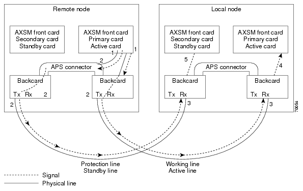
Managing Intercard APS Lines
In AXSM and AXSM/B intercard APS, either front card can be active, and can be connected to either APS line through the APS connector joining the two back cards. The following process describes how intercard APS communication works:
1. The signal leaves the front card at the remote end of the line. (See Figure 1 and Figure 2.)
2. The signal passes through the APS connector and both back card transmit ports at the remote end of the line. (See Figure 1 and Figure 2.)
3. The signal travels through both communication lines to the receive ports on both back cards at the local end. (See Figure 1 and Figure 2.)
4. The active front card processes the signal that is received on the active line. (See Figure 1 and Figure 2.)
5. The standby card monitors only the status of the standby line. (See Figure 1 and Figure 2.)
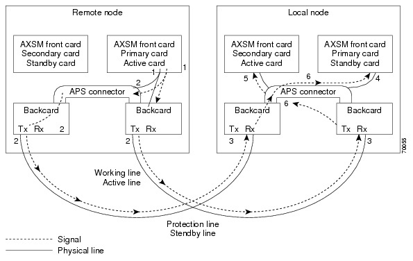
6. If necessary, the signal passes through the APS connector to the front card. (See Figure 2.)
Note The front card monitors only one of the receive lines.
Figure 1 shows an example of how this process operates in a standard APS configuration, where the primary card monitors the working line and the secondary card monitors the protection line.
Figure 2 shows an example of how the APS communication process operates in a crossed APS configuration, where the secondary card monitors the working line that is attached to the primary card, and the primary card monitors the protection line that is connected to the secondary card.
Figure 1
Standard APS Configuration
Figure 2
Crossed APS Configuration
Line failures are always detected at the receive end of the line. This is where a switchover occurs when a failure is detected. Two different types of switchovers can occur, depending on whether the APS was configured as unidirectional or bidirectional in the cnfapsln command:
•When a failure occurs on a line configured for unidirectional switching, the switch changes lines at the receive end only. A switchover is not necessary at the transmit end because the transmitting back cards send signals on both lines in the 1 +1 APS configuration.
•When a failure occurs on a line configured for bidirectional switching, a switchover occurs at both ends of the line.
If the status of the standby line is good, a switchover from the failed active line to the standby is automatic.
Enter the cnfapsln command to enable an automatic switchover back to the working line after it recovers from a failure, as shown in the following example:
M8850_LA.1.AXSM.a > cnfapsln -w 1.1.1 -rv 2
Table 1 describes the configurable parameters for the cnfapsln command.
Table 8 cnfapsln Command Parameters
-w <working line>
|
Slot number, bay number, and line number of the active line to configure, in the format:
Example: -w 1.1.1
|
-sf <signal fault ber>
|
A number between 3 and 5 indicating the Signal Fault Bit Error Rate (BER), in powers of ten:
•3 = 10-3
•4 = 10-4
•5 = 10-5
Example: -sf 3
|
-sd <SignalDegradeBER>
|
A power if 10 in the range 5-9 that indicates the Signal Degrade Bit Error Rate (BER):
•5 = 10-5
•6 = 10-6
•7 = 10-7
•8 = 10-8
•9 = 10-9
Example: -sd 5
|
-wtr <Wait To Restore>
|
The number of minutes to wait after the failed working line has recovered, before switching back to the working line. The range is 5-12.
Example: -wtr 5
|
-dr <direction>
|
Determines whether the line is unidirectional or bidirectional.
•1 = Unidirectional. The line switch occurs at the receive end of the line.
•2 = Bidirectional. The line switch occurs at both ends of the line.
Note This optional parameter is not shown in the above example because you do not need to set it for a revertive line.
Example: -dr 2
|
-rv <revertive>
|
Determines whether the line is revertive or non-revertive.
•1 = Non-revertive. You must manually switch back to a recovered working line.
•2 = Revertive. APS automatically switches back to a recovered working line after the number of minutes set in the -wtr parameter.
Example: -rv 1
|
If you want to manually switch from one line to another, enter the switchapsln <bay> <line> <switchOption> command, as shown in the following example:
M8850_LA.1.AXSM.a > switchapsln 1 1 6
Manual line switch from protection to working succeeded on line 1.1.1
Table 2 describes the configurable parameters for the cnfapsln command.
Table 9 switchapsln Command Parameters
Parameter
|
Description
|
bay
|
The working bay number to switch.
|
line
|
The working line number to switch.
|
switchOption
|
The method of performing the switchover.
•1 = Clear previous user switchover requests. Return to working line only if the mode is revertive.
•2 = Lockout of protection. Prevents specified APS pair from being switched over to the protection line. If the protection line is already active, the switchover is made back to the working line.
•3 = Forced working to protection line switchover. If the working line is active, the switchover is made to the protection line unless the protection line is locked out or in the SF condition, or if a forced switchover is already in effect.
•4 = Forced protection to working line switchover. If the protection line is active, the switch is made to the working line unless a request of equal or higher priority is in effect. This option has the same priority as option 3 (forced working to protection line switchover). Therefor, if a forced working to protection line switchover is in effect, it must be cleared before this option (forced protection to working line switchover) can succeed.
•5 = Manual switchover from working to protection line unless a request of equal or higher priority is in effect.
•6 = Manual switchover from protection to working line. This option is only available in the 1+1 APS architecture.
|
service switch
|
This is an optional parameter. When set to 1, this field causes all APS lines to switch to their protected lines.
|
Enter the dspapslns command to verify that the active line switched over from the protection line to the working line, as shown in the following example:
M8850_LA.1.AXSM.a > dspapslns
Working Prot. Conf Oper Active WLine PLine WTR Revt Conf Oper LastUser
Index Index Arch Arch Line State State (min) Dir Dir SwitchReq
------- ----- ---- ----- ------ ----- ----- ----- ---- ---- ---- ----------
1.1.1 2.1.1 1+1 1+1 working OK OK 5 Yes bi bi ManualP->W
Troubleshooting APS Lines
Port lights on AXSM and AXSM/B front cards indicate the receive status of APS lines. The active front card always displays the status of the active line. The standby card always displays the status of the inactive line. If only one APS line fails, the line failure LED is always displayed on the standby front card.
Caution When the active front card and the active line are in different slots and the inactive line has failed, it is easy to incorrectly identify the failed line as the line in the standby slot. To avoid disrupting traffic through the active line, verify which physical line is at fault before disconnecting the suspect line.
If the active line fails and the standby line is not available, the switch reports a critical alarm.
If the active line fails and the standby line takes over, the former standby line becomes the new active line, and the switch reports a major alarm.
If an AXSM front card fails, APS communication between the redundant front cards fails. This can result in one of the following situations:
•If both APS lines were working before the failure, an APS line failure causes a switchover to the protection line
•If either APS line failed prior to a front card failure, a failure on the active line does not cause a switchover to the other line. Because the standby front card failed, it cannot monitor the standby line and report when the line has recovered. This means that the active card cannot use the standby line until the standby front card is replaced and the line problem corrected.
Use the following procedure to troubleshoot APS lines.
Step 1 Enter the dsplns command to determine if the line in alarm is an APS line. The dsplns command shows which lines are enabled for APS:
M8850_LA.1.AXSM.a > dsplns
Sonet Line Line Line Frame Line Line Alarm APS
Line State Type Lpbk Scramble Coding Type State Enabled
----- ----- ------------ ------ -------- ------ ------- ----- --------
1.1 Up sonetSts12c NoLoop Enable Other ShortSMF Clear Enable
1.2 Up sonetSts12c NoLoop Enable Other ShortSMF Clear Disable
2.1 Up sonetSts12c NoLoop Enable Other ShortSMF Clear Disable
2.2 Up sonetSts12c NoLoop Enable Other ShortSMF Clear Disable
If the line in alarm is an APS line, and has always functioned properly as an APS line, proceed to Step 2.
If the line in alarm has never functioned properly as an APS line, verify that the following are true:
•redundant front and back cards are in the appropriate bays and are installed at both ends of the line.
•cable is properly connected to both ends of the line.
•enter the dspapsbkplane command to verify that the APS connector is installed properly at both ends of the line.
Step 2 Enter the dspapslns command at both ends of the communication line to determine whether one or both lines in an APS pair are bad. Use Table 3 to help you determine which APS line is not functioning properly.
Table 10 Troubleshooting APS Line Problems Using the dspaps Command
Active Line
|
Working Line
|
Protection Line
|
Working Line LED
|
Protection Line
LED
|
Description
|
Working
|
OK
|
OK
|
Green
|
Green
|
Active card is receiving signal on working and protection lines. This does not guarantee that transmit lines are functioning properly. You must view the status on remote switch.
|
Protection
|
SF
|
OK
|
Green
|
Red
|
Active card is receiving signal on the protection line. No signal received on the working line.
|
Working
|
OK
|
SF
|
Green
|
Red
|
Active card is receiving signal on the working line. No signal received on the protection line.
|
Working
|
SF
|
SF
|
Red
|
Red
|
Active card is not receiving signal from either line. The working line was the last line to work.
|
Protection
|
SF
|
SF
|
Red
|
Red
|
Active card is not receiving signal from either line. The protection line was the last line to work.
|
Working
|
UNAVAIL
|
UNAVAIL
|
|
|
The card set is not complete. One or more cards have failed or been removed. See Table 4 to troubleshoot card errors.
|
If one or both lines appear to be bad, determine whether the working or protection line is in alarm. Troubleshoot and correct the standby line first. Replace the components along the signal path until the problem is resolved.
•If the dspapslns command at either end of the line indicates a front or back card problem, resolve that problem first. (See tTable 11 to card problems).
•If the dspapslns command shows a signal failure on the standby line, replace that line.
•If the standby line is still down, replace the cards along the signal path.
Table 11 Troubleshooting Card Problems
APS Line Failure
|
Possible Cause
|
All lines in upper and lower bays
|
Suspect a bad or removed front card. If both front cards are good, both back cards may be bad.
|
All lines in upper bay only. Lower bay APS lines ok.
|
Suspect bad upper bay back card.
|
All lines in lower bay only. Upper bay APS lines OK.
|
Suspect bad lower bay back card.
|
Clearing the Configuration on Redundant PXM45 Cards
Due to checks to prevent an inserted card from affecting the system, an additional step may be required when inserting two "non-native" PXM45 cards in a shelf. Insert the first PXM45, do a clrallcnf, and allow this to become active before inserting the second PXM45.
Recommendations
Cisco Systems provides the following information and recommendations for switch configuration:
•The RPM-PR subinterface ID range is 1 - 32767.
•Apply the default values for PCR, SCR, and so on to the Control VC. If the values are decreased to a low value, there is a chance that the protocol on the interface (SSCOP or PNNI) will not come up.
Installing and Upgrading to Release 2.1.70
You can gracefully upgrade an MGX 8850 to Release 2.1.70 from Release 2.0.15, 2.1.10, or 2.1.60.
The procedures in this section were extracted from "Appendix A, Downloading and Installing Software Upgrades" in the "MGX 8850 Switch Software Configuration Guide, Release 2.1" (part DOC-7812551=). In this section, references to "chapters" refer to chapters in that manual.
You can download that manual from http://www.cisco.com/univercd/cc/td/doc/product/wanbu/8850r21/index.htm.
Caution Although graceful upgrades can be aborted with the abortrev command, the abortrev command does reset both active and standby cards, so reverting back to an earlier software release is not graceful. Please see the "abortrev" command description in the "Cisco MGX 8850 Switch Command Reference, Release 2.1" (part DOC-7812563=). A table under that command shows the behavior of cards in a single and redundant configuration.
This section describes how to locate, download, and install software updates for the switch. Because software updates are stored in the switch file system, this section includes a subsection on browsing the file system. This section includes the following subsections:
•Upgrade Process Overview
•Quickstart Procedures for Software Upgrades
•Browsing the File System
•Copying Software Files to the Switch
•Upgrade Procedures for PXM45 and AXSM Cards
•Upgrade Procedures for RPM-PR Cards
•Troubleshooting Upgrade Problems
Upgrade Process Overview
This section provides a series of quickstart procedures that describe how to perform graceful and non-graceful upgrades to the switch. To perform a graceful upgrade on a switch card, the card must be operating in redundant mode with another switch card of the same type. When performed properly, graceful upgrades have minimal impact on connections in progress and do not interrupt any established connections.
Note Graceful upgrades to Release 2.1.70 are supported from Releases 2.0.15, 2.1.10, and 2.1.60.
When a card to be upgraded is not operating in redundant mode, you must do a non-graceful upgrade, which disrupts all traffic that passes through the card. For PXM45 cards, an ungraceful upgrade interrupts all traffic passing through the switch. For all other types of cards, an ungraceful upgrade affects only the traffic that passes through that card.
Each type of switch card runs boot and runtime software. The recommended sequence for upgrading the software (i.e., firmware) on switch cards is as follows:
1. PXM45 boot software
2. PXM45 runtime software
3. AXSM boot software
4. AXSM runtime software
5. RPM-PR boot software
6. RPM-PR runtime software
Note If you plan to upgrade PXM45 cards and AXSM cards, upgrade the PXM45 cards first. Wait until the PXM45 cards are operating in active and standby modes with the correct software before upgrading AXSM cards. The software version used by the PXM45/B cards should be equal to or later than the version used on the AXSM, AXSM/B, and AXSM-E cards.
Typically, the boot software requires less frequent upgrades. However, in this release, both the boot and runtime software need to be upgraded.
When you upgrade the software on a switch card, proceed as follows:
•Decide whether you are performing a graceful or non-graceful upgrade
•Follow the appropriate quickstart procedure for that type of upgrade
•For additional information on a task within a quickstart procedure, see the subsection to which the procedure refers
The next subsection presents the quickstart procedures for switch card software upgrades.
Quickstart Procedures for Software Upgrades
The following subsections provide quickstart procedures for the following upgrades:
•Graceful PXM45 Boot Upgrades
•Non-Graceful PXM45 Boot Upgrades
•Graceful PXM45 and AXSM Runtime Software Upgrades
•Non-Graceful PXM45 and AXSM Runtime Software Upgrades
•Graceful AXSM Boot Upgrades
•Non-Graceful AXSM Boot Upgrades
•RPM-PR Boot and Runtime Software Upgrades
Caution A CP port session is required because you will be resetting the node and entering commands in "Backup Boot mode," which is not accessible through other connection methods.
Graceful PXM45 Boot Upgrades
When performed properly, graceful upgrades have minimal impact on connections in progress and do not interrupt any established connections.
When a boot software upgrade is required, the procedure for upgrading redundant PXM45 cards updates the standby card and then makes that card active. This method ensures a smooth transition to the new software and preserves all established calls. Any calls that are not established are lost.
A graceful upgrade of the boot software does the following:
1. Loads the new software on the standby PXM45 card
2. Makes the standby PXM45 card active
3. Loads the new software on the formerly active (now standby) PXM45 card
Note Avoid making configuration changes while upgrading PXM45 software. Configuration changes can be lost when the PXM45 is reset during the upgrade.
To upgrade the runtime software, use the following procedure.
| |
Command
|
Purpose
|
Step 1
|
ftp
|
Copy the boot and runtime files you want to use to the switch.
See "Copying Software Files to the Switch," which appears later in this section.
|
Step 2
|
username
password
|
Establish a CLI session with the standby PXM45 card using the CP port on the UI-S3 back card and a user name with CISCO_GP privileges.
|
Step 3
|
saveallcnf
|
This optional step saves the current configuration to the hard disk of the active PXM45/B card. (The command can only be issued on the active PXM card.)
Refer to "Saving a Configuration" in Chapter 7, "Switch Operating Procedures."
|
Step 4
|
sh
sysBackupBoot
<Return> (2.0.11 and earlier)
|
Using the CP port connection, change to the PXM45 Backup Boot mode.
Note that the software versions 2.0.11 and earlier require you to press Return during the reboot sequence to enter backup boot mode.
See "Changing to PXM45 Backup Boot Mode" in Appendix B, "PXM45 Backup Boot Procedures."
|
Step 5
|
sysPxmRemove
|
At the backup boot prompt, enter the sysPxmRemove command: This step prevents the active card from resetting the standby card while you are working with it.
|
Step 6
|
sysFlashBootBurn "Filename"
reboot
username
password
dspcds; dsprevs
|
Burn the boot software. Remember to enter quotation marks before and after the boot software filename. For example:
sysFlashBootBurn "C:FW/pxm45_002.001.070.202_bt.fw"
See "Upgrading PXM45 Boot Software," which appears later in this section.
|
Step 7
|
username
password
|
Establish a CLI session with the active PXM45 card (which is the non-upgraded card) using the CP port on the UI-S3 back card and a user name with CISCO_GP privileges.
|
Step 8
|
switchcc
y
|
Switch the roles of the active and standby cards so you can upgrade the non-upgraded card in standby mode.
|
Step 9
|
sh
sysBackupBoot
<Return> (2.0.11 and earlier)
|
Using the CP port connection, change to the PXM45 Backup Boot mode.
Note that the software versions 2.0.11 and earlier require you to press Return during the reboot sequence to enter backup boot mode.
See "Changing to PXM45 Backup Boot Mode" in Appendix B, "PXM45 Backup Boot Procedures.".
|
Step 10
|
sysPxmRemove
|
At the backup boot prompt, enter the sysPxmRemove command: This step prevents the active card from resetting the standby card while you are working with it.
|
Step 11
|
sysFlashBootBurn "Filename"
reboot
username
password
dspcds; dsprevs
|
Burn the boot software. Remember to enter quotation marks before and after the boot software filename. For example:
sysFlashBootBurn "C:FW/pxm45_002.001.070.202_bt.fw"
See "Upgrading PXM45 Boot Software," which appears later in this section.
The boot software is now upgraded on both the active and standby cards. The card that was active before the upgrade is now operating in standby mode.
|
Non-Graceful PXM45 Boot Upgrades
Ungraceful upgrades disrupt all switch traffic and are usually used in lab installations where the use of standalone cards provides no opportunity for a graceful upgrade. The quickstart procedure is provided as an overview and as a quick reference.
Note Avoid making configuration changes while upgrading PXM45 software. Configuration changes can be lost when the PXM45 is reset during the upgrade.
| |
Command
|
Purpose
|
Step 1
|
ftp
|
Copy the boot and runtime files you want to use to the switch.
See "Copying Software Files to the Switch," which appears later in this section.
|
Step 2
|
username
password
|
Establish a CLI session with the active PXM45 card using the CP port on the UI-S3 back card and a user name with CISCO_GP privileges.
|
Step 3
|
saveallcnf
|
This optional step saves the current configuration to the hard disk of the active PXM45/B card.
Refer to "Saving a Configuration" in Chapter 7, "Switch Operating Procedures."
|
Step 4
|
sh
sysBackupBoot
<Return> (2.0.11 and earlier)
|
Using the CP port connection, change to the PXM45 Backup Boot mode.
Note that the software versions 2.0.11 and earlier require you to press Return during the reboot sequence to enter backup boot mode.
See "Changing to PXM45 Backup Boot Mode" in Appendix B, "PXM45 Backup Boot Procedures."
|
Step 5
|
sysFlashBootBurn "Filename"
reboot
username
password
dspcd; dsprevs
|
Burn the boot software. Remember to enter quotation marks before and after the boot software filename. For example:
sysFlashBootBurn "C:FW/pxm45_002.001.070.202_bt.fw"
See "Upgrading PXM45 Boot Software," which appears later in this section.
|
Graceful PXM45 and AXSM Runtime Software Upgrades
When performed properly, graceful upgrades have minimal impact on connections in progress and do not interrupt any established connections.
This quickstart procedure applies to both PXM45 and AXSM cards and does the following:
1. Loads the new software on the standby PXM45 or AXSM card
2. Makes the standby card active
3. Loads the new software on the formerly active (now standby) card
Note If you plan to upgrade PXM45 cards and AXSM cards, upgrade the PXM45 cards first. Wait until the PXM45 cards are operating in active and standby modes with the correct software before upgrading AXSM cards. The software version used by the PXM45/B cards should be equal to or later than the version used on the AXSM, AXSM/B, and AXSM-E cards. When AXSM boot software is to be upgraded, it should be upgraded before upgrading the runtime software.
Note Avoid making configuration changes while upgrading PXM45 software. Configuration changes can be lost when the PXM45 is reset during the upgrade.
Note Upgrade software on the node to Release 2.1.70 before inserting the AXSM-E card.
To upgrade the runtime software, use the following procedure.
| |
Command
|
Purpose
|
Step 1
|
ftp
|
Copy the boot and runtime files you want to use to the switch.
See "Copying Software Files to the Switch," which appears later in this section.
|
Step 2
|
|
Upgrade the boot software for the card you are upgrading.
PXM45 cards should be upgraded first. See "Graceful PXM45 Boot Upgrades," which appears earlier in this section.
For instructions on upgrading AXSM boot software, see "Graceful AXSM Boot Upgrades," which appears later in this section.
|
Step 3
|
username
password
|
Establish a CLI session with the active PXM45 card using a user name with SERVICE_GP privileges.
|
Step 4
|
saveallcnf
|
This optional step saves the current configuration to the hard disk of the active PXM45/B card.
Refer to "Saving a Configuration" in Chapter 7, "Switch Operating Procedures."
|
Step 5
|
dspcds; dsprevs; dsprev -sl
commitrev <slot> <revision>
|
Verify that all previous upgrades have been committed.
If a previous upgrade has not been committed, commit to the new upgrade.
See "Committing to a Runtime Software Upgrade," which appears later in this section.
|
Step 6
|
loadrev <slot> <revision>
dspcds; dsprev -sl
|
Load the new runtime software on the standby card.
|
Step 7
|
runrev <slot> <revision>
dspcds; dsprev -sl
dspcd <slot>
|
Switch over to the standby card and load the new runtime software on the new standby (non-upgraded) card.
|
Step 8
|
commitrev <slot> <revision>
dspcds
dsprevs
dsprev -sl
|
This command prevents an accidental switch back to a previous software revision if someone enters the abortrev command. Enter the commitrev command after the former active card comes up in the standby-U state. Cisco Systems recommends that you avoid configuration changes until after you have run the commitrev or abortrev commands.
See "Aborting a Runtime Software Upgrade" and "Committing to a Runtime Software Upgrade," both of which appear later in this section.
|
Non-Graceful PXM45 and AXSM Runtime Software Upgrades
Ungraceful upgrades disrupt all switch traffic and are usually used in lab installations where the use of standalone cards provides no opportunity for a graceful upgrade. The quickstart procedure is provided as an overview and as a quick reference.
Note If you plan to upgrade PXM45 cards and AXSM cards, upgrade the PXM45 cards first. Wait until the PXM45 cards are operating in active and standby modes with the correct software before upgrading AXSM cards. The software version used by the PXM45/B cards should be equal to or later than the version used on the AXSM, AXSM/B, and AXSM-E cards. When AXSM boot software is to be upgraded, it should be upgraded before upgrading the runtime software.
Note Avoid making configuration changes while upgrading PXM45 software. Configuration changes can be lost when the PXM45 is reset during the upgrade.
Note Upgrade software on the node to Release 2.1.70 before inserting the AXSM-E card.
| |
Command
|
Purpose
|
Step 1
|
ftp
|
Copy the boot and runtime files you want to use to the switch.
See "Copying Software Files to the Switch," which appears later in this section.
|
Step 2
|
|
Upgrade the boot software as described in "Non-Graceful PXM45 Boot Upgrades," which appears earlier in this section or "Non-Graceful AXSM Boot Upgrades," which appears later in this section.
|
Step 3
|
username
password
|
Establish a CLI session with the active PXM45 card using a user name with SERVICE_GP privileges.
|
Step 4
|
saveallcnf
|
This optional step saves the current configuration to the hard disk of the active PXM45/B card.
Refer to "Saving a Configuration" in Chapter 7, "Switch Operating Procedures."
|
Step 5
|
dspcds; dsprev -sl
commitrev <slot> <revision>
|
Verify that all previous upgrades have been committed.
If a previous upgrade has not been committed, commit to the new upgrade.
See "Committing to a Runtime Software Upgrade," which appears later in this section.
|
Step 6
|
loadrev <slot> <revision>
dspcds; dsprev -sl
|
Define the new software version to be used.
|
Step 7
|
runrev <slot> <revision>
dspcds; dsprev -sl
|
Reset the card and run the new runtime software version.
|
Step 8
|
commitrev <slot> <revision>
dspcds
dsprev -sl
dsprevs
|
This command prevents an accidental switch back to a previous software revision if someone enters the abortrev command.
Cisco Systems recommends that you avoid configuration changes until after you have run the commitrev or abortrev commands.
See "Aborting a Runtime Software Upgrade" and "Committing to a Runtime Software Upgrade," both of which appear later in this section.
|
Graceful AXSM Boot Upgrades
When performed properly, graceful upgrades have minimal impact on connections in progress and do not interrupt any established connections. The quickstart procedure is provided as an overview and as a quick reference.
Note If you plan to upgrade PXM45 cards and AXSM cards, upgrade the PXM45 cards first. Wait until the PXM45/B cards are operating in active and standby modes with the correct software before upgrading AXSM cards. The software version used by the PXM45/B cards should be equal to or later than the version used on the AXSM, AXSM/B, and AXSM-E cards.
Note Upgrade software on the node to Release 2.1.70 before inserting the AXSM-E card.
| |
Command
|
Purpose
|
Step 1
|
ftp
|
Copy the boot and runtime files you want to use to the switch.
See "Copying Software Files to the Switch," which appears later in this section.
|
Step 2
|
username
password
|
Establish a CLI session with the active PXM45 card using a user name with SERVICE_GP privileges or higher.
|
Step 3
|
saveallcnf
|
This optional step saves the current configuration to the hard disk of the active PXM45/B card.
Refer to "Saving a Configuration" in Chapter 7, "Switch Operating Procedures."
|
Step 4
|
burnboot <slot> <revision>
dspcd <slot>
dsprevs
|
Burn the boot software on the standby AXSM card by specifying the slot number of the standby card.
See "Upgrading Boot Software on an AXSM Card," which appears later in this section.
|
Step 5
|
switchredcd <fromSlot> <toSlot>
|
Activate the upgraded card and place the non-upgraded card in standby mode.
|
Step 6
|
burnboot <slot> <revision>
dspcd <slot>
dsprevs
|
Burn the boot software on the non-upgraded, standby AXSM card by specifying the slot number of the standby card.
See "Upgrading Boot Software on an AXSM Card," which appears later in this section.
|
Non-Graceful AXSM Boot Upgrades
Ungraceful upgrades disrupt all switch traffic and are usually used in lab installations where the use of standalone cards provides no opportunity for a graceful upgrade. The quickstart procedure is provided as an overview and as a quick reference.
Note If you plan to upgrade PXM45 cards and AXSM cards, upgrade the PXM45 cards first. Wait until the PXM45 cards are operating in active and standby modes with the correct software before upgrading AXSM cards. The software version used by the PXM45/B cards should be equal to or later than the version used on the AXSM, AXSM/B, and AXSM-E cards.
Note Upgrade software on the node to Release 2.1.70 before inserting the AXSM-E card.
| |
Command
|
Purpose
|
Step 1
|
ftp
|
Copy the boot and runtime files you want to use to the switch.
See "Copying Software Files to the Switch," which appears later in this section.
|
Step 2
|
username
password
|
Establish a CLI session with the active PXM45 card using a user name with SERVICE_GP privileges or higher.
|
Step 3
|
saveallcnf
|
This optional step saves the current configuration to the hard disk of the active PXM45 card.
Refer to "Saving a Configuration" in Chapter 7, "Switch Operating Procedures."
|
Step 4
|
burnboot <slot> <revision>
dspcd <slot>
dsprevs
|
Burn the boot software on the standby AXSM card by specifying the slot number of the standby card.
See "Upgrading Boot Software on an AXSM Card," which appears later in this section.
|
RPM-PR Software Upgrades for Cards with 1:N Redundancy
On the MGX 8850, the RPM cards can go into slots 1 through 6, or 9 through 14.
The RPM-PR card supports software upgrades when 1:N redundancy is established in the switch between RPM-PR cards. Boot software is generally upgraded less often than runtime software, so be sure to compare the recommended boot software version with the boot software running on your RPMs before starting an upgrade. The correct boot software might already be installed.
The following quickstart procedure describes how to upgrade redundant RPM-PR cards. For detailed instructions, see "Upgrade Procedures for RPM-PR Cards," which appears later in this section.
These procedures describe how to upgrade boot as well as runtime software together or runtime software only.
Note Redundancy must be established before you use this procedure. If redundancy has not been configured between two RPM-PR cards, upgrade each RPM-PR card using the procedure in "RPM-PR Software Upgrades for Non-Redundant Cards," which appears later in this chapter. To add redundancy to an RPM-PR card, refer to "Establishing Redundancy Between Two RPM-PR Cards" in Chapter 4, "Preparing RPM-PR Cards for Operation."
Table 12
| |
Command
|
Purpose
|
Step 1
|
ftp
|
Copy the boot and runtime files you want to use to the switch (E:RPM).
See "Copying Software Files to the Switch," which appears later in this section.
|
Step 2
|
username
password
|
Establish a CLI session with the active PXM45 card using a user name at any access level.
|
Step 3
|
cc <primarySlot>
|
Select the slot in which the primary RPM-PR card is installed.
|
Step 4
|
enable
password
|
Enter Enable mode for the router.
|
Step 5
|
dir e:
|
Verify router access to the PXM45 hard disk and the boot upgrade software.
|
Step 6
|
show flash:
|
Display current contents of bootflash.
|
Step 7 S
|
copy filename bootflash:
dir bootflash:
|
Copy the upgrade boot software to flash. For example:
copy e:rpm-boot-mz_002.001.060.000 bootflash:
|
Step 8
|
del bootflash:
|
Delete older boot files from the bootflash. The switch always attempts to load the first bootable file in bootflash. If the upgraded file has a higher file number than another bootable file, it will not be used when the card is reset.
Note This step marks files to be deleted, but it does not delete them.
|
Step 9
|
show flash:
|
Caution Verify that at least one valid boot or runtime image will not be deleted. If all boot and runtime images are deleted from bootflash, the RPM card must be returned to the factory for repair.
|
Step 10
|
squeeze flash:
|
This step deletes all files that have been marked for deletion.
|
Step 11
|
copy
|
Optional: Copy and rename the runtime file to a generic name for easy updates.
See "Non-Graceful RPM-PR Runtime Software Upgrades," which appears later in this chapter.
Note If you have already configured the RPM to use a generic name, you can skip to Step 12.
|
Step 12
|
show bootvar
|
Display the current runtime software filename.
|
Step 13
|
config terminal
|
Enter the router global configuration mode.
|
Step 14
|
no boot system
|
Remove the entire boot list. To remove a single file from the boot list, include a filename. For example:
Router(config)# no boot system c:rpm-js-mz_122-4.T
|
Step 15
|
boot system c:filename
|
Add the new router runtime image to the boot list. For example:
Router(config)# boot system c:rpm-js-mz_122-4.T
|
Step 16
|
boot config e:auto_config_RPM-PR_slot#
|
Configure the RPM-PR card to store its configuration on the PXM45 hard disk.
Note This step only needs to be performed once. If this command is already in the startup configuration file, you do not need to enter it again.
|
Step 17
|
^Z
|
Exit global configuration mode.
|
Step 18
|
copy run start
|
Save the new configuration.
Note If you omit this step, the RPM-PR card will continue to use the previous version of software.
|
Step 19
|
show bootvar
|
Verify the change in the runtime software filename.
|
Step 20
|
softswitch <primarySlot> <secondarySlot>
|
This step makes the secondary card active and resets the primary RPM-PR card. When the primary card resets, it loads the upgraded boot software from bootflash.
|
Step 21
|
cc <secondarySlot>
|
Select the slot in which the secondary RPM-PR card is installed.
|
Step 22
|
enable
password
dir e:
show flash:
copy filename bootflash:
dir bootflash:
show flash:
squeeze flash:
|
Repeat Step 4 through Step 10 to move the upgraded boot software into bootflash.
|
Step 23
|
show bootvar
config terminal
no boot system
boot system c:filename
^Z
copy run start
show bootvar
|
Repeat Step 12 through Step 15 andStep 17 through Step 19 to upgrade runtime software.
|
Step 24
|
softswitch <secondarySlot> <primarySlot>
|
This step makes the upgraded primary card active and resets the secondary RPM-PR card. When the secondary card resets, it loads the upgraded boot software from bootflash. Both primary and secondary cards should now be using upgraded boot software.
|
Step 25
|
|
If there are other primary RPM-PR cards that need upgrading, repeat the part of this procedure that upgrades the primary card, then execute the softswitch command once to reload the primary card. Finally, execute the softswitch command a second time to make the upgraded primary card active.
|
RPM-PR Boot Software and Runtime Software Upgrades Together
RPM-PR Runtime Software Upgrade (no boot software upgrade)
The RPM-PR card supports upgrades when 1:N redundancy is established in the switch between RPM-PR cards.
The following quickstart procedure describes how to gracefully upgrade redundant RPM-PR cards.
Note Redundancy must be established before you use this procedure. If redundancy has not been configured between two RPM-PR cards, upgrade each RPM-PR card as described in "RPM-PR Runtime Software Upgrades for Non-Redundant Cards," which appears later in this chapter. To add redundancy to an RPM-PR card, refer to "Establishing Redundancy Between Two RPM-PR Cards" in Chapter 4, "Preparing RPM-PR Cards for Operation."
Table 13
| |
Command
|
Purpose
|
Step 1
|
ftp
|
Copy the boot and runtime files you want to use to the switch (E:RPM).
See "Copying Software Files to the Switch," which appears later in this section.
|
Step 2
|
copy
|
Optional: Copy and rename the runtime file to a generic name for easy updates.
See "Non-Graceful RPM-PR Runtime Software Upgrades," which appears later in this chapter.
Note If you have already configured the RPM to use a generic name, you can skip to Step 12.
|
Step 3
|
username
password
|
Establish a CLI session with the active PXM45 card using a user name at any access level.
|
Step 4
|
cc <primarySlot>
|
Select the slot in which the primary RPM-PR card is installed.
|
Step 5 .
|
enable
password
|
Enter Enable mode for the router.
|
Step 6
|
show bootvar
|
Display the current runtime software filename.
|
Step 7
|
config terminal
|
Enter the router global configuration mode.
|
Step 8
|
no boot system
|
Remove the entire boot list. To remove a single file from the boot list, include a filename. For example:
Router(config)# no boot system c:rpm-js-mz_122-4.T
|
Step 9
|
boot system c:filename
|
Add the new router runtime image to the boot list. For example:
Router(config)# boot system c:rpm-js-mz_122-4.T
|
Step 10
|
boot config e:auto_config_RPM-PR_slot#
|
Configure the RPM-PR card to store its configuration on the active PXM45 hard disk.
Note This step only needs to be performed once. If this command is already in the startup configuration file, you do not need to enter it again.
|
Step 11
|
^Z
|
Exit global configuration mode.
|
Step 12
|
copy run start
|
Save the new configuration.
Note If you omit this step, the RPM-PR card will continue to use the previous version of software.
|
Step 13
|
show bootvar
|
Verify the change in the runtime software filename.
|
Step 14
|
softswitch <primarySlot> <secondarySlot>
|
This step makes the secondary card active and resets the primary RPM-PR card. When the primary card resets, it loads the upgraded boot software from bootflash.
|
Step 15
|
cc <secondarySlot>
|
Select the slot in which the secondary RPM-PR card is installed.
|
Step 16
|
enable
password
show bootvar
config terminal
no boot system
boot system c:filename
^Z
copy run start
show bootvare
|
Repeat Step 5 through Step 9 and Step 11 through Step 13.
|
Step 17
|
softswitch <secondarySlot> <primarySlot>
|
This step makes the upgraded primary card active and resets the secondary RPM-PR card. When the secondary card resets, it loads the upgraded boot software from bootflash. Both primary and secondary cards should now be using upgraded runtime software.
|
Step 18
|
|
If there are other primary RPM-PR cards that need upgrading, repeat the part of this procedure that upgrades the primary card, then execute the softswitch command once to reload the primary card. Finally, execute the softswitch command a second time to make the upgraded primary card active.
|
RPM-PR Runtime Software Upgrade (no boot upgrade)
RPM-PR Software Upgrades for Non-Redundant Cards
Use the software upgrade procedure in this subsection when you need to upgrade RPM-PR boot software and the RPM-PR is operating in standalone mode.
Note If the RPM-PR is operating in 1:N redundancy mode with another RPM-PR, upgrade the cards as described in "RPM-PR Software Upgrades for Cards with 1:N Redundancy," which appears earlier in this chapter.
The following quickstart procedure is provided as an overview and as a quick reference for those who have already performed RPM-PR upgrades on the switch. For detailed instructions, see "Upgrade Procedures for RPM-PR Cards," which appears later in this section.
Table 14
| |
Command
|
Purpose
|
Step 1
|
ftp
|
Copy the boot and runtime files you want to use to the switch (E:RPM).
See "Copying Software Files to the Switch," which appears later in this section.
|
Step 2
|
username
password
|
Establish a CLI session with the active PXM45 card using a user name at any access level.
|
Step 3
|
cc <RPM-PR_Slot>
|
Select the slot in which the RPM-PR card is installed.
|
Step 4
|
enable
password
|
Enter Enable mode for the router.
|
Step 5
|
dir e:
|
Verify router access to the active PXM45 hard disk and the boot upgrade software.
|
Step 6
|
show flash:
|
Display current contents of bootflash.
|
Step 7 S
|
copy filename bootflash:
dir bootflash:
|
Copy the upgrade boot software to flash. For example:
copy e:rpm-boot-mz_002.001.070.202 bootflash:
|
Step 8
|
del bootflash:
|
Optional. Delete older boot files from the bootflash. This step marks files to be deleted, but it does not delete them.
|
Step 9
|
show flash:
|
Caution Verify that at least one valid boot or runtime image will not be deleted. If all boot and runtime images are deleted from bootflash, the RPM card must be returned to the factory for repair.
|
Step 10
|
squeeze flash:
|
This step deletes all files that have been marked for deletion.
|
Step 11
|
show bootvar
|
Display the current runtime software filename.
|
Step 12
|
config terminal
|
Enter the router global configuration mode.
|
Step 13
|
no boot system
|
Remove the entire boot list. To remove a single file from the boot list, include a filename. For example:
Router(config)# no boot system c:rpm-js-mz_122-4.T
|
Step 14
|
boot system e:filename
|
Add the new router runtime image to the boot list. For example:
Router(config)# boot system e:rpm-js-mz.122-4.T
|
Step 15
|
boot config e:auto_config_RPM-PR_slot#
|
Configure the RPM-PR card to store its configuration on the PXM45 hard disk.
Note This step only needs to be performed once. If this command is already in the startup configuration file, you do not need to enter it again.
|
Step 16
|
^Z
copy run start
|
Exit global configuration mode and save the new configuration.
|
Step 17
|
show bootvar
|
Verify the change in the runtime software filename.
|
Step 18
|
cc <active_PXM45_slot>
resetcd <RPM-PR_Slot>
|
This command sequence restarts the RPM-PR card with the new boot image.
|
RPM-PR Boot and Runtime Software Upgrade (Together)
RPM-PR Runtime Software Upgrades (no boot software upgrade)
Use the software upgrade procedure in this section when you need to upgrade RPM-PR runtime software and the RPM-PR is operating in standalone mode.
Note If the RPM-PR is operating in 1:N redundancy mode with another RPM-PR, upgrade the cards as described in "RPM-PR Software Upgrades for Cards with 1:N Redundancy," which appears earlier in this chapter.
The following quickstart procedure is provided as an overview and as a quick reference for those who have already performed RPM-PR upgrades on the switch. For detailed instructions, see "Upgrade Procedures for RPM-PR Cards," which appears later in this section.
Table 15
| |
Command
|
Purpose
|
Step 1
|
ftp
|
Copy the boot and runtime files you want to use to the switch (E:RPM).
See "Copying Software Files to the Switch," which appears later in this section.
|
Step 2
|
copy
|
Copy and rename the runtime file to a generic name for easy updates.
See "Non-Graceful RPM-PR Runtime Software Upgrades," which appears later in this chapter.
Note If you have already configured the RPM to use a generic name, you can skip to Step 12.
|
Step 3
|
username
password
|
Establish a CLI session with the active PXM45 card using a user name at any access level.
|
Step 4
|
cc <RPM-PR_Slot>
|
Select the slot in which the RPM-PR card is installed.
|
Step 5
|
enable
password
|
Enter Enable mode for the router.
|
Step 6
|
show bootvar
|
Display the current runtime software filename.
|
Step 7
|
config terminal
|
Enter the router global configuration mode.
|
Step 8
|
no boot system
|
Remove the entire boot list. To remove a single file from the boot list, include a filename. For example:
Router(config)# no boot system c:rpm-js-mz_122-4.T
|
Step 9
|
boot system e:filename
|
Add the new router runtime image to the boot list. For example:
Router(config)# boot system e:rpm-js-mz.122-4.T
|
Step 10
|
boot config e:auto_config_RPM-PR_slot#
|
Configure the RPM-PR card to store its configuration on the PXM45 hard disk.
Note This step only needs to be performed once. If this command is already in the startup configuration file, you do not need to enter it again.
|
Step 11
|
^Z
copy run start
|
Exit global configuration mode and save the new configuration.
|
Step 12
|
show bootvar
|
Verify the change in the runtime software filename.
|
Step 13
|
cc <active_PXM45_slot>
resetcd <RPM-PR_Slot>
|
This command sequence selects the active PXM card and restarts the RPM card with the new runtime image.
|
Step 14
|
dspcds
dspcd <RPM-PR_Slot>
cc <RPM-PR_Slot>
|
Verify router reboot is complete.
|
RPM-PR Runtime Software Upgrades (no boot software upgrade)
Browsing the File System
The active PXM45 hard disk stores log files, configuration files, and boot and runtime software. The switch operating system supports a set of UNIX-like commands that you can use to locate log files or manage software updates. Table 16 lists commands that you can use to browse the file system.
Note File and directory names in the switch file system are case sensitive. Also, some of the commands listed in Table 16 are not available at all administrator access levels.
Table 16 File System Commands at Switch Prompt
Command
|
Description
|
cd
|
Change directories. Access level required: ANYUSER or above.
|
copy
|
Copies a file from one location to another.
Syntax: copy <source file name> <destination file name>
Access level required: GROUP1 or above.
|
del
|
Deletes a file.
Syntax: del <file name>
Access level required: GROUP1 or above.
|
ll
|
List directory contents using long format, which includes the name, size, modification date, and modification time for each file. This command also displays the total disk space and free disk space.
Syntax: ll
Access level required: ANYUSER or above.
|
ls
|
List directory contents using the short format, which displays filenames, total disk space, and free disk space.
Syntax: ls
Access level required: ANYUSER or above.
|
pwd
|
Display the present working directory.
Syntax: pwd
Access level required: ANYUSER or above.
|
rename
|
Renames a file.
Syntax: rename <old file name> <new file name>
Access level required: GROUP1 or above.
|
whoami
|
Lists the login name for the current session.
Syntax: whoami
Access level required: ANYUSER or above.
|
Copying Software Files to the Switch
This section describes how to copy software files to the MGX 8850 switch. The switch cards use boot software and runtime software. Each PXM45 and AXSM card uses the boot software to define communications between the card components and to enable cards to start up. The runtime software defines how the card operates after startup. RPM-PR cards function on the runtime software and use the boot software only when they cannot load the runtime software.
Note The boot and runtime software are installed on the switch at the factory. Before you copy new files to the switch, verify that you need to update the files by comparing the file versions on the disk to the file versions in Table 2.
The MGX 8850 switches provide a File Transfer Protocol (FTP) service to support file transfers to the switch. If you have FTP client software and network connectivity to both the switch and the server where the software files are stored, you can use FTP to transfer files directly from the server to the switch.
Note The following procedure describes how to copy files to the switch when the runtime software is up and running (showing the node name switch prompt). When the runtime software cannot load, copy the software files to the switch as described in "Transferring Software Files to and from the Switch" in Appendix B, "PXM45 Backup Boot Procedures."
Step 1 Locate the files you want to download from http://www.cisco.com/kobayashi/sw-center/sw-wan.shtml.
Step 2 Using a workstation with FTP client software, transfer PXM45 and AXSM files from the server to the switch directory C:/FW.
The procedure you use for transferring the files depends on the FTP client software you are using. When initiating the FTP connection, remember the following:
•Select the switch by entering its IP address.
•When prompted for a username and password, enter the username and password you use when managing the switch.
•When configuring file transfer options, select binary mode for the file transfer.
Step 3 To verify that the new PXM45 and AXSM files have been transferred to the switch, log into the switch and display the contents of the C:/FW directory.
Step 4 Using a workstation with FTP client software, transfer RPM-PR files from the server to the switch directory E:/RPM.
Note You must use a capital E when referencing the E drive in switch commands.
Step 5 To verify that the new RPM-PR files have been transferred to the switch, log into the switch and display the contents of the e:/RPM directory.
For more information on browsing the switch file system, see "Browsing the File System," which appears earlier in this section.
Upgrade Procedures for PXM45 and AXSM Cards
The following sections describe procedures that support upgrades to PXM45 and AXSM cards. For complete upgrade procedures, see "Quickstart Procedures for Software Upgrades," which appears earlier in this section. The procedures in this section detail some of the tasks listed in the quickstart procedures.
Upgrading PXM45 Boot Software
This section describes how to upgrade the PXM45 boot software on a single PXM45 card. If you are performing a graceful upgrade, use the quickstart procedure described in "Graceful PXM45 Boot Upgrades," which appears earlier in this section. The following procedure provides detailed information on the upgrade task within the quickstart procedure.
Step 1 If you have not done so already, establish a CLI session with the active PXM45 card using the CP port on the UI-S3 back card and a user name with CISCO_GP privileges.
Step 2 If you have not done so already, change to PXM45 Backup Boot mode as described in "Changing to PXM45 Backup Boot Mode" in Appendix B, "PXM45 Backup Boot Procedures.".
Step 3 To burn the boot software on the PXM45, enter the sysFlashBootBurn command as follows:
pxm45bkup> sysFlashBootBurn "filename"
Replace filename with the complete path to the boot file on the PXM45 hard drive. For example:
pxm45bkup> sysFlashBootBurn "C:FW/pxm45_002.001.070.202_bt.fw"
Step 4 When the switch prompts you to confirm this action, type y and press Return.
When the boot software burning process is complete, the switch displays a message similar to the following:
Flash download completed ...
Step 5 When the boot software has been burned, reset the card with the reboot command. For example:
Be patient and wait for Login prompt to appear.
Step 6 When the Login prompt appears, log in to the switch as you do at the beginning of a CLI session. The switch prompt should appear.
Step 7 To confirm that the PXM45 card is now using the correct boot software, enter the dsprevs command.
Step 8 Use dspcd to see the condition of the PXM45 card. You should see active/active and no card alarm.
The Boot FW Rev row in the display should show the new revision as shown in the following example:
8850_NY System Rev: 02.01 Mar. 04, 2001 22:47:23 PST
Slot Number 7 Redundant Slot: 8
Front Card Upper Card Lower Card
---------- ---------- ----------
Inserted Card: PXM45 UI Stratum3 PXM HardDiskDrive
Reserved Card: PXM45 UI Stratum3 PXM HardDiskDrive
State: Active Active Active
Serial Number: SBK050302AF SBK045203PJ SBK044602HJ
Prim SW Rev: 2.0(13) --- ---
Sec SW Rev: 2.0(13) --- ---
Cur SW Rev: 2.0(13) --- ---
Boot FW Rev: 2.1(0) --- ---
800-level Part#: 800-06147-08 800-05787-02 800-05052-04
CLEI Code: BAA670YCAA BA7IBCLAAA BA7IADNAAA
Reset Reason: On Power up
Miscellaneous Information:
Type <CR> to continue, Q<CR> to stop:
After you confirm the upgrade to the first PXM45 card, the boot software upgrade for that card is complete.
Loading the Runtime Upgrade Software
This section describes how to load the runtime upgrade software in preparation for running it. Production switches should have redundant cards installed, so that upgrades can occur without interrupting traffic. For graceful upgrades, the upgrade software is loaded on the standby card first, and then the control is switched to upgraded card so that the other card can be upgraded. The best way to assess the upgrade status of a card is to enter the dspcd <slot> (or dsprev -sl) command. For example:
8850_NY System Rev: 02.01 Mar. 04, 2001 22:47:23 PST
Slot Number 7 Redundant Slot: 8
Front Card Upper Card Lower Card
---------- ---------- ----------
Inserted Card: PXM45 UI Stratum3 PXM HardDiskDrive
Reserved Card: PXM45 UI Stratum3 PXM HardDiskDrive
State: Active Active Active
Serial Number: SBK050302AF SBK045203PJ SBK044602HJ
Prim SW Rev: 2.0(13) --- ---
Sec SW Rev: 2.0(13) --- ---
Cur SW Rev: 2.0(13) --- ---
Boot FW Rev: 2.1(0) --- ---
800-level Part#: 800-06147-08 800-05787-02 800-05052-04
CLEI Code: BAA670YCAA BA7IBCLAAA BA7IADNAAA
Reset Reason: On Power up
Miscellaneous Information:
Type <CR> to continue, Q<CR> to stop:
The primary (Prim SW Rev), secondary (Sec SW Rev), and current (Cur SW Rev) software revision labels indicate the status of an upgrade. In this example, these numbers match because the runtime software upgrade has not started. (Note that the boot software has been upgraded as indicated by the Boot FW Rev label.)
The primary software revision indicates which revision a card will run if it becomes active, and the secondary revision indicates an alternate revision that the card will use if the abortrev command is entered. (For more information on aborting an upgrade, see "Aborting a Runtime Software Upgrade," which appears later in this section.) The current software revision represents the software the active card is using.
The normal sequence of commands for a runtime software upgrade is loadrev, runrev, and commitrev. Table 17 shows how the software revision levels change during a graceful runtime software upgrade. Software Versions Reported During Graceful Upgrades
Table 17 Software Versions Reported During Graceful Upgrades
Software Revision
|
Before Upgrade
|
After loadrev
|
After runrev
|
After commitrev
|
Slot 7
|
Slot 8
|
Slot 7
|
Slot 8
|
Slot 7
|
Slot 8
|
Slot 7
|
Slot 8
|
Active
|
Standby
|
Active
|
Standby
|
Standby
|
Active
|
Active
|
Standby
|
Primary
|
2.0(13)
|
2.0(13)
|
2.0(13)
|
2.0(13)
|
2.1(0)
|
2.1(0)
|
2.1(0)
|
2.1(0)
|
Secondary
|
2.0(13)
|
2.0(13)
|
2.1(0)
|
2.1(0)
|
2.0(13)
|
2.0(13)
|
2.1(0)
|
2.1(0)
|
Current
|
2.0(13)
|
2.0(13)
|
2.0(13)
|
2.1(0)
|
2.1(0)
|
2.1(0)
|
2.1(0)
|
2.1(0)
|
For non-graceful upgrades, the load process defines the software version to which the switch is about to be upgraded. Table 18 shows how the revision levels change during a non-graceful upgrade.
Table 18 Software Versions Reported During Non-Graceful Upgrades
Software Revision
|
Before Upgrade
|
After loadrev
|
After runrev
|
After commitrev
|
Primary
|
2.0(13)
|
2.0(13)
|
2.1(0)
|
2.1(0)
|
Secondary
|
2.0(13)
|
2.1(0)
|
2.0(13)
|
2.1(0)
|
Current
|
2.0(13)
|
2.0(13)
|
2.1(0)
|
2.1(0)
|
If you are performing a graceful upgrade, use the quickstart procedure described in "Graceful PXM45 and AXSM Runtime Software Upgrades," which appears earlier in this section. The following procedure provides detailed information on the load task within the quickstart procedure.
Step 1 To load the upgrade runtime software version on a PXM45 or AXSM card, enter the following command:
mgx8850a.7.PXM.a > loadrev <slot> <revision>
Replace <slot> with the card slot number for the card to be upgraded, and replace <revision> with the software version number for the update. For graceful upgrades, you can specify either the active or the standby card. The switch software will automatically load the upgrade runtime software on the standby card when it is installed. The following example shows how to enter this command:
mgx8850a.7.PXM.a > loadrev 7 2.1(0)
After you enter the loadrev command, the standby card comes up in the standby-U state.
You can find the software version number in Table 2. You can also determine the version number from the runtime software filename as described in "Determining the Software Version Number from Filenames," which appears in Chapter 7, "Switch Operating Procedures."
Step 2 When prompted to confirm the command, type y and press Return to continue.
Step 3 To verify that the load command was processed correctly, enter the dspcd <slot> command and check the status of the software revision levels. You can also view the revision levels with the dsprevs or dsprev -sl command. (dsprev -sl shows that loadrev is done.)
Note In a standalone configuration, the switch does not start the upgraded runtime software until the runrev command is entered. In a redundant configuration, the switch starts the upgraded runtime software on the standby card. The standby card does not become active until the runrev command is entered.
Activating the Upgraded Runtime Software
After you load the upgraded runtime software for a PXM45 or AXSM card, enter the runrev command to start using the software. The version levels for graceful and non-graceful upgrades change as shown earlier in Table 17 and Table 18. The following procedure describes how to activate the upgraded runtime software.
Step 1 To start using the new runtime software version on a PXM45 or AXSM card, enter the following command:
mgx8850a.7.PXM.a > runrev <slot> <revision>
Replace <slot> with the card slot number, and replace <revision> with the software version number specified with the loadrev command. For graceful upgrades, you can specify either the active or the standby card. The switch software will automatically run the upgrade runtime software on the standby card when it is installed. The following example shows how to enter this command:
mgx8850a.7.PXM.a > runrev 7 2.1(0)
The active card is reset, and the former standby card comes up in the active-U state.
Step 2 When prompted to confirm the command, type y and press Return to continue.
Step 3 To verify that the load command was processed correctly, enter the dspcd <slot> command and check the status of the software revision levels. You can also view the revision levels with the dsprev -sl command.
Step 4 When the former active PXM45 comes up in the standby-U state, enter the commitrev command to commit to that software version. This step is optional. The dsprev -sl command shows that runrev is done.
After the runrev command is entered, the switch starts running the new runtime software revision. The secondary software revision shows that a previous revision is still available. Whenever the secondary runtime software revision is different from the primary and current runtime software revisions, you can revert back to the secondary software revision as described in "Aborting a Runtime Software Upgrade," which appears later in this section.
Upgrading Boot Software on an AXSM Card
Note The AXSM upgrade procedures are the same for AXSM, AXSM/B, and the new AXSM-E cards.
The upgrade procedure for the boot software on a single AXSM card is the same for graceful and non-graceful upgrades. The difference between the graceful and non-graceful boot software upgrades is the sequence of commands before and after the upgrade on a single card. For information on the proper sequence see "Graceful AXSM Boot Upgrades" or "Non-Graceful AXSM Boot Upgrades," both of which appear earlier in this section.
To upgrade the boot software, use the following procedure.
Step 1 Copy the new boot software files for the AXSM card to the switch as described in "Copying Software Files to the Switch," which appears earlier in this section.
Step 2 Establish a CLI session with the switch using a user name with SERVICE_GP privileges or higher.
Step 3 To burn the new AXSM boot software, enter the burnboot command from the active PXM45 card. For example:
mgx8850a.7.PXM.a > burnboot <slot> <revision>
Replace <slot> with the slot number of a standalone AXSM card or an AXSM card operating in standby mode. Replace <revision> with the software revision number to which you are upgrading. For example:
mgx8850a.7.PXM.a > burnboot 1 2.1(0)
Step 4 When prompted to confirm the upgrade, type y and press Return.
After you confirm the upgrade, the new boot software is burned into the AXSM card and the card is reset. Be patient, the card reset takes some time. You can use the dspcds (or dsprevs) command to display the status of the AXSM card. At first, the status may show that the card slot is empty or the card is rebooting. Reenter the command periodically to see the current status of the card. When the card status returns to active or standby, you are ready to continue.
Step 5 To confirm that the AXSM card is now using the correct boot software, enter the dspcd <slot> command. The Boot FW Rev row in the display should show the new revision as shown in the following example:
8850_NY.7.PXM.a > dspcd 1
8850_NY System Rev: 02.01 Mar. 04, 2001 22:58:22 PST
Slot Number: 1 Redundant Slot: NONE
Front Card Upper Card Lower Card
---------- ---------- ----------
Inserted Card: AXSM_4OC12 SMFIR_2_OC12 SMFIR_2_OC12
Reserved Card: AXSM_4OC12 SMFIR_2_OC12 UnReserved
State: Active Active Active
Serial Number: SAK0344001V SBK0406002K SAK032800Q6
Prim SW Rev: 2.0(13) --- ---
Sec SW Rev: 2.0(13) --- ---
Cur SW Rev: 2.0(13) --- ---
Boot FW Rev: 2.1(0) --- ---
800-level Part#: 800-05774-05 800-05383-01 800-05383-01
CLEI Code: 1234567890 BAI9ADTAAA 0
Reset Reason: On Power up
Miscellaneous Information:
Type <CR> to continue, Q<CR> to stop:
After you confirm the boot software upgrade to the AXSM card, the boot software upgrade for that card is complete.
Aborting a Runtime Software Upgrade
After upgrading PXM45 or AXSM runtime software, you can revert to the previously used version of software at any time, as long as you have not committed to the new software version with the commitrev command (which is described in the next section).
Note Reverting to the previously used version of runtime software terminates all calls in progress.
To revert to the previously used runtime software version, use the following procedure.
Step 1 Establish a configuration session using a user name with SERVICE_GP privileges or higher.
Step 2 To display the software revisions known to the switch, enter the dspcd <slot> command. (You can also view the revision levels with the dsprevs and dspversion command.)
Replace slot with the slot number of the active PXM45 or AXSM card. To complete the next step, you need to know the secondary software revision shown in the display.
Note If the primary and secondary software revisions are the same, there is no other revision level to revert back to.
Step 3 To abort use of the primary software revision and revert back to the secondary software revision, enter the following command:
mgx8850a.7.PXM.a > abortrev <slot> <revision>
Replace <slot> with the card slot number for the active PXM45 or AXSM card, and replace <revision> with the software version number for the secondary software revision.
Step 4 To verify that the standby card is running the previously used software version, enter the dspcd <slot> command to view the software version in use. You can also view the revision levels with the dsprev -sl command.
Committing to a Runtime Software Upgrade
Committing to an upgrade does the following:
•Disables use of the abortrev command to revert back to the previously used version of software
•Enables upgrading of the current version of software
Once you are sure that an upgrade is stable, you can use the commitrev command to commit that software version. This prevents other administrators from inadvertently reverting to the previous version. You must also commit the current software version before you can upgrade to another software version.
To commit the currently running runtime software version, use the following procedure:
Step 1 Establish a configuration session using a user name with SERVICE_GP privileges or higher.
Step 2 Determine if there is an unfinished upgrade by doing the following:
a. If necessary, use the cc command to select the active PXM45 card.
b. Enter the dspcd <slot> command.
c. Check the dspcd command report to see if the same software revision is listed for the Primary Software Revision (Prim SW Rev), Secondary Software Revision (Sec SW Rev), and Current Software Revision (Curr SW Rev).
If all version numbers are identical, the runtime software can be upgraded. There is no need to commit to the current software revision.
Step 3 To commit to the software version, enter the following command:
mgx8850a.7.PXM.a > commitrev <slot> <revision>
Replace <slot> with the card slot number for the active PXM45 or AXSM card, and replace <revision> with the software version number for the currently used software version. To display the software version number, use the dspcd <slot> command to view the software version in use. You can also view the revision levels with the dsprev -sl command.
Note Cisco Systems recommends that you avoid configuration changes until after you have run the commitrev or abortrev commands.
Upgrade Procedures for RPM-PR Cards
The following sections describe how to upgrade boot and runtime software on RPM-PR cards in detail.
Please read "RPM-PR and MPLS Limitations, Restrictions, and Notes" section.
Upgrading RPM Boot Software
At the factory, a boot file is installed in the bootflash on the RPM-PR card and is used to boot the card. The runtime software is updated more frequently than the boot software. However, the boot software is updated occasionally. When you are updating runtime software, check Table 2 to see if a boot software upgrade is required.
The boot software is stored in bootflash memory on the RPM card. To manage the software in bootflash, you access it as if it were a hard disk. For example, in copy and delete file commands, files are identified as bootflash:filename (which is similar to e:filename).
The following example shows a directory of bootflash contents:
-#- ED --type-- --crc--- -seek-- nlen -length- -----date/time------ name
1 .D config D4F7352A 40330 18 686 Jan 30 2001 18:18:41 auto_config_slot09
2 .D config CBF007C1 40660 9 688 Feb 22 2001 15:33:11 slot9.cnf
3   .. image    F596869A  2973E8   27  2452744 Feb 28 2001 03:16:05
rpm-boot-mz_002.001.070.202
Note Although you can display directory contents with the dir bootflash: command, the show flash: command provides more detail. Also, although bootflash and flash are separate entities on other Cisco Systems Routers, both terms refer to the same entity on the RPM.
In the example above, the numbers in the left column indicate the order in which the RPM-PR card will try to load software. The second column shows that the first two files are marked for deletion (D). The last column lists the names of the files stored in bootflash.
When managing the bootflash, you need to keep in mind the following:
•When the RPM card is reset, it tries to load the first bootable image in bootflash.
•The RPM card will not attempt to boot from automatic configuration files, which are named using the format auto_config_slotnn, where nn represents a slot in which an RPM card is installed.
•If the image that RPM tries to load does not load, you can reset the RPM from the active PXM45 card using the resetcd <slot> command.
•Files are not removed from bootflash until the squeeze flash: command is entered. If you delete a file and do not enter squeeze flash:, the RPM card will still attempt to boot from the first image it finds, whether it is marked for deletion or not.
Caution If all bootable images are deleted from bootflash, the card must be returned to the factory to be reprogrammed.
Upgrading RPM Runtime Software
The runtime software on the RPM can be loaded from the following sources:
•The E:RPM directory on the PXM45 hard disk
•Bootflash
•A TFTP server on a LAN to which an RPM back card is connected.
Cisco Systems recommends that you configure the RPM card to load from the E:RPM directory on the PXM45 hard disk. Note that images will load much faster from bootflash, but if you are using multiple RPM cards, it takes longer to complete an upgrade because the runtime software must be copied to each RPM card's bootflash instead of to a single location.
At startup, the RPM card attempts to load the software in the order listed in the startup-config file. The following example shows an excerpt from a startup-config file:
boot system e:rpm-js-mz_122-4.T
boot system bootflash:rpm-js-mz_122-4.T
boot config c:auto_config_slot09
logging rate-limit console 10 except errors
In the startup-config file example, the RPM card attempts to load the runtime software from the PXM45 card (E:rpm-js-mz_122-4.T) first, and if that fails, it attempts to load the image copy stored in bootflash. This configuration takes longer to upgrade, but it assures the card can reboot if someone accidentally removes the file on the PXM45 hard disk.
Note The convention is lowercase e for RPM-PR commands and uppercase E for switch commands.
To configure the RPM to load upgraded runtime software from the PXM45 hard disk, you need to do the following:
•Copy the upgraded file to the PXM45 hard disk
•Update the boot system variable in the router startup-config file to load the new file.
•Reset the RPM card so that it loads the new file.
RPM-PR cards can be configured for 1:N redundancy as well as for non-redundant configurations. The procedures for both types of configuration are in the sections that follow.
Tips To simplify runtime software updates, copy the runtime file in the E:RPM directory and rename it to a generic name such as rpm-js-mz. The production runtime filenames have version numbers appended to them, but you can change this. This approach allows you to perform future upgrades by copying the file to the hard disk, renaming a copy of the file to your generic name, and resetting each card. The approach eliminates the need to reconfigure IOS on each card to recognize the new filename.
Upgrade Procedure for Boot Software and Runtime Software for Non-Redundant Cards
The following procedure describes how to upgrade boot software and runtime software.
Note The first part of this procedure describes boot software upgrade and the second part describes runtime software upgrade. RPM boot software can be upgraded either in boot mode or in runtime mode. The procedure described here shows an example for runtime mode. The same commands are applicable for upgrading boot software in boot mode.
Step 1 Copy the new boot software file for the RPM-PR card to the switch (E:RPM) as described in "Copying Software Files to the Switch," which appears earlier in this section.
Step 2 Establish a configuration session using any valid user name.
Step 3 Use the cc command to select the RPM-PR card to update.
The switch displays the IOS prompt for the router on the RPM-PR card. From this point on, all commands are Cisco IOS commands.
Note This procedure assumes that you are familiar with Cisco IOS, which is a topic that is beyond the scope of this book. This procedure details only those commands that are unique to setting up RPM-PR on the switch. For general Cisco IOS commands, examples are given to show how to complete the task.
Step 4 Enter Enable mode for the router.
Step 5 To verify router access to the PXM45 hard disk and display the boot file name, enter dir e: command.
65539 -rw- 815 Sep 13 2001 23:51:10 auto_config_slot09
65540 -rw- 2588780 May 22 2001 19:06:54 rpm-boot-mz_002.001.070.201
84611 -rw- 2452768 Apr 05 2001 05:34:44 rpm-boot-mz.122-4.T
66805 -rw- 8529104 May 22 2001 19:09:00 rpm-js-mz_002.001.070.201
85809 -rw- 7936012 Apr 05 2001 06:28:54 rpm-js-mz.122-4.T
104857600 bytes total (83068928 bytes free)
Step 6 To display the files in the bootflash, enter the show flash: command.
-#- ED --type-- --crc--- -seek-- nlen -length- -----date/time------ name
1 .. image F596869A 296D88 27 2452744 Feb 28 2001 03:16:05 rpm-boot-mz_122-4.T
30315128 bytes available (2452872 bytes used)
Step 7 To copy new boot software to the bootflash, use the copy command.
Router#copy c:rpm-boot-mz_002.001.070.201 bootflash:
Destination filename [rpm-boot-mz_002.001.070.201]?
CCCCCCCCCCCCCCCCCCCCCCCCCCCCCCCCCCCCCCCCCCCCCCCCCCCCCCCCCCCCCCCCCCCCCCCCCCCCCCCCCCCCCCCCC
CCCCCCCCCCCCCCCCCCCCC
2334044 bytes copied in 35.768 secs (66686 bytes/sec)
Tips When prompted for the destination filename, press enter to use the source filename shown in the prompt. To change the destination filename, type a new filename after the prompt.
Step 8 To verify that the file was copied, enter the show flash: command.
Step 9 To mark an older boot file for deletion from the bootflash, use the del bootflash: command as shown in the following example:
Delete filename []? rpm-js-mz
Delete bootflash:rpm-js-mz? [confirm]
Tips To unmark a bootflash file so that it won't be deleted when the squeeze flash: command is run, enter the undelete <number> command, where number is the file number displayed in the left-most column of the show flash: command display.
Step 10 To delete all files that are marked for deletion from bootflash, enter the squeeze flash: command as shown in the following example:
Router(boot)#squeeze flash:
All deleted files will be removed. Continue? [confirm]y
Squeeze operation may take a while. Continue? [confirm]
Squeeze of bootflash complete
Step 11 Enter the show flash: command to verify that the bootflash files are as you want them.
Caution If all bootable images are deleted from bootflash and the RPM card is restarted, the card must be returned to the factory to be reprogrammed. When you are done managing the bootflash, the
show flash: command should display at least one bootable image, and
the image you want the card to boot from must be the first bootable image in the list.
Tips If the show flash: command does not display a bootable image, copy a bootable image to bootflash as described earlier in this procedure. You can continue to manage the bootflash, even when there are no files in bootflash, until the router is restarted.

Tips If the bootflash contains bootable images and the sequence is such that the card will not start, you can enter rommon mode and load the bootable image. To get into rommon mode, establish a console connection to the RPM card, reset the RPM card using the resetcd <slot> command from the active PXM45 card, then quickly enter the CTRL-[, Break sequence at the RPM console. The command to send a Break depends on the computer platform and software you are using. It may take a couple of attempts to successfully get into rommon mode. When you are in rommon mode, the RPM card displays the rommon 1 > prompt.
Once in rommon mode, you can enter the dir bootflash: command to display the images in bootflash. To boot one of the images, enter a boot command the following format: boot bootflash:filename.
This ends the boot software upgrade procedure. The following steps are for upgrading the runtime software. If you do not want to upgrade the runtime software, you need to restart the RPM card by entering the reload command.
Step 12 Copy the new runtime software file for the RPM-PR card to the switch (E:RPM) as described in "Copying Software Files to the Switch," which appears earlier in this section.
Step 13 If you are using a generic filename for your runtime images, copy the file on the PXM45 hard disk and rename the copy. For example:
8850_LA.8.PXM.a > copy rpm-js-mz_122-4.T rpm-js-mz
Step 14 Establish a configuration session using any valid user name.
Step 15 If your RPM is already configured to use a file with a generic name, skip to Step 24.
Step 16 Use the cc command to select the RPM-PR card to update.
The switch displays the IOS prompt for the router on the RPM-PR card. From this point on, all commands are Cisco IOS commands.
Note This procedure assumes that you are familiar with Cisco IOS, which is a topic that is beyond the scope of this book. This procedure details only those commands that are unique to setting up RPM-PR on the switch. For general Cisco IOS commands, examples are given to show how to complete the task.
Step 17 Configure the RPM card to store its configuration on the PXM45 hard disk by entering the following command:
Router> boot config e:auto_config_slot#
Step 18 Enter Enable mode for the router.
Step 19 Display the startup runtime software filename by entering the show bootvar command.
BOOT variable = e:rpm-js-mz_122-4.T,12;
CONFIG_FILE variable = c:auto_config_slot09
BOOTLDR variable does not exist
Configuration register is 0x2
In the example above, the startup runtime software file is E:rpm-js-mz_122-4.T, and it has a version number attached to it. Another way to view the boot list is to enter the show startup-config command and look for the boot system commands.
Step 20 Enter the router global configuration mode.
Enter configuration commands, one per line. End with CNTL/Z.
Step 21 If you need to change the boot system filenames, remove the existing boot list using the boot system command as follows:
Router(config)# no boot system
Step 22 Create a new boot list by entering one or more boot system commands as follows:
Router(config)# boot system e:filename
Replace the filename variable with the name of the new runtime file that was previously transferred to the E:RPM directory on the switch. For example:
Router(config)# boot system e:rpm-js-mz
If you want to enter additional boot system commands, enter them in the order in which you want the RPM card to use them. The following example adds a statement to load from bootflash if the runtime file is not found on the PXM45 hard disk:
Router(config)# boot system bootflash:rpm-js-mz_122-4.T
Note Before the RPM card can load runtime software from bootflash, you must copy the runtime software to the bootflash. The procedure for copying files from the PXM45 hard disk to bootflash is described in the previous section.
Step 23 Exit global configuration mode and save the new configuration.
Destination filename [startup-config]?
Building configuration...
Step 24 To verify the change, enter the show bootvar or show run commands.
Step 25 Switch to the active PXM45 card and reset the RPM card. For example:
8850_LA.8.PXM.a > resetcd 9
The card in slot number 9, will be reset. Please confirm action
resetcd: Do you want to proceed (Yes/No)? y
Upgrading RPM-PR Boot Software and Runtime Software for 1:N Redundancy
Redundancy must be established before you use the procedure in this section. If redundancy has not been established, upgrade each RPM-PR card using the procedure in the next section, "Upgrading Without Redundancy".
To upgrade the RPM-PR runtime software for 1:N redundancy, use the following procedure. (Note that the directory on the PXM45 card uses (E:) and the directory within the router card uses (e:).)
The following procedure describes how to upgrade boot software and runtime software.
Note The first part of this procedure describes boot software upgrade and the second part describes runtime software upgrade. RPM boot software can be upgraded either in boot mode or in runtime mode. The procedure described here shows an example for runtime mode. The same commands are applicable for upgrading boot software in boot mode.
Step 1 Copy the new boot software file for the RPM-PR card to the switch (E:RPM) as described in "Copying Software Files to the Switch," which appears earlier in this section.
Step 2 Establish a configuration session using any valid user name.
Step 3 Use the cc command to select the RPM-PR card to update.
The switch displays the IOS prompt for the router on the RPM-PR card. From this point on, all commands are Cisco IOS commands.
Note This procedure assumes that you are familiar with Cisco IOS, which is a topic that is beyond the scope of this book. This procedure details only those commands that are unique to setting up RPM-PR on the switch. For general Cisco IOS commands, examples are given to show how to complete the task.
Step 4 Enter Enable mode for the router.
Step 5 To verify router access to the PXM45 hard disk and display the boot file name, enter dir e: command.
65539 -rw- 815 Sep 13 2001 23:51:10 auto_config_slot09
65540 -rw- 2588780 May 22 2001 19:06:54 rpm-boot-mz_002.001.070.201
84611 -rw- 2452768 Apr 05 2001 05:34:44 rpm-boot-mz.122-4.T
66805 -rw- 8529104 May 22 2001 19:09:00 rpm-js-mz_002.001.070.201
85809 -rw- 7936012 Apr 05 2001 06:28:54 rpm-js-mz.122-4.T
104857600 bytes total (83068928 bytes free)
Step 6 To display the files in the bootflash, enter the show flash: command.
-#- ED --type-- --crc--- -seek-- nlen -length- -----date/time------ name
1 .. image F596869A 296D88 27 2452744 Feb 28 2001 03:16:05 rpm-boot-mz_122-4.T
30315128 bytes available (2452872 bytes used)
Step 7 To copy new boot software to the bootflash, use the copy command.
Router#copy c:rpm-boot-mz_002.001.070.201 bootflash:
Destination filename [rpm-boot-mz_002.001.070.201]?
CCCCCCCCCCCCCCCCCCCCCCCCCCCCCCCCCCCCCCCCCCCCCCCCCCCCCCCCCCCCCCCCCCCCCCCCCCCCCCCCCCCCCCCCC
CCCCCCCCCCCCCCCCCCCCC
2334044 bytes copied in 35.768 secs (66686 bytes/sec)
Tips When prompted for the destination filename, press enter to use the source filename shown in the prompt. To change the destination filename, type a new filename after the prompt.
Step 8 To verify that the file was copied, enter the show flash: command.
Step 9 To mark an older boot file for deletion from the bootflash, use the del bootflash: command as shown in the following example:
Delete filename []? rpm-js-mz
Delete bootflash:rpm-js-mz? [confirm]
Tips To unmark a bootflash file so that it won't be deleted when the squeeze flash: command is run, enter the undelete <number> command, where number is the file number displayed in the left-most column of the show flash: command display.
Step 10 To delete all files that are marked for deletion from bootflash, enter the squeeze flash: command as shown in the following example:
Router(boot)#squeeze flash:
All deleted files will be removed. Continue? [confirm]y
Squeeze operation may take a while. Continue? [confirm]
Squeeze of bootflash complete
Step 11 Enter the show flash: command to verify that the bootflash files are as you want them.
Caution If all bootable images are deleted from bootflash and the RPM card is restarted, the card must be returned to the factory to be reprogrammed. When you are done managing the bootflash, the
show flash: command should display at least one bootable image, and
the image you want the card to boot from must be the first bootable image in the list.
Tips If the show flash: command does not display a bootable image, copy a bootable image to bootflash as described earlier in this procedure. You can continue to manage the bootflash, even when there are no files in bootflash, until the router is restarted.
Tips If the bootflash contains bootable images and the sequence is such that the card will not start, you can enter rommon mode and load the bootable image. To get into rommon mode, establish a console connection to the RPM card, reset the RPM card using the resetcd <slot> command from the active PXM45 card, then quickly enter the CTRL-[, Break sequence at the RPM console. The command to send a Break depends on the computer platform and software you are using. It may take a couple of attempts to successfully get into rommon mode. When you are in rommon mode, the RPM card displays the rommon 1 > prompt.
Once in rommon mode, you can enter the dir bootflash: command to display the images in bootflash. To boot one of the images, enter a boot command the following format: boot bootflash:filename.
This ends the boot software upgrade procedure for the primary card. The following steps are for upgrading the runtime software. If you do not want to upgrade the runtime software for the primary card, skip steps 12 through 24 and go to step 25 to upgrade the boot software on the secondary card.
Step 12 Copy the new runtime software file for the RPM-PR card to the switch (E:RPM) as described in "Copying Software Files to the Switch," which appears earlier in this section.
Step 13 If you are using a generic filename for your runtime images, copy the file on the PXM45 hard disk and rename the copy. For example:
8850_LA.8.PXM.a > copy rpm-js-mz_122-4.T rpm-js-mz
Step 14 Establish a configuration session using any valid user name.
Step 15 If your RPM is already configured to use a file with a generic name, skip to Step 25.
Step 16 Use the cc command to select the RPM-PR card to update.
The switch displays the IOS prompt for the router on the RPM-PR card. From this point on, all commands are Cisco IOS commands.
Note This procedure assumes that you are familiar with Cisco IOS, which is a topic that is beyond the scope of this book. This procedure details only those commands that are unique to setting up RPM-PR on the switch. For general Cisco IOS commands, examples are given to show how to complete the task.
Step 17 Configure the RPM card to store its configuration on the PXM45 hard disk by entering the following command:
Router> boot config e:auto_config_slot#
Step 18 Enter Enable mode for the router.
Step 19 Display the startup runtime software filename by entering the show bootvar command.
BOOT variable = e:rpm-js-mz_122-4.T,12;
CONFIG_FILE variable = c:auto_config_slot09
BOOTLDR variable does not exist
Configuration register is 0x2
In the example above, the startup runtime software file is e:rpm-js-mz_122-4.T, and it has a version number attached to it. Another way to view the boot list is to enter the show startup-config command and look for the boot system commands.
Step 20 Enter the router global configuration mode.
Enter configuration commands, one per line. End with CNTL/Z.
Step 21 If you need to change the boot system filenames, remove the existing boot list using the boot system command as follows:
Router(config)# no boot system
Step 22 Create a new boot list by entering one or more boot system commands as follows:
Router(config)# boot system e:filename
Replace the filename variable with the name of the new runtime file that was previously transferred to the E:RPM directory on the switch. For example:
Router(config)# boot system e:rpm-js-mz
If you want to enter additional boot system commands, enter them in the order in which you want the RPM card to use them. The following example adds a statement to load from bootflash if the runtime file is not found on the PXM45 hard disk:
Router(config)# boot system bootflash:rpm-js-mz_122-4.T
Note Before the RPM card can load runtime software from bootflash, you must copy the runtime software to the bootflash. The procedure for copying files from the PXM45 hard disk to bootflash is described in the previous section.
Step 23 Exit global configuration mode and save the new configuration.
Destination filename [startup-config]?
Building configuration...
Step 24 To verify the change, enter the show bootvar or show run commands.
Step 25 Switch to the active PXM45 card. For example:
Step 26 Switch to the secondary card using the softswitch command as follows:
8850_LA.8.PXM.a > softswitch <fromSlot> <toSlot>
Replace <fromSlot> with the slot number of the primary card. Replace <toSlot> with the slot number of the secondary card.
This step makes the secondary card active and resets the primary RPM-PR card. When the Primary card resets, it loads the upgraded software.
Step 27 cc to the secondary slot.
Step 28 Repeat steps 1through 11.
This ends the boot software upgrade on the secondary card. If you do not want to upgrade the runtime software, go to step 30.
The following steps are for upgrading runtime software on the secondary card.
Step 29 Repeat steps 12through 24.
Step 30 Switch back to the primary card using the softswitch command as follows:
8850_LA.8.PXM.a > softswitch <fromSlot> <toSlot>
Replace <fromSlot> with the slot number of the secondary card.  Replace <toSlot> with the slot
number of the primary card.
This step makes the primary card active and resets the secondary RPM-PR card. When the reset is complete, the secondary card is ready to run the upgraded software.
Step 31 To verify that the router reboot is complete, enter the dspcds or dspcd <slot> commands. The reboot is complete when the card state displays as Active. Another way to verify router operation is to use the cc slot command. If you can access the router from the switch prompt, the router reboot is complete.
Step 32 If there are other primary cards with redundant (secondary) cards, repeat this procedure for each primary card.
Troubleshooting Upgrade Problems
Table 19 lists symptoms of upgrade problems and suggestions on how to correct them.
Tips When troubleshooting problems on standby PXM45 cards or cards that do not start up to the active state, establish communications through the boot IP address or through the console port.
Table 19 Troubleshooting Upgrade Problems
Primary Symptom
|
Secondary Symptom
|
Suggested Action
|
loadrev or runrev command fails
|
|
The loadrev command is blocked when a previous upgrade has not been completed with the commitrev command. Use the dsprev -s command to locate the cards that are still being upgraded.
For more information on a particular card, enter the dspcd <slot> command and verify that the Current, Primary, and Secondary software revision numbers are identical. If the numbers are not identical, issue the commitrev <slot> command.
Enter the dspcds command (or dsprevs or dsprev -s) and verify that the standby card is in standby state. Also look for a -U or -D in the dspcds command display, which indicates that the card is in the process of being upgraded (-U) or downgraded (-D). The loadrev and runrev commands are blocked whenever the standby card is not in standby state or an upgrade or downgrade is in progress.
|
After restart, the switch stops displaying messages and does not display a prompt.
|
|
Press Return to display the prompt.
|
After restart, switch stops at backup boot prompt: pxm45bkup>.
(Use a console port connection to see this. If you missed the startup messages, enter the reboot command.)
|
The switch displays the message: Can not open file C:/version.
|
The version file is probably missing. Create the version file as described in "Initializing the Switch" in Chapter 2, "Configuring General Switch Features."
|
The switch displays the message: Unable to determine size of C:/FW/filename.
|
The version recorded in the version file doesn't match software installed in the C:FW directory.
Enter the sysVersionShow command to see which file the PXM45 is trying to load.
Verify that the correct software is installed on the switch using the commands described in "Browsing the File System in Backup Boot Mode" in Appendix B, "PXM45 Backup Boot Procedures."
If the runtime software is not on the hard disk, copy it to the hard disk as described in "Transferring Software Files to and from the Switch" in Appendix B, "PXM45 Backup Boot Procedures."
If a typo is entered when initializing the switch, re-enter the sysVersionSet command, enter the sysVersionShow command to verify the correct setting, and then reboot the switch with the reboot command.
|
The switch displays the message: Please run sysDiskCfgCreate.
|
The hard disk is formatted, but not ready for operation. Enter the sysDiskCfgCreate command. For more information, refer to "Initializing the PXM45 Hard Disk" in Appendix B, "PXM45 Backup Boot Procedures."
|
Standby PXM45 continually reboots.
You can view the rebooting process through the console port.
|
|
The active PXM45 card cannot bring up the standby card. The following procedure assumes that this card has just been installed in the switch and that you have given the standby card sufficient time to synchronize with the Active card.
Interrupt the boot cycle by pressing Return. Timing is important, so you might have to press Return multiple times. When the pxm45bkup prompt appears, immediately enter the sysPxmRemove command to prevent the Active card from rebooting the standby card while you are working on it.
Enter the sysChangeEnet command and verify that the inet on ethernet (e) and gateway inet (g) values are set to the boot and gateway IP address set with the bootChange command on the active card. Also, verify that the boot device is set to lnPci. The sysChangeEnet command works like the bootChange command, which is described in "Setting the Boot IP Address" in Chapter 2, "Configuring General Switch Features."
Enter the sysClrallcnf command to clear any configuration data on the standby card set. This command does not clear the boot IP address set with the sysChangeEnet command.
|
After restart, the switch stops at shell prompt: pxm45>.
|
|
If the Return key is pressed at one of the auto-boot prompts during start up, the switch stops in shell mode. Enter the reboot command to restart the switch and avoid pressing the Return key.
|
The non-active PXM45 will not transition out of the active init state.
|
One or more non-standby AXSM cards are in a transitional state.
|
A non-standby AXSM card is a standalone AXSM card or the card within a redundant AXSM pair that is trying to go active. When a non-standby AXSM card is in a transitional state, such as the init state, the PXM45 cannot transition to the standby state. When all non-standby cards have reached a steady (non-transitional) state, the PXM45 will transition to a steady state. Steady states include the following: active ready, failed, mismatch, empty, empty reserved, and standby ready.
Note When either card in a redundant AXSM pair is active, that AXSM pair is not preventing the standby PXM45 from transitioning to a steady state. The standby PXM45 is only affected when both cards in a redundant pair are in a transitional state.
|
Documentation
Release notes ship with the switch. You can also download the release notes and other documentation from http://www.cisco.com/univercd/cc/td/doc/product/wanbu/index.htm, or you can order printed manuals (see "Ordering Documentation").
Related Documentation
The following Cisco publications contain additional information related to the operation of this product and associated equipment in a Cisco WAN switching network.
Cisco WAN Manager Release 10.5 Documentation
The product documentation for the Cisco WAN Manager (CWM) network management system for Release 10.5 is listed in Table 20.
Table 20 Cisco WAN Manager Release 10.5 Documentation
Title
|
Description
|
Cisco WAN Manager Installation Guide for Solaris, Release 10.5
DOC-7812948=
|
Provides procedures for installing Release 10 of the CWM network management system and Release 5.3 of CiscoView.
|
Cisco WAN Manager User's Guide, Release 10.5
DOC-7812945=
|
Describes how to use the CWM Release 10 software which consists of user applications and tools for network management, connection management, network configuration, statistics collection, and security management.
|
Cisco WAN Manager SNMP Service Agent, Release 10.5
DOC-7812947=
|
Provides information about the CWM Simple Network Management Protocol Service Agent, an optional adjunct to CWM used for managing Cisco WAN switches using SNMP.
|
Cisco WAN Manager Database Interface Guide, Release 10.5
DOC-7812944=
|
Provides information about accessing the CWM Informix OnLine database that is used to store information about the network elements.
|
Table 21 WAN CiscoView Release 10 Documentation
Title
|
Description
|
WAN CiscoView Release 3 for the MGX 8850 Edge Switch, Release 1
DOC-7811242=
|
Provides instructions for using this network management software application that allows you to perform minor configuration and troubleshooting tasks.
|
WAN CiscoView Release 3 for the MGX 8250 Edge Concentrator, Release 1
DOC-7811241=
|
Provides instructions for using this network management software application that allows you to perform minor configuration and troubleshooting tasks.
|
WAN CiscoView Release 3 for the MGX 8230 Multiservice Gateway, Release 1
DOC-7810926=
|
Provides instructions for using this network management software application that allows you to perform minor configuration and troubleshooting tasks.
|
Cisco MGX 8850 Release 2.1 Documentation
The product documentation for the installation and operation of the MGX 8850 Release 2.1 switch is listed in Table 22.
Table 22 Cisco MGX 8850 Switch Release 2.1 Documentation
Title
|
Description
|
Cisco MGX 8850 Routing Switch Hardware Installation Guide, Release 2.1
DOC-7812561=
|
Describes how to install the MGX 8850 switch. It explains what the switch does, and covers site preparation, grounding, safety, card installation, and cabling.
|
Cisco MGX 8850 Switch Command Reference, Release 2.1
DOC-7812563=
|
Describes how to use the commands that are available in the CLI1 of the MGX 8850 switches.
|
Cisco MGX 8850 Switch Software Configuration Guide, Release 2.1
DOC-7812551=
|
Describes how to configure the MGX 8850 switch to operate as ATM edge and core switches. This guide also provides some operation and maintenance procedures.
|
Cisco MGX 8850 SNMP Reference, Release 2.1
DOC-7812562=
|
Provides information on all supported MIB2 objects, support restrictions, traps, and alarms for the AXSM, PXM45, and RPM. PNNI is also supported.
|
Cisco MGX and SES PNNI Network Planning Guide
DOC-7813543=
|
Provides guidelines for planning a PNNI network that uses the MGX 8850 switch and the BPX 8600 switch. When connected to a PNNI network, each BPX 8600 series switch requires a Service Expansion Shelf (SES) for PNNI route processing.
|
Cisco MGX Route Processor Module Installation and Configuration Guide, Release 2.1
DOC-7812510=
|
Describes how to install and configure the MGX Route Processor Module (RPM-PR) in the MGX 8850 Release 2.1 switch. Also provides site preparation, troubleshooting, maintenance, cable and connector specifications, and basic IOS configuration information.
|
SES PNNI Release 1.1 Documentation
The product documentation that contains information for the understanding, the installation, and the operation of the Service Expansion Shelf (SES) PNNI Controller is listed in Table 23.
Table 23 SES PNNI Controller Release 1.1 Documentation
Title
|
Description
|
Cisco SES PNNI Controller Software Configuration Guide, Release 1.1
DOC-7813539=
|
Describes how to configure, operate, and maintain the SES PNNI Controller.
|
Cisco SES PNNI Controller Software Command Reference, Release 1.1
DOC-7813541=
|
Provides a description of the commands used to configure and operate the SES PNNI Controller.
|
Cisco MGX and SES PNNI Network Planning Guide
DOC-7813543=
|
Provides guidelines for planning a PNNI network that uses the MGX 8850 and the BPX 8600 switches. When connected to a PNNI network, each BPX 8600 series switch requires a SES for PNNI route processing.
|
Cisco WAN Switching Software, Release 9.3 Documentation
The product documentation for the installation and operation of the Cisco WAN Switching Software Release 9.3 is listed in Table 24.
Table 24 Cisco WAN Switching Release 9.3 Documentation
Title
|
Description
|
Cisco BPX 8600 Series Installation and Configuration, Release 9.3.30
DOC-7812907=
|
Provides a general description and technical details of the BPX broadband switch.
|
Cisco WAN Switching Command Reference, Release 9.3.30
DOC-7812906=
|
Provides detailed information on the general command line interface commands.
|
Cisco IGX 8400 Series Installation Guide, Release 9.3.30
OL-1165-01 (online only)
|
Provides hardware installation and basic configuration information for IGX 8400 Series switches running Switch Software Release 9.3.30 or earlier.
|
Cisco IGX 8400 Series Provisioning Guide, Release 9.3.30
OL-1166-01 (online only)
|
Provides information for configuration and provisioning of selected services for the IGX 8400 Series switches running Switch Software Release 9.3.30 or earlier.
|
Cisco IGX 8400 Series Regulatory Compliance and Safety Information
DOC-7813227=
|
Provides regulatory compliance, product warnings, and safety recommendations for the IGX 8400 Series switch.
|
MGX 8850 Multiservice Switch, Release 1.1.40 Documentation
The product documentation that contains information for the installation and operation of the MGX 8850 Multiservice Switch is listed in Table 25.
Table 25 MGX 8850 Multiservice Gateway Documentation
Title
|
Description
|
Cisco MGX 8850 Multiservice Switch Installation and Configuration, Release 1.1.3
DOC-7811223=
|
Provides installation instructions for the MGX 8850 multiservice switch.
|
Cisco MGX 8800 Series Switch Command Reference, Release 1.1.3.
DOC-7811210=
|
Provides detailed information on the general command line for the MGX 8850 switch.
|
Cisco MGX 8800 Series Switch System Error Messages, Release 1.1.3
DOC-7811240=
|
Provides error message descriptions and recovery procedures.
|
Cisco MGX 8850 Multiservice Switch Overview, Release 1.1.3
OL-1154-01 (online only)
|
Provides a technical description of the system components and functionary of the MGX 8850 multiservice switch from a technical perspective.
|
Cisco MGX Route Processor Module Installation and Configuration Guide, Release 1.1
DOC-7812278=
|
Describes how to install and configure the MGX Route Processor Module (RPM/B and RPM-PR) in the MGX 8850, MGX 8250, and MGX 8230 Release 1 switch. Also provides site preparation, troubleshooting, maintenance, cable and connector specifications, and basic IOS configuration information.
|
1.1.40 Version Software Release Notes Cisco WAN MGX 8850, MGX 8230, and MGX 8250 Switches
DOC-7813594=
|
Provides new feature, upgrade, and compatibility information, as well as known and resolved anomalies.
|
MGX 8250 Edge Concentrator, Release 1.1.40 Documentation
The documentation that contains information for the installation and operation of the MGX 8250 Edge Concentrator is listed in Table 26.
Table 26 MGX 8250 Multiservice Gateway Documentation
Title
|
Description
|
Cisco MGX 8250 Edge Concentrator Installation and Configuration, Release 1.1.3
DOC-7811217=
|
Provides installation instructions for the MGX 8250 Edge Concentrator.
|
Cisco MGX 8250 Multiservice Gateway Command Reference, Release 1.1.3
DOC-7811212=
|
Provides detailed information on the general command line interface commands.
|
Cisco MGX 8250 Multiservice Gateway Error Messages, Release 1.1.3
DOC-7811216=
|
Provides error message descriptions and recovery procedures.
|
Cisco MGX 8250 Edge Concentrator Overview, Release 1.1.3
DOC-7811576=
|
Describes the system components and functionality of the MGX 8250 edge concentrator from a technical perspective.
|
Cisco MGX Route Processor Module Installation and Configuration Guide, Release 1.1
DOC-7812278=
|
Describes how to install and configure the MGX Route Processor Module (RPM/B and RPM-PR) in the MGX 8850, MGX 8250, and MGX 8230 Release 1 switch. Also provides site preparation, troubleshooting, maintenance, cable and connector specifications, and basic IOS configuration information.
|
1.1.40 Version Software Release Notes Cisco WAN MGX 8850, MGX 8230, and MGX 8250 Switches
DOC-7813594=
|
Provides new feature, upgrade, and compatibility information, as well as known and resolved anomalies.
|
MGX 8230 Multiservice Gateway, Release 1.1.40 Documentation
The documentation that contains information for the installation and operation of the MGX 8230 Edge Concentrator is listed in Table 27.
Table 27 MGX 8230 Multiservice Gateway Documentation
Title
|
Description
|
Cisco MGX 8230 Edge Concentrator Installation and Configuration, Release 1.1.3
DOC-7811215=
|
Provides installation instructions for the MGX 8230 Edge Concentrator.
|
Cisco MGX 8230 Multiservice Gateway Command Reference, Release 1.1.3
DOC-7811211=
|
Provides detailed information on the general command line interface commands.
|
Cisco MGX 8230 Multiservice Gateway Error Messages, Release 1.1.3
DOC-78112113=
|
Provides error message descriptions and recovery procedures.
|
Cisco MGX 8230 Edge Concentrator Overview, Release 1.1.3
DOC-7812899=
|
Provides a technical description of the system components and functionary of the MGX 8250 edge concentrator from a technical perspective.
|
Cisco MGX Route Processor Module Installation and Configuration Guide, Release 1.1
DOC-7812278=
|
Describes how to install and configure the MGX Route Processor Module (RPM/B and RPM-PR) in the MGX 8850, MGX 8250, and MGX 8230 Release 1 switch. Also provides site preparation, troubleshooting, maintenance, cable and connector specifications, and basic IOS configuration information.
|
1.1.40 Version Software Release Notes for Cisco WAN MGX 8850, MGX 8230, and MGX 8250 Switches
DOC-7813594=
|
Provides new feature, upgrade, and compatibility information, as well as known and resolved anomalies.
|
Ordering Documentation
Cisco documentation is available in the following ways:
•Registered Cisco Direct Customers can order printed Cisco product documentation from the Networking Products MarketPlace:
http://www.cisco.com/cgi-bin/order/order_root.pl
Starting with MGX Release 2.1.60 and its associated releases, printed documentation is offered through the "Printed Information Ordering" site, which can be accessed through:
http://www.cisco.com/univercd/cc/td/doc/es_inpck/pdi.htm
•Registered Cisco.com users can order the Documentation CD-ROM through the online Subscription Store:
http://www.cisco.com/go/subscription
•Non-registered Cisco.com users can order documentation through a local account representative by calling Cisco corporate headquarters (California, USA) at 408 526-7208 or, in North America, by calling 800 553-NETS(6387).
Documentation on the World Wide Web
You can access the most current Cisco documentation on the World Wide Web at the following sites:
•http://www.cisco.com (for example, http://www.cisco.com/univercd/cc/td/doc/product/wanbu/index.htm)
•http://www-china.cisco.com
•http://www-europe.cisco.com
Documentation CD-ROM
Cisco documentation and additional literature are available in a CD-ROM package, which ships with your product. The Documentation CD-ROM is updated monthly and may be more current than printed documentation. The CD-ROM package is available as a single unit or as an annual subscription as mentioned above.
Documentation Feedback
If you are reading Cisco product documentation on the World Wide Web, you can submit technical comments electronically. Click Feedback in the toolbar and select Documentation. After you complete the form, click Submit to send it to Cisco.
You can e-mail your comments to bug-doc@cisco.com or msspubs-feedback@cisco.com.
To submit your comments by mail, use the response card behind the front cover of your document, or write to the following address:
Attn: Document Resource Connection
Cisco Systems, Inc.
170 West Tasman Drive
San Jose, CA 95134-9883
We appreciate your comments.
Technical Assistance
Cisco provides Cisco.com as a starting point for all technical assistance. Customers and partners can obtain documentation, troubleshooting tips, and sample configurations from online tools. For Cisco.com registered users, additional troubleshooting tools are available from the TAC website.
Cisco.com
Cisco.com is the foundation of a suite of interactive, networked services that provides immediate, open access to Cisco information and resources at anytime, from anywhere in the world. This highly integrated Internet application is a powerful, easy-to-use tool for doing business with Cisco.
Cisco.com provides a broad range of features and services to help customers and partners streamline business processes and improve productivity. Through Cisco.com, you can find information about Cisco and our networking solutions, services, and programs. In addition, you can resolve technical issues with online technical support, download and test software packages, and order Cisco learning materials and merchandise. Valuable online skill assessment, training, and certification programs are also available.
Customers and partners can self-register on Cisco.com to obtain additional personalized information and services. Registered users can order products, check on the status of an order, access technical support, and view benefits specific to their relationships with Cisco.
To access Cisco.com, go to http://www.cisco.com
Technical Assistance Center
The Cisco TAC website is available to all customers who need technical assistance with a Cisco product or technology that is under warranty or covered by a maintenance contract.
Contacting TAC by Using the Cisco TAC Website
If you have a priority level 3 (P3) or priority level 4 (P4) problem, contact TAC by going to the TAC website:
http://www.cisco.com/tac
P3 and P4 level problems are defined as follows:
•P3—Your network performance is degraded. Network functionality is noticeably impaired, but most business operations continue.
•P4—You need information or assistance on Cisco product capabilities, product installation, or basic product configuration.
In each of the above cases, use the Cisco TAC website to quickly find answers to your questions.
Note To register for Cisco.com, go to http://www.cisco.com/register/
If you cannot resolve your technical issue by using the TAC online resources, Cisco.com registered users can open a case online by using the TAC Case Open tool at http://www.cisco.com/tac/caseopen
Contacting TAC by Telephone
If you have a priority level 1(P1) or priority level 2 (P2) problem, contact TAC by telephone and immediately open a case. To obtain a directory of toll-free numbers for your country, go to the following website:
http://www.cisco.com/warp/public/687/Directory/DirTAC.shtml
P1 and P2 level problems are defined as follows:
•P1—Your production network is down, causing a critical impact to business operations if service is not restored quickly. No workaround is available.
•P2—Your production network is severely degraded, affecting significant aspects of your business operations. No workaround is available.
Caveats
This section provides the following information:
•Known Anomalies in Release 2.1.70
•Anomalies Resolved in Release 2.1.70
•Anomaly Status Changes in Release 2.1.70
•Known Anomalies in Release 2.1.60
•Anomalies Resolved in Release 2.1.60
•Anomaly Status Changes in Release 2.1.60
•Anomalies Resolved in Release 2.1.10
•Known RPM-PR/MPLS Anomalies
Caution Do not remove the active PXM45 card while the offline diagnostic is running on the redundant PXM45 card. If you do, the redundant PXM45 will reboot, but it will not be able to become active unless its hard disk drive was previously synchronized to the previously active PXM45 hard disk. Please refer to defects CSCdu32813 and CSCdv84390 for more information.
Known Anomalies for Release 2.1.70
Table 28 lists the anomalies and known workarounds for release 2.1.70.
Table 28 Known Anomalies for Release 2.1.70
Bug ID
|
Description
|
S1Bugs
|
CSCdu88142
|
Symptom: All SMs on node were reset by newly active PXM.
Condition: A CLI switchover was executed in rapid succession on all active cards on the node, including the active PXM.
Workaround: None
|
CSCdv46583
|
Symptom: sframetick lock config is lost.
Condition: When a switchcc is executed on the shelf.
Workaround: None
|
CSCdv79606
|
Symptom: PNNI port/conn and CLI command failures
Condition: PXM45B SAR was unable to transmit
Workaround: None
|
CSCdw00887
|
Symptom: Sometimes when RPM_PR card is reloaded, it goes into FAIL state.
Condition: Sometimes RPM_PR some time goes into fail state when switchcc command is executed to switch between slot 7 and slot 8.
Workaround: Do a switchcc back, this will force the RPM_PR to reload and eventually to come up.
|
CSCdw20354
|
Symptom: PXM toggling between boot, and empty/reserved.
Condition: Appears to have begun after a switchcc was executed
Workaround: None
|
S2 Bugs
|
CSCdt05385
|
Symptom: No alarms reported when HD failure on active PXM
Condition: HD failure was simulated on active PXM
Workaround: None
|
CSCdu53234
|
Symptom: RPM-PR backcards can not be detected from PXM
Condition: Performed dspcds
Workaround: cc into the RPM-PR card, Check the backcard presence by doing a "show interface brief"
|
CSCdv22588
|
Symptom: AXSM card went into empty/reserved state
Condition: Brown-out testing was being conducted
Workaround: UNKNOWN
|
CSCdv29599
|
Symptom: Node went into IDT mode.
Condition: Setrev from 2.0 version to 2.1 version
Workaround: None.
|
CSCdv41385
|
Symptom: One RPM failed on reload /resetcd randomly
Condition: When the RPM cards comes up. It is unable to register the polling port to pxm randomly. So RPM cannot create the ipc session for polling port. The RPM card goes into fail state.
Workaround: Reload or resetcd again
|
CSCdv63508
|
Symptom: AXSM/B OC12 went into empty/reserved state
Condition: None
Workaround: None
|
CSCdv90202
|
Symptom: AXSM-E card is in "ACTIVE_F" state due to one HW part failure.
Condition: Software did detect error in the log.
Workaround: None
|
CSCdv91277
|
Symptom: MIB Walk on dsx3CircuitIndentifier Returns internal Project Code Name
Condition: All conditions
Workaround: None.
|
CSCdv91455
|
Symptom: Card stuck in empty/empty reserve, or init state.
Condition: Simulated hard failures on active PXM, then hard fail on all active axsm in redundant set. Multiple simulated failure on recovering axsm and pxm card after hard failure, and double failures on axsm with redundant peer.
A simulated hard failure = physically removing active sm's.
Workaround: resetcd for stdby axsms in redundant pair set. resetcd for all non redundant axsm card.
|
CSCdw05056
|
Symptom: The standby pxm does not become active when a switchcc was issued after the active and standby cards in loadrev Done-U state.
Condition: Do a loadrev on the pxm45 (A/A, A/B, or B/B combo) then issue a switchcc at the CLI.
Workaround: None
|
CSCdw07374
|
Symptom: Connections are missing in RPM after a reload.
Condition: While adding 2k connections via a scripts, it was noted that some of the slave end points did not get created or were missing.
Workaround: None
|
CSCdw08107
|
Symptom: AXSM went into empty reserved / empty state
Condition: AXSM had been reset at the conclusion of offline diag
Workaround: None
|
CSCdw08931
|
Symptom: LAN IP retained after a clrallcnf.
Condition: None
Workaround: None
|
CSCdw11749
|
Symptom: AXSMET3E3 went in to Fail state.
Condition: None.
Workaround: None
|
CSCdw19298
|
Symptom: VNNI stuck in down-in-progress
Conditions: PXM and AXSM fw upgrade.
Workaround: switchcc on PXM
|
CSCdw20235
|
Symptom: AXSMs reported failed status
Condition: On-line diag detected errors
Workaround: None
|
CSCdw21769
|
Symptom: dspcon shows inaccurate slave address.
Condition: After doing some reroute, looked at output of dspcon command and found that master endpoints are pointing to wrong slave.
Workaround: None
|
CSCdw22066
|
Symptom: pxm45 went in to Active-F state.
Condition: A couple of reboots.
Work Around: None.
|
CSCdw23117
|
Symptom: Standby PXM45 takes too long to come up.
Condition: None
Workaround: None
|
CSCdv30603
|
Symptom: IP address did not show on the ENNI connected BPX shelf.
Condition: After a clrcnf was done on the MGX II
Workaround: Perform a switchredcd on the MGX II.
|
CSCdv54606
|
Symptom: There is a checksum mismatch between what is computed by the CWM and what is written in the alarm file generated by AXSM.
Condition: AXSM generates alarm file every minute. It calculates the checksum and
puts it in the file. CWM does a FTP of these files and computes the
checksum. Compare this checksum with the checksum in the file. They do
not match. This is an intermittent problem.
Workaround: Since AXSM generates a new file every minute, CWM can retry the FTP. Next time, it is highly probable that the file is a good one.
|
CSCdw06221
|
Symptom: Alarming of PVCs under different failure conditions is not consistent across AXIS, MGX1, MGX45, BPX
Condition: None
Workaround: None
|
S3 Bugs
|
CSCdr50497
|
Symptoms: dspsct command does not display proper information.
Conditions: dspsct to display content of an SCT file in PXM Disk.
Workaround: If the SCT is already applied to an active port/card, use dspcdsct or dspportsct command to display the contents of the sct. For the SCT files not applied to any port or card, there is no workaround available on MGX platform. Use CWM to display contents of such SCT
|
CSCds43557
|
Symptom: Event log file got corrupted
Condition: Injecting a hardware failure on BRAM component of Active PXM45 card manually.
Workaround: None
|
CSCds73435
|
Symptom: Residual database information causes AXSM card state to be interpreted incorrectly. An AXSM card inserted into this slot with the residual database may not successfully come up.
Condition: Residual database on the disk can be introduced if the active Pxm card or disk is replaced with an older card or disk that has old data on it.
Workaround: Before replacing an active PXM front card or disk, make sure that there is a saved configuration for that node. After replacing the active PXM front card or disk, restored the saved configuration. Or to verify if there are residual data on the disk, after the node comes up, perform a list file command (e.g. ll) on he D:/DB2 directory. For every slot that is reserved, there should be a corresponding subdirectory for that reserved slot (e.g. SL7), if there are extra subdirectories for non-reserved slot, these are residual old databases.
|
CSCdt06410
|
Symptom: During LOS condition, LOF, AIS-L and RDI-P are seen with dspalm command.
Condition: When line encounters LOS.
Workaround: Ignore all other alarms if LOS is present.
|
CSCdt41608
|
Symptom: Console port baud rate is not shown correctly using the dspserialif command.
Condition: User sees a "0" baud rate when executing dspserialif command. Terminal server connects to console port fine with a baud rate of 9600. A cnfserialif is then executed to set the port to 9600. A subsequent execution of dspserialif then shows the value correctly as 9600.
Workaround: None
|
CSCdt42130
|
Symptom: Switch driver error messages appeared in the event log
Condition: AXSM cards were reseated
Workaround: None
|
CSCdt54410
|
Symptom: sr_proto_unblock_app:Failed allocating resource IpcMessage Err=0x26037 message appears in event log
Condition: Messages were logged against an AXSM after software upgrade
Workaround: None
|
CSCdt61599
|
Symptom: Different level of alarm reported by dspxbaralm and dspswalms.
Condition: When there is crossbar errors.
Workaround: None.
|
CSCdt70323
|
Symptom: Need non-shellconn method of burning PXM boot code which also does
not require console access to each PXM.
Condition: None
Workaround: None.
|
CSCdu26141
|
Symptom: SHM-4_DB_REQ_FAIL messages are logged at Sev-4 in the event log
Condition: Consecutive resetcds were executed on the PXMs in this system.
Workaround: None
|
CSCdu27030
|
Symptom: OAM CC Activation Cell correlation tag is incorrectly modified.
Condition: User notes that an F4-Seg Active-CC OAM cell with a correlation tag
of 0x6A is returned to the sending device with a correlation tag of 0x00.
Workaround: None
|
CSCdu27373
|
Symptom: Customer reports unnecessary traps being sent as result of clralmcnt.
Condition: Unnecessary traps are generated when clralmcnt is executed on an AXSM line with statistical alarms.
Workaround: None
|
CSCdu29780
|
Symptom: The line admin state is down because either: - there is NO DISK RECORD on the line, the line is defaulted to admin state down; or - the disk record is there but it shows admin state down.
Condition: Upgrading from older version to newer version and doing setrev's on multiple cards at the same time.
Workaround: Do setrev on each card and wait until that is complete before doing the next card.
|
CSCdu32813
|
Symptom: Online diag did not fail
Condition: When faults are injected on all XBAR switches
Workaround: None
|
CSCdu39958
|
Symptom: dspconload, dsplnload & dspportload commands should give an option for time interval for which the load stats are requested for.
Condition: AXSM CLI commands: dspconload, dsplnload & dspportload
Workaround: None.
|
CSCdu60534
|
Symptom: dsp*load commands do not have accurate cps where "*" is ln/port/con. It can also be compared to dspportcnt.
Condition: AXSM CLI commands: dsplnload, dspportload, dspconload & dspportcnt.
Workaround: The values are nearly correct for low cell-rates.
|
CSCdu60643
|
Symptom: SDRAM failures were not recorded in event log
Condition: Fault Insertion tests were being performed on modified hardware
Workaround: None
|
CSCdu70465
|
Symptom: CLI vs CMGUI displays are inconsistent
Condition: When displaying the CDVT via the CLI vs the CMGUI.
Workaround: None
|
CSCdu71423
|
Symptom: Popup message about LMI discovery on node.
Condition: User executed 3 cli commands, and then the popup message appeared.
Workaround: None
|
CSCdu71558
|
Symptom: Alarms on slot #11 and #12, during fault insertion testing.
Condition: By inserting high speed link error on slot #7, active PXM
Workaround: None
|
CSCdu84104
|
Symptom: dsplog shows that a power supply failure occurred.
Condition: After a switchcc was done on 2 separate shelves.
Workaround: none.
|
CSCdu86488
|
Symptom: Slow reroute times reported.
Condition: Reroute initiated by rrtcon CLI command
Workaround: UNKNOWN
|
CSCdv07942
|
Symptom: NVRAMCHKSUMERR and NOVRAMFAIL Sev-4 messages appear in the event log
Condition: PXM-UI-S3 backcard was removed on standby, active PXM reset and then standby PXM UI-S3 backcard was reinstalled.
Workaround: None
|
CSCdv14497
|
Symptom: No log entry recorded in event log when CWM SCT manager is used to associate a card SCT to an AXSM.
Condition: When upgrading new software version
Workaround: Unknown.
|
CSCdv19288
|
Symptom: Backcard reserved type set to unknown
Condition: When addred is done for AXSM cards
Workaround: None
|
CSCdv22540
|
Symptom: AXSM core dump
Condition: Burn boot was executed
Workaround: UNKNOWN
|
CSCdv29805
|
Symptom: switchapsln results in an error message indicating failure to switch due to unknown reason
Condition: Rx cable on Protection line had been removed, to create an LOS condition - but line toggled between SD and SF condition
Workaround: UNKNOWN
|
CSCdv36479
|
Symptom: Corrupted output of CLI commands.
Conditions: When the dspcd and dsplns command are executed on the AXSM.
Workaround: None
|
CSCdv40366
|
Symptom: When adding ATM-ATM connection (SPVC), switch send mib object with
Remote NSAP with a blank value.
Conditions: This will cause CWM to have -1 value on r_network_id
Workaround: None
|
CSCdv43250
|
Symptom: No limit to the number of attempt to login.
Condition: When logging into the MGX from the login prompt.
Workaround: none
|
CSCdv43695
|
Symptom: dspbecnt command hangs
Condition: Both W and P lines for the pair on which dspbecnt command was executed, were in alarm
Workaround: UNKNOWN
|
CSCdv45123
|
Symptom: Doing an snmpwalk of MGX 8850 returns incorrect values of
ifInOctets,ifOutOctets for atm0,sl0 and lnPci0
Conditions: None
Workaround: None
|
CSCdv47501
|
Symptom: WLine doesn't clear within time.
Condition: Introduce Bert on both WLine and Pline.
Workaround: None
|
CSCdv47986
|
Symptom: dspln/dsplns/dspalm/dspalms no longer reflect aps line failures (SF) Condition: An error injector was setup to inject an error rate sufficient to force the W line into SF
Workaround: UNKNOWN
|
CSCdv48058
|
Symptom: Event log and trapd.log file incorrectly show aps switchovers due to SD when the failure condition was SF
Condition: SF condition was created on the active working line to induce a switchover
Workaround: UNKNOWN
|
CSCdv49510
|
Symptom: No indication on dspapslns of a condition causing port to go operationally down - at the node level, only an indication of a minor alarm from the line interface
Condition: Tx cables were pulled from both the W and P lines of a 1+1 aps pair.
Workaround: UNKNOWN
|
CSCdv49780
|
Symptom: SF/SD clearing times for 10-3 thresholds close to 19 sec instead of 10msec
Condition: Rx cable of an aps pair was removed and re-connected
Workaround: UNKNOWN
|
CSCdv49830
|
Symptom: Event log does not distinguish between SD/SF failures on W lines or P lines
Condition: SD/SF failures were created on the W and P lines
Workaround: UNKNOWN
|
CSCdv50574
|
Symptom: Incorrect usage statement generated.
Condition: When the delapsln cli command is executed.
Workaround: none
|
CSCdv62811
|
Symptom: aps line toggles between SF and SD
Condition: SF threshold set to 10-3, error injected at 10-2
Workaround: None
|
CSCdv64841
|
Symptom: Event log message indicating RDI alarm received on line of an aps pair
Condition: RX cable on both lines of the aps pair had been pulled out to create LOS condition
Workaround: UNKNOWN
|
CSCdv69323
|
Symptom: Shelf sends too many messages to cwm.
Condition: After the execution of switchredcd on the shelf.
Workaround: None
|
CSCdv72718
|
Symptom: Inconsistent alarm reporting on shelf.
Condition: When a serial bus failure is executed via fault insertion.
Workaround: none
|
CSCdv74376
|
Symptom: Few AXIS connections are in a-bit alarms
Condition: switch y-red on BXM
Work Around: switch y-red again OR dncon and upcon on connections that have a-bit alarms (this is service affecting)
|
CSCdv80431
|
Symptom: Extra line of information on the output of dspbecnt command
Condition: Secondary card is active
Workaround: UNKNOWN
|
CSCdv84390
|
Symptom: The redundant PXM stays in FAILED state after aborting offline diagnostic.
Condition: Active PXM was physically removed while offline diagnostic is running on the redundant PXM.
Workaround: Try one of the following workarounds:
1.- insert a good PXM into the previously-active PXM slot and reset the redundant PXM card. This allows the PXM to rebuild the node using configuration from the synchronized disk drive.
2.- restore all configuration on the node onto the redundant PXM disk.
|
CSCdw06122
|
Symptom: dspportload reports incorrect load on AXSME UNI port
Conditions: "dspportload" reports incorrect values on both ingress and egress ports with active ABR SPVCs.
Workaround: None
|
CSCdw06190
|
Symptom: Frame discard can be enabled on a VPC
Condition: AXSM-E allows frame discard feature to be enabled on a VPC. The feature should always be disabled on a VPC.
Workaround: None
|
CSCdw06206
|
Symptom: Reiterative tstdelay does not work
Condition: tstdelay allows us to specify multiple iterations to measure average e-2-e delays at one shot. Each iteration should invoke exactly one OAM loopback cell. But when specifying more than one iterations, dspchancnt shows it actually sends only one OAM loopback cell.
Workaround: None
|
CSCdw06746
|
Symptom: Customer would like to know why a module showing 'Failed/Empty' for the pxm45 card state only reports the alarm as 'MINOR'. It should show the alarm status as 'MAJOR'.
Condition: Incorrect boot image present in bootflash: causes module to fail.
Workaround: Unknown for MINOR/MAJOR alarm reporting.
|
CSCdw10207
|
Symptom: APS switching between W and P lines when both are in alarm
Condition: W line is in LOS and P line may be in SD or SF or LOS condition.
Workaround: None
|
CSCdw10379
|
Symptom: No event log message.
Condition: When the cli command dnport is executed.
Workaround: None
|
CSCdw10397
|
Symptom: popup message appeared
Condition: While trying to delete some file from the C:FW directory.
Workaround: None
|
Anomalies Resolved in Release 2.1.70
Table 29 lists the anomalies resolved in release 2.1.70.
Table 29 Anomalies Resolved in Release 2.1.70
| |
|
S1 Bugs
|
|
CSCdt97218
|
SLT: Power cycling caused JUP PXM45B flash memory to corrupt
|
CSCdu41564
|
OC48B:Primary and secondary clock sources go bad after 5 mins.
|
CSCdu76279
|
DLS:switchredcd caused 3000+ conns to report Major/Minor alarms
|
CSCdu85706
|
DLS:Sync-up of dsppnni-routing policy when stby HD replaced
|
CSCdv00688
|
VSI: no route update, because 8k con commit fail on AXSM
|
CSCdv00909
|
CPI error message scrolls on screen after PXM45B inserted & switchcc
|
CSCdv02985
|
delpart command broken
|
CSCdv04081
|
PNNI node goes to DOWN leads pnni link to be hello down
|
CSCdv11860
|
Cannot find stat files on the AXSME card
|
CSCdv14011
|
cards go out of sync after red pair is failed
|
CSCdv14217
|
SNMP requests are getting rejected.
|
CSCdv20649
|
SLT: cc to the cards fail and SSI-IPC allocation failures
|
CSCdv22119
|
REG21: No matching ancestry level, building dtl failed.
|
CSCdv23056
|
REG21: abortrev causing all PXMs and AXSMs in failed state
|
CSCdv23701
|
REG21:svcc-rcc does not come up at 2nd level.
|
CSCdv24000
|
A burst of cell can overflow QESAR and SAR stays in waiting state.
|
CSCdv25828
|
pnni-links going down and about 10k connections out of 50k going dow
|
CSCdv25840
|
AXSME-RED: unable to ftp, and sessions are fluctuating
|
CSCdv26901
|
CWM fails to discover AINI trunks as the switch returns incorrect va
|
CSCdv26910
|
AXSME runtime image crashes in initialization
|
CSCdv27197
|
write mem with service compressed enable append the configs
|
CSCdv27977
|
REG21:message handler for HMM epid not initialized, causing PXM fail
|
CSCdv28306
|
ABR VSVD connection getting added incorrectly on the switch
|
CSCdv29117
|
SLT:Stdby PXM will not boot due to IPC buf leak by SHM/HMM on Active
|
CSCdv29233
|
DLS:asymmetric bandwidth usage on both ends of a link
|
CSCdv29485
|
DLS:Recovery time during PXM hardware replacements
|
CSCdv30930
|
After switchcc sysDiag didn't reset axsme after offlndiag done.
|
CSCdv33052
|
REG21: dspspvcaddr causing active PXM reset
|
CSCdv35114
|
DLS: APS working line will not clear.
|
CSCdv35156
|
DLS: APS SF on protection line got cleared automatically
|
CSCdv41218
|
AXSME-RED: redund switchover happen itself, connections failed
|
CSCdv41321
|
switchcc after delred cause the new standby PXM to reset repeatedly
|
CSCdv41444
|
AXSME-RED: After switchcc pnports went to building vc mode
|
CSCdv42594
|
REG21:AXSME nni port in auto-config state
|
CSCdv43500
|
AXSME-RED: log messages were messed up, log file sizes not same
|
CSCdv46583
|
DLS: sframetick lock lost while performing switchcc.
|
CSCdv54297
|
SLT: secondary AXSM stays in Init for long time after switchredcd
|
CSCdv54577
|
redundant AXSME with 60+ K maxcon failed when upgrade to 2.1(70)
|
CSCdv57330
|
Connection addition fails (disk update failing)
|
CSCdv57745
|
pnCcb crashed during interface failure handling
|
CSCdv58121
|
Bad AXSM HumVee configuration
|
CSCdv59137
|
redman did not read pep table properly, causing lost conns in pxm
|
CSCdv59536
|
OD: after switchcc pnni-link went to attempt state
|
CSCdv59710
|
PNNI link corrupted after upgrade from 1.0.15 to 1.1(60.101)
|
CSCdv72837
|
OD: active pxm didn't send the update to the standby pxm
|
CSCdv74983
|
SLT:pnccb task crashed after upgrade to new image
|
CSCdv76197
|
REG21: active PXM45 reset, tlb store exception, task snmpMA
|
CSCdv76600
|
Memory corruption while sending sig pdu to SAR
|
CSCdv77165
|
2.1.70 has pnport resource allocation inconsistencies
|
CSCdv78427
|
Routed SPVCs stay in multiple alarms without any reasons
|
CSCdv79566
|
REG21:Cant delete the pnport after deleting part/port/dnln
|
CSCdv79588
|
REG21:Cant delete the pnport after deleting part/port/dnln.
|
CSCdv79606
|
PXM45B SAR unable to send/IPC lost all conn. to all SMs
|
CSCdv79783
|
Full coverage offline diag failed on all AXSMs/all nodes
|
CSCdv84753
|
call stuck in setup state
|
CSCdv87248
|
REG21:pnCcb crash cause PXMs rolling reboot
|
CSCdv88187
|
AXSM resets following several prov. and resync failures from CWM.
|
CSCdv88838
|
Cannot modify the pcr/scr values for the cbr/vcr connections
|
CSCdv88844
|
APS: stdby card unable to send messages to Active
|
CSCdw00192
|
2.1(70) delchanloop results in a hidden loop and drop all cells
|
CSCdw00887
|
SLT: Some rpm-pr goes to FAIL state when switchcc!
|
CSCdw02239
|
SSCOP on existing trunks went down (RESET state)
|
CSCdw02500
|
EPD does not work properly on ingress VC-Q
|
CSCdw02521
|
REG21: ports stuck in down-in-progress for UNI with DAX cons
|
CSCdw04225
|
submit the fix CSCdv20918 into version 2.1
|
CSCdw05462
|
AXSME does not upload caclConfigTable in config-upload.
|
CSCdw13587
|
PXM hangs or resets when entering diag debugger
|
CSCdw15710
|
SLT:in the rpm file status for the ok connections is failed
|
CSCdw17486
|
Boot can hang on cold reset due to cache flush
|
S2 Bugs
|
|
CSCds87335
|
tstconseg gets timeout on local loopback (OAM)
|
CSCdt05371
|
DLS:Flt Ins: HD failure on act/stdby PXM - traps not generated
|
CSCdt07691
|
DLS:Clk msgs in event log requiring operator action must be sev 1-3
|
CSCdt20459
|
DLS:Flt Ins:Mastership tests resulted in crossbar fabric & cd crossb
|
CSCdt53844
|
DLS:Flt.Ins:QE0 failure: PXM did not switchover/all cds in cont rese
|
CSCdt61572
|
DLS:LAN port spurious interrupt:Message not recorded in event log
|
CSCdt86036
|
%TCATM-4-XCONNECT_FAILED when toggling vc-merge
|
CSCdu56412
|
wr me failed, getting startup-config file open failed()
|
CSCdu62742
|
AXMB:OC3 1+1APS
|
CSCdu68442
|
cnfcon: -frame option doesn't work in cnfcon CLI
|
CSCdu77654
|
AutoShut: switchcc enables disabled plane that has xbar errors
|
CSCdu84598
|
PER: Add threshold and current reset count info. in the reset log
|
CSCdu86046
|
REG21:SPVC fails on AXSME AINI/IISP i/f with mismatch alarm
|
CSCdu86213
|
Ethernet chip hung,transit buffer corrupted ox8300fdca
|
CSCdu88138
|
AXSME-RED:Mismatch/Empty added redundancy to empty but no redund con
|
CSCdv00358
|
Call Release and switchover causes the CM to allocate wrong VPI/VCI
|
CSCdv01538
|
DLS: <switchcc>stbycd ready but stby PXM xbar degraded.
|
CSCdv02243
|
PXM switchover on Jup causes re-enabling of shut planes.
|
CSCdv02677
|
During offline diag and after switchcc, need to send ready ind again
|
CSCdv02933
|
Xbar enhancements for troubleshooting crossbar errors
|
CSCdv03151
|
AutoShut: AXSM_APS: P_Line of 1:1 stuck in SF after delaps/addaps
|
CSCdv03742
|
Policing on NNI should be configurable from SCT.
|
CSCdv03745
|
Ingess AIS not detected on SPVC if not an OAM seg endpt.
|
CSCdv04224
|
Need to implement a field by field update for upgrades in Rep RAM.
|
CSCdv04639
|
AXSME-RED: standby pxm stuck in init state, after active pxm reset
|
CSCdv04697
|
AutoShut: Switchcc outage > 0.5s if autoshut/loadsharing disabled
|
CSCdv04782
|
Lockout getting erased during Pri Sec Mismatch
|
CSCdv05897
|
REG_21: cell loss on ABR VSVD when pumping @ MCR (port SCT = 6)
|
CSCdv08256
|
APSAnxB:Clearing improperly after force switchapsln on both sides
|
CSCdv08462
|
AXSME-RED: lost everything on PXM hard drive
|
CSCdv11638
|
REG_21: port stuck in auto config state b/c qe ingr dropping cells
|
CSCdv12352
|
Active AXSM gets reset with lmi-task crash
|
CSCdv14066
|
RPM-PR CLI show subinterface existed, but not existed in the agent
|
CSCdv14490
|
Error accessing Skystone register after reset
|
CSCdv14817
|
UPG:multiple loadrev on AXSM and PXM45 caused standby PXM keep reboo
|
CSCdv15196
|
DLS: resetcd on PXM generated xbar alarm but switchcc did not.
|
CSCdv15287
|
APSAnxB: dspapslns output un-reflects AnnexB feature
|
CSCdv15379
|
APSAnxB:dspapsln show WS2 in SF when WS1 disconnected
|
CSCdv15874
|
AutoShut: The standby PXM lost sw alarm info after switchcc
|
CSCdv16376
|
mfg:Display incorrect on AXSM/E card.
|
CSCdv16414
|
IT/AUTO:Spvc conns failed to reroute during link failure
|
CSCdv16449
|
mfg:clrerr command no longer works unless slot# is specified.
|
CSCdv17391
|
JUP: error message after successful softswitch.
|
CSCdv17398
|
Switchcc caused offdiag reporting failure
|
CSCdv17888
|
JUP:redundant rpm(standby/primary)failed if switchcc/burnboot/runrev
|
CSCdv18182
|
APSAnxB: Force switching happened after working section 2 in SD stat
|
CSCdv18671
|
MGX generates an error while enable/disable scrambling
|
CSCdv21008
|
PXM resets when doing a FTP put to a logical directory
|
CSCdv21810
|
DLS: DOSF files found in directory with erroneous date
|
CSCdv22424
|
Can not have more than 8 telnet sessions
|
CSCdv22605
|
DLS:aps alms not displayed/aps switchover allowed w/ empty/res AXSM
|
CSCdv23029
|
CV does not modify Status Trap Enable for AXSME-T3E3 cards.
|
CSCdv23264
|
No error status for sonetMediumLineType set-requests
|
CSCdv23628
|
APSAnxB: SD alarm when SF threshold=5, sent bert 1E-5 or 1E-4
|
CSCdv24248
|
Jup:All RPMs go to boot state for few seconds after PXM switch over
|
CSCdv24848
|
SLT:PNNI svcc-rcc keeps flapping between 2 PGLs.
|
CSCdv24901
|
SHM: SM not reset on non-fatal-major error while coming up
|
CSCdv24903
|
SHM: Brings up unstable Standby PXM as Active and loses coredump
|
CSCdv24904
|
sh contro vsi descri:available cell rate is 1 on axsm-e port
|
CSCdv25115
|
SLT: SPVCs do not get committed (come active0 after the switchred
|
CSCdv25962
|
Unable to cc to RPM-PR Card (IPC port failure)
|
CSCdv25699
|
DLS: <dspcdalms> shows feeder alm for BPX LMI oper down alm.
|
CSCdv26763
|
AXSME-RED: frame discard should be disable by default
|
CSCdv28193
|
AXSME-RED: log was flooded with !!MAX par=4, Cur. par =5
|
CSCdv29345
|
SLT: cc to the cards fail and SSI-IPC allocation failures
|
CSCdv29691
|
VSI Proxy rejects multipoint-to-point connections
|
CSCdv29802
|
DLS:Interface in LOS toggles between SF and SD conditions
|
CSCdv29887
|
DLS:addlnloop/dellnloop does not show syntax
|
CSCdv30222
|
DLS: clkalm redundancy alm did not appear after loadrev.
|
CSCdv31000
|
JTOAM:no VPI/VCI info when dspchanloop
|
CSCdv31081
|
REG21: fabric alarm not declared, causing xbar plane shut down
|
CSCdv31700
|
BLOCK: improperly error handling when addchanloop and delchanloop
|
CSCdv31839
|
SLT/JUP:AXSM Humvee prematurely declare major alarm and link shutdn
|
CSCdv31893
|
VSICORE: Resync was not handled properly for VC Merge connection
|
CSCdv32157
|
RPM 1:N Redundancy lost on setrev
|
CSCdv32370
|
DLS: xbarfabric alm did not appear after runrev
|
CSCdv33077
|
OAMLB:resetcd causes some chanloop initializations failed
|
CSCdv33196
|
Connection resynch request NOT received by Legacy SM
|
CSCdv33320
|
DLS:AXSM showed failed conn to be operationally up
|
CSCdv34404
|
Pri Sec Mismatch when Secondary Section in SF & remote APS added bac
|
CSCdv34426
|
UPG: syncRAMdb detected when one of the redundancy AXSM reset
|
CSCdv35386
|
OAMLB:same and un-meaningful error message for wrong actions on addc
|
CSCdv35548
|
upgrade from 2.0.13 to 2.015 on red.AXSM pair causes alarm inconsist
|
CSCdv35559
|
OAMLB:Valid OAM cnt increments when sending undefine OAM cells
|
CSCdv35661
|
BLOCK: addchanloop failed on conns with both edpts/rtpts on same cd
|
CSCdv35677
|
AXSM CLI should allow for provisioning VCC with VCI < 32
|
CSCdv38031
|
AXSM stats : CON files need to be zipped and sent to CWM
|
CSCdv38053
|
Floating Exception caused card reset w/ device driver as rsttype
|
CSCdv39732
|
SHM:dspprfhis time unmatched with system time
|
CSCdv40211
|
Node gets busy does not allow user to execute command when upilmi
|
CSCdv40230
|
QE configuration is not restore correctly after delchanloop
|
CSCdv40509
|
rpm_port status on rpm card differs from PXM database
|
CSCdv40835
|
Jup: a active rpm (secondary) failed on softswitch to standby
|
CSCdv42482
|
Standby stays in Empty Resvd after Restoreallcnf.
|
CSCdv42608
|
DLS:AXSM show conn to be failed, while PXM shows conn is up
|
CSCdv42771
|
Reschedule offline diag on PXM does not cancel previous timer
|
CSCdv43232
|
DLS: Online diag error on switchcc/resetcds
|
CSCdv43371
|
Error in code related to diagnostics on standby card
|
CSCdv44062
|
Operational Status UNKNOWN trap generated after deleting RPM subif
|
CSCdv44690
|
dspredInfoPtr is uninitilaized in function shmProcCliDspRedMsg
|
CSCdv45070
|
DLS:AXSM shows routed SPVC to be in CONDN when UNI port is down
|
CSCdv45241
|
AXMB:OC3 1+1APS; Pline in SF state after reseat front card.
|
CSCdv45755
|
REG21:Standby PXM not getting updated when PGL priority changed to 0
|
CSCdv45835
|
REG21:No PGL elected when PGL priority changed & switchcc done
|
CSCdv46609
|
none ports getting reported to ccm
|
CSCdv46616
|
clrspvcnonpers on none ports- problems due to ccm
|
CSCdv46842
|
SLT: For one line both active & prot. line go SF after BC reinserted
|
CSCdv47078
|
AXSME detects Path Trace Mismatch and generates RDI-P
|
CSCdv47100
|
SCR in VSI Commit message filled wrongly for CBR3 connections
|
CSCdv47136
|
Upgrades: abortrev/setrev from 3.0 has errors when rebuild from disk
|
CSCdv47168
|
UPGRADES: reset standby card after loadrev complete get clrallcnf
|
CSCdv47189
|
delred does not work on RPM slot if prim & sec slots are EMPTY
|
CSCdv47372
|
AXSM-E: roots conns dangling after toggling VC merge
|
CSCdv47410
|
APSAnxB:Pnport down after delapsln on both ends with prim card activ
|
CSCdv47448
|
AXMB:OC12 1+1APS; R&R BC, both WL&PL in SF; remote PL stuck in SF
|
CSCdv47962
|
DLS:Working line goes into SD after forced switch to it.
|
CSCdv48339
|
REG:saveallcnf did not save the configuration on a node
|
CSCdv49668
|
Missing varbind #10 from trap 60156 and 60157
|
CSCdv49932
|
tstdelay on XPVP connection (pop1/ausm-8t1 to pop2/axsme-oc3) failed
|
CSCdv51689
|
Cannot route and terminate calls with TNS
|
CSCdv52151
|
Fix for CSCdu75634 not correctly implemented post-2.1(60)
|
CSCdv52164
|
SLT: cons fail due to VP is not set(should be set) in MPG
|
CSCdv52479
|
Re-insertion of b/c caused SD on lines on other b/c
|
CSCdv54606
|
Checksum error found in alarm file on Jup node
|
CSCdv54801
|
RPM-PR cannot boot up after 1:N Redundancy
|
CSCdv54875
|
SVC calls cannot go through
|
CSCdv55210
|
popup message update_slow_filter:empty slow match list appearing.
|
CSCdv55257
|
display of the default values in dsppnctlvc is incorrect.
|
CSCdv55598
|
When provisioning 10k connection, 6k failed, no indicating the cause
|
CSCdv56021
|
AXSM-E: Getting VSI error when LSC resync with AXSM-E upon switchred
|
CSCdv57867
|
Auto-Deletion of Trap Manager(s) must be supported: PER-3417
|
CSCdv58178
|
Port failure when one Tx and Rx of an aps pair is failed
|
CSCdv58746
|
60302 not send out when conn created failed,chanID reused in new con
|
CSCdv59242
|
NCCI ATM addr not getting de-regd on stby - mem not freed
|
CSCdv59346
|
PSBF getting declared erroneously when SF on Prot Line at Far End
|
CSCdv59696
|
CIT30:sscop sends errors due to corruption of frame trailer.
|
CSCdv61068
|
Customer needs events related to port up/down in system lo
|
CSCdv62195
|
SLT:Checksum not in the configuration file
|
CSCdv63740
|
After changing SES nodename to small one, conn shows part of old name
|
CSCdv64431
|
SysDiag: online diag error is not updated in SysDiag DBs
|
CSCdv64521
|
Virtual path alarms are not working.
|
CSCdv64906
|
channel lpbk does not work with ABR conn with VSVD.
|
CSCdv65489
|
OD: PXM45 online diag error is ignored. Its statistics are incorrect
|
CSCdv65508
|
diskDb: dbIntFailSlotsTrapSend() memory leakage
|
CSCdv65541
|
APS Lockout fails when Remote has SF on Protection Line
|
CSCdv67271
|
OD: not able to add more than 49998 connections on node
|
CSCdv67375
|
SLT: PXM got rst in SES shelf and IPC buffer leaks after configuration
|
CSCdv67998
|
xpvc provision fail, mesg conn doesn't exist in cPro db
|
CSCdv68030
|
Insufficient array size in snmp-ma can lead to system crash
|
CSCdv68138
|
snmpProxy Exception on switchcc of PXM1E
|
CSCdv68523
|
SNTP: svcifconfig with nodal atm address caused pxm45 crashed.
|
CSCdv68632
|
REG21: avail cell rate not decremented for AXSME ports routing spvcs
|
CSCdv70276
|
Restoreallcnf fails saying it cannot deltree
|
CSCdv70404
|
upg: Data Bus Error encounter during node sync after DB Extraction
|
CSCdv70619
|
RM discard counter is not correct in dspchancnt.
|
CSCdv71072
|
LAN flooding causes snmpMgmt run away, PXM reset
|
CSCdv71518
|
REG21: xbar status inconsistent b/w standby PXM45 and AXSMs
|
CSCdv71784
|
SLT:CDV/CTD can be modified to 0/-1 for AXSME connection
|
CSCdv71971
|
CIT30: svc call can get through even when -svcblock ON on via node.
|
CSCdv72191
|
SSI: Provide shellconn functions to detect and recover chunk leaks
|
CSCdv72612
|
Cannot add redundancy on RPM cards
|
CSCdv73084
|
REG21: AXSME online diag failure b/c CC_CELL_CONNECTION_FAIL @ bay 0
|
CSCdv73141
|
duplicate entries in dspchanloop and they cannot be deleted.
|
CSCdv73601
|
dspchancnt -r has very poor granularity in the cell stats
|
CSCdv73701
|
CIT30: dangling SVC on IISP interface.
|
CSCdv74771
|
dsppnni-path command does not update SPT when bw becomes available
|
CSCdv75571
|
Set/Clear of ReservedSlotPtr not being done properly
|
CSCdv75575
|
FAS: Remote File access timeout due to incorrect file locking
|
CSCdv76788
|
clrdiagerr did not restart AXSM-E online diag test
|
CSCdv77401
|
Via and end node had pnCcb exception after pathtrace enabled.
|
CSCdv77868
|
dsppncons -type ctrl output loops
|
CSCdv77874
|
FAS is using freed ipc message (causing standby to stay in stage 1)
|
CSCdv78258
|
Multi-point connections not bulk synced
|
CSCdv78321
|
XBAR:Xbar err not reported on PXM45 the second time unless print don
|
CSCdv78414
|
Incorrect handling for active Slave Pep in ConCommit Q when rx Setup
|
CSCdv79353
|
SysDiag ignore online diag error after switchcc (see CSCdt46582)
|
CSCdv79733
|
DEV: ADDR-5-ADDR_ERROR in dsperrs after reroutes
|
CSCdv80455
|
Popup on nodes running AXSM image
|
CSCdv80960
|
put network debug tools into CLI commands
|
CSCdv81531
|
REG21: nni port stuck in down in progress
|
CSCdv81644
|
AXSM-E: Connection Reassert Error upon toggling vc-merge
|
CSCdv81833
|
Port stuck in down in progress
|
CSCdv82064
|
PXM45 doesn't send complete Revision number in Config upload file
|
CSCdv82164
|
File locks are not given up in the FileAccessServer
|
CSCdv82348
|
SLT:Unable to make nrtvbr SVC calls from MGX8850R2 consistently
|
CSCdv83144
|
APS Annex-B, Receiving 4 extra cells after Forced Switch
|
CSCdv84169
|
Make LAN default secondary mgmt interface
|
CSCdv84265
|
config_verify: using multiple tools requires user interaction
|
CSCdv84308
|
config_verify does not produce detailed AXSME connection data
|
CSCdv84361
|
JAN:ssiMemChunkAssign() chunk corrupted in CMTask
|
CSCdv84895
|
After replacing the chassis can't restore previous cnf with stdby pxm
|
CSCdv85820
|
trap order not correct for 60082, 60052, 60055 in switchback rpm-pr
|
CSCdv85993
|
AXSME HW revision incorrect
|
CSCdv87157
|
CIT30:Pep mismatch between act/stdby PXMs after resetting AXSM.
|
CSCdv88161
|
IPFR xpvc connection fails first attempt with invalid error messages
|
CSCdv88924
|
SLT: SAR sends error not receiving trap after switchcc
|
CSCdv89142
|
SLT:Constant node resync caused by -2 trap
|
CSCdv90344
|
SLT:Constant node resync caused by -2 trap
|
CSCdv90453
|
xconnect setup failed timeout on LSC
|
CSCdv90737
|
DEV: SVC ABR call w/o ABC MCR fails
|
CSCdv91293
|
REG21: SVC fails if passAlongCap on remote pnni port disabled
|
CSCdv91322
|
npeg1: Router crashed running 2 xPOS fast switched
|
CSCdv91332
|
Standby PXM45 Failed to come to standby
|
CSCdv91334
|
tons of 60401 traps generated when switchcc of pxm45 cards
|
CSCdw01349
|
Port in down-in-progress for a long time
|
CSCdw03474
|
bookfactor is not applied when cbr pcr > configured bw.
|
CSCdw05198
|
PXM rejects modification on master end of connection say networkbusy
|
CSCdw05363
|
PXM software error reset core dumps after offline diag started
|
CSCdw05534
|
upg: Coredump on OC48 redundant pair upgrade. Online diag failed
|
CSCdw06681
|
REG2.1: NNI pnport is in down in progress state
|
CSCdw07416
|
mismatch stat value for Egress CLP1 cells discarded (stat ID 9)
|
CSCdw07942
|
REG21:cnfcon -frame option does not work on SES shelf
|
CSCdw09128
|
ACR does not rate down effectively under congestion
|
CSCdw09499
|
Invalid ResetReason received with ShelfRestart trap 60004
|
CSCdw09693
|
Enhance RMI to recover from window maxing out conditions
|
CSCdw10046
|
No traps/event logs when feeder LMI fails
|
CSCdw10074
|
No traps for SF/SD conditions (when no switchover)
|
CSCdw10629
|
CIT30:AXSM card became Empty Resvd/Empty after abortrev
|
CSCdw10812
|
Few SPVC are in temporary failure.
|
CSCdw11917
|
dbgfailsvc does not get failure node information
|
CSCdw13155
|
should not have more than 192 interfaces in pnni
|
CSCdw13285
|
Jup&MGX:dspcds show RPM backcards active regardless they are empty
|
CSCdw13381
|
REG21:Offline diag did not run on PXM and card in empty rsvd state
|
CSCdw15489
|
diag: offline fail when node reset/switchcc/cnftime occurred.
|
CSCdw16283
|
Unable to ftp complete SES stats file for the 100k network
|
CSCdw17365
|
Duplicate key instances in the Connection stats files from AXSM-E
|
CSCdw17431
|
REG21: standby PXM1 failed after clrallcnf/restoreallcnf in SES PNNI
|
CSCdw21654
|
Reboot command failed to reboot the card
|
CSCdw21901
|
Offline diag failed on stdby pxm45: HDD file sys related failure
|
CSCdw23117
|
Standby PXM45 takes too long to come up.
|
S3 Bugs
|
|
CSCds18548
|
Zenith Card Type for VSI slaves CTC registration
|
CSCds25915
|
Add a new command dspstbyclksrcs
|
CSCds64512
|
Need support for Jup DC PEMs, new PSUs
|
CSCds81130
|
Plug and play option for port is not working.
|
CSCdt52074
|
DLS:Line alarm severity should be higher in event log
|
CSCdt53946
|
DLS:Event log messages for VC lookup failed
|
CSCdt53954
|
DLS:Event log messages - halfLeg removal failed
|
CSCdt60594
|
DLS:Event Log:QE48 SAR error and mem block assignment messages
|
CSCdt79438
|
Fix Compiler Warning.
|
CSCdt95907
|
Need one command to show amt of bw available and overbooking info
|
CSCdu28121
|
DLS:Card removal/insertion messages should be logged as Sev 1-4
|
CSCdu47283
|
Coredump feature enhancement tracking bug
|
CSCdu62578
|
Jup: RPM-PR backcards can not be detected with dspcds
|
CSCdu69697
|
AXSM CLI addport syntax help display left out VUNI type 4
|
CSCdu71393
|
DLS: popup--relMsgCount: 0 endpoints 100 time since swo 70
|
CSCdu73090
|
AutoShut: HMM log gives incorrect slot number for Xbar errs
|
CSCdu75603
|
Check-in ID for stats changes per CWM request.
|
CSCdu77909
|
Diag:dspdiagerr record cleared after switchcc, SW need improved
|
CSCdu82183
|
Node Name change via SNMP is not reflected in Feeder
|
CSCdu82562
|
REG_21:improper error message when enabling ilmi on VNNI w/wrong vpi
|
CSCdu86488
|
DLS:Reroute perf. affected by conn teardown/setup race condition
|
CSCdu87737
|
SRM -- snmpwalk on ifTable cause buffer leak
|
CSCdu88108
|
pnCliTask stack usage exceeds the 70% margin and floods the log
|
CSCdu88446
|
snmpget returns NOSUCHNAME for a registered trap manager
|
CSCdu89296
|
MGX8850-snmpgetnext operation on AXSM cards not working
|
CSCdu89595
|
With RDI Fix a switchaps causes momentary port down.
|
CSCdv00091
|
Incorrect handling of VSI NAK reason codes 11 and 12
|
CSCdv00733
|
DLS:Evt.Log:switchcc caused SPVC-RAM-DISK AUDIT error msgs.
|
CSCdv03305
|
dsplog -mod CRDMP only show 5 open/close pairs for 8 AXSM coredump
|
CSCdv03937
|
AXSM-E T3/E3 card shows similar configs for upper and lower bays
|
CSCdv04762
|
check-in Id for CWM request line stats change
|
CSCdv05265
|
FC descrip for AXSME card are not in the ext-poll from boot
|
CSCdv05710
|
PREfix: Using unitialize tmpFileName[] in minicsr_clean_zipfile()
|
CSCdv05978
|
Netbase modules event log cleanup
|
CSCdv09384
|
int_vsvd & ext_vsvd in atm_connection DB not sync up for axsme
|
CSCdv09393
|
checkin ID for diag and stats
|
CSCdv11263
|
SPVCs are derouted during sync failure in IFFM Conn Cmt
|
CSCdv11854
|
clrallcnf works inconsistently on RPM slots
|
CSCdv14381
|
dsplog cleanup for resetcd, switchred and switchcc
|
CSCdv14409
|
AXSME rejects SCT Cosb CLR value 15
|
CSCdv17268
|
cnfalm command for AXSME does not have support for e3 line.
|
CSCdv17318
|
VPI for a VNNI port can be set to 0
|
CSCdv19048
|
Evtlog: Severity-4- resync error occurred
|
CSCdv19681
|
Bad values in ifTable
|
CSCdv19871
|
strcpy err
|
CSCdv21177
|
QE Sar Dispatcher attempts an unnecessary message free operation
|
CSCdv21653
|
No notification to user about ethernet link failure
|
CSCdv22430
|
Offline diag should generate traps when it fails (SW Enhancement)
|
CSCdv22864
|
Status Enquiry retries do not happen second time
|
CSCdv23177
|
PNNI route agent should exclude interfaces which are not up in IFM
|
CSCdv25125
|
AXSME-RED: spvcm_logged error during node rebuild
|
CSCdv26359
|
DLS: popup on AXSM after runrev executed.
|
CSCdv27524
|
Need master/slave filter on dspconcnt and dspcons
|
CSCdv28449
|
Alarm update interval should be faster
|
CSCdv29799
|
DLS:spvcHelp command output appears on all telnet sessions
|
CSCdv29805
|
DLS:switchapsln results in switch failed due to some unknown reason
|
CSCdv29813
|
DLS:Evt.Log:SSI-MEMBLKERROR/SSI-PARMINVALID msgs during configuration
|
CSCdv30045
|
Use FreeOctetString when MakeOctetString is used
|
CSCdv30929
|
Memory leak for conntrace
|
CSCdv33190
|
Enhance miniCsr to a) take slot# b) not delete DB dir from restore
|
CSCdv34005
|
Changes to clean up the MSG files in the pxm cm code
|
CSCdv34338
|
DIAG: cannot schedule offline diag more than 1-day in advance
|
CSCdv34471
|
DLS:dspcon error message generated on all open telnet sessions
|
CSCdv35333
|
Need to zip the stat files for storing it on the RAM DISK
|
CSCdv35399
|
Remove double reference to HMM_DEVTYPE_HUMVEE in hmm_pxm.c
|
CSCdv35569
|
pncac not proper on particular cards after upgrade 2.0.13-2.0.15
|
CSCdv36199
|
Need R/W test coverage for BRAM, HDD in PXM45 offline diags
|
CSCdv36558
|
Change Axsm Alarm Reporting for Customer change of dspcdalm
|
CSCdv36812
|
Interworking b/n 2.1 and 3.0 nodes with Gat PerUtilIE results in dro
|
CSCdv36928
|
800 dash number not consistent
|
CSCdv36941
|
do not append additional params in EQOS IE in outgoing Setup msg
|
CSCdv39156
|
Adding VNNI port with certain VPI wrongly rejected
|
CSCdv39167
|
shm Set function is copying the wrong information in the fields
|
CSCdv39207
|
Introduce dspadjlnalm cmd to display adjacent line alms for aps line
|
CSCdv39735
|
MSG Sev1 - Sev4 Documentation - SPVC/CONPRO Module
|
CSCdv39751
|
Add ASIC Core Dump support for QE1210, CBC, and SABRE1210
|
CSCdv39925
|
MDC enhancement and warnings clean up
|
CSCdv40099
|
Add Rx directional oversubscribed information to dsppnportrsrc
|
CSCdv40142
|
Bad SNMP Trap sent when default SPVC Prefix is configured
|
CSCdv40294
|
Add ASIC core dump support for switching fabric ASIC
|
CSCdv40350
|
Need event logs when SNMP set/get operation fails on conns
|
CSCdv40715
|
DB2: UPdate msg files
|
CSCdv41892
|
DLS: dspdisk command shows more free space then allocated size.
|
CSCdv42305
|
DLS: Incorrect error message for cnfsig command.
|
CSCdv42828
|
Compare only priority of current in Delete CLock processing
|
CSCdv43406
|
SF doesn't clear after BERT tester is stopped with WLine removed
|
CSCdv43701
|
Upgrades: the STBY_SLOT_UPD_INFO contains no versioned info
|
CSCdv46101
|
Changes to clean up the MSG files in the pxm shm code
|
CSCdv46108
|
Add more description, troubleshooting information in event msg files.
|
CSCdv46656
|
MGX/BPX: Incompatible info_length interpretation in sys_cap IG
|
CSCdv47106
|
APSAnxB: section mismatch in active line only when lockout cleared
|
CSCdv49344
|
VcMerge & Multicast connection: delete failure handing and logs.
|
CSCdv49699
|
Prot. Line goes into SD after autoswitch
|
CSCdv49738
|
REG21:Scope in n/w addr. table different than one configured
|
CSCdv49987
|
accessing pointer after freeing memory
|
CSCdv50522
|
DB2: Remove obsolete CLI commands
|
CSCdv50787
|
All 8 HUMVEE xcvr are enabled
|
CSCdv51387
|
Reference to non-existent SCT file during upgrade.
|
CSCdv51523
|
ENVMON: need support for fourth PSU in Jup chassis
|
CSCdv52005
|
Cleanup: change all the memcmp on the revision to use shmRevCmp fcn
|
CSCdv53433
|
Add a high watermark variable to track writing RAM Disk
|
CSCdv55514
|
Event log definitions/TAC details/Recommended Actions Enhancements
|
CSCdv56487
|
Event logging changes for atmsig/CC modules
|
CSCdv58411
|
memory not freed if addition of a new interface fails
|
CSCdv60729
|
cleanup of ipc releated enhancements
|
CSCdv68551
|
dspcon does not clear port RX RDI on a dex connection.
|
CSCdv68569
|
cwTrapLineModuleNumber value is not correct in some Back Card traps
|
CSCdv70651
|
remove redundant code to avoid erroneous error log.
|
CSCdv76794
|
Rename the file to the same file will cause file system corruption
|
CSCdv79379
|
AXSM Diag: resend RESULT_IND message to SysDiag
|
CSCdv79389
|
AXSME Diag: resend RESULT_IND message if not receive SysDiag confirm
|
CSCdv80445
|
AXSM: dspchancnt does not work for vc-merge connections
|
CSCdw03321
|
sync-up for connection update is too long
|
CSCdw03642
|
VSICORE: ConnCmt w/ local processing is not forwarded to stdby
|
CSCdw05442
|
upg: Single went into failed during runrev
|
CSCdw06349
|
Popup error messages from cnfpnni-intf
|
CSCdw06725
|
The event log on active card for major error on standby not good
|
Anomaly Status Changes in Release 2.1.70
Table 30 lists anomalies that have changed status in Release 2.1.70.
Table 30 Anomalies that have changed status in Release 2.1.70
Anomaly ID
|
Description
|
S1 Anomalies
|
|
CSCdt80393
|
pxm in slot 7 shown as empty reserved after doing a switchcc (7 to 8); Unreproducible
|
CSCdv14596
|
AXSME-RED: all the cards were getting crossbar error on node; Closed
|
CSCdv30024
|
DLS:PXM in continuous reboot mode after replacement of HD on node; Duplicated
|
CSCdv40153
|
AXSME-RED: standby pxm continuously reboot; Closed
|
CSCdv48326
|
stdby PXM card Went into Failed state on sysBackupBoot; Duplicated
|
S2 Anomalies
|
CSCdu32920
|
AXSME_APS: Plug in stby PXM45B caused device driver err; node reset; Duplicated
|
CSCdu35571
|
AXSME_APS: AXSMB does not clear card alarm state MAJOR; Unreproducible
|
CSCdv02677
|
During offline diag and after switchcc, need to send ready ind again; Unreproducible
|
CSCdv12161
|
dspconinfo on pxm45 shows different count than RPM; Unreproducible
|
CSCdv16846
|
DLS:PXM45 stuck in empty/reserved state; Closed
|
CSCdv22579
|
DLS:Brown-out testing:AXSM/B OC12 card went into mismatch; Closed
|
CSCdv25110
|
AXSME-RED: watchdog timed out, stanby pxm got reset; Unreproducible
|
CSCdv38370
|
DLS:after loadrev, stdby PXM hangs at init, resets and core dumps; Duplicated
|
CSCdv40211
|
Node gets busy does not allow user to execute command when upilmi; Unreproducible
|
CSCdv40313
|
SPVC connections cannot get routed(failed). BW and channels available; Closed
|
CSCdv41618
|
AXMB:OC3 1+1APS; WL in SF, reject Forced P->W; Lockout P->W,PL in SF; Closed
|
CSCdv43536
|
DLS: Inconsistent alarm reporting.; Duplicated
|
CSCdv45704
|
Connection count between PXM mib database and RPM doesn't match; Unreproducible
|
CSCdv46114
|
SLT:SM_ALARM file has 0 bytes; Unreproducible
|
CSCdv46195
|
SLT:SM_CON_UPDATE file is empty for pop-2 and jup; Unreproducible
|
CSCdv47316
|
RPM Redundancy switchover generates sub-if deletion,conn alarm trap; Duplicated
|
CSCdv48323
|
DLS:AXSM core dump/diag failed after switchredcd; Duplicated
|
CSCdv48884
|
T1:Upper BCard R&R causes 3 Wlines to go into SF; Duplicated
|
CSCdv49080
|
LMI alms appear on feeder when connections are in alarm.; Duplicated
|
CSCdv49623
|
DLS:Deleting slave end caused master to go into mismatch; Closed
|
S3 Anomalies
|
CSCdt53948
|
DLS:Event log messages for CTC app event handler failed; Closed
|
CSCdt61868
|
Tag-vc goes into bindwait state on UNI port; Closed
|
CSCdu70336
|
DLS: stbyPXM did not update fan tray information after switchcc; Closed
|
CSCdu80634
|
AutoShut: NVRAM chksum failure (UIBC) occurs after resetsys; Duplicated
|
CSCdv08270
|
DLS:SD took 1 min to clear after LOS cleared (delapsln/addapsln); Closed
|
CSCdv17142
|
DLS: explanation for blocking of switchcc after switchredcd/resetcd; Closed
|
CSCdv18980
|
EvtLog: DOSFAIL messages -opening/reading/closing the files; Duplicated
|
CSCdv19080
|
Evtlog: Severity-4-FIPC invalid FIPC passed as an argument.; Duplicated
|
CSCdv32683
|
Evt.Log: NOVRAM infoGet failed message appeared after switchcc; Duplicated
|
CSCdv33539
|
Evt.Log: New COS max BW out of bounds message in dsplog.; Unreproducible
|
CSCdv33552
|
Evt.Log: Source string long then Dest Buffer Size.; Duplicated
|
CSCdv33710
|
Evt.Log: PnNet/ILMI/attempt to add duplicate address; Duplicated
|
CSCdv40632
|
DLS: Trap 60007:cwIpAddressChange not generated when IP address rest; Closed
|
CSCdv40668
|
DLS: Node IP address changes lost after sysFlashBootBurn; Closed
|
CSCdv41974
|
DLS: No error syntax message for the cnfrrtparm command; Closed
|
CSCdv47185
|
DLS:AXSM core dump; Closed
|
Known Anomalies in Release 2.1.60
Table 31
Table 31 Known Severity 1 Anomalies in Release 2.1.60
Anomaly ID
|
Description
|
CSCdt80393
|
Symptom: PXM goes to empty reserved after switchcc
Condition: Performing switchcc
Workaround: Unknown
|
CSCdu76279
|
Symptom: switchredcd caused a number of connections to deroute
Condition: The AXSM pair that the switchredcd was executed on had aps configured
Workaround: UNKNOWN
|
CSCdu88446
|
Symptom: few MGX 8850 nodes are not syncing up due to -2 trap
Condition: Modes of few MGX 8850 nodes are remaining in mode 2 for a long time. Even if they at any time go to mode 3, they will come back to mode 2 once -2 trap is sent by RTM.
Workaround: None
|
CSCdv14596
|
Symptom: All the AXSM and AXSM-E cards on the node receiving the crossbar error
Condition: All the AXSM and AXSM-E cards on the node receiving the crossbar error
Work-around: Pull and re-insert the pxm cards
|
CSCdv29233
|
Symptom: avCR allocation asymmetric on both ends of a symmetrically loaded PNNI link
Condition: Switchredcd had been executed
Workaround: UNKNOWN
|
CSCdv29599
|
Symptom: Node went into IDT mode.
Condition: Setrev from 2.0 version to 2.1 version
Workaround: None.
|
CSCdv30024
|
Symptom: PXM goes into continuous reboot
Condition: switchcc executed to make the PXM standby - CB communication cannot be maintained from other PXM
Workaround: UNKNOWN
|
CSCdv35114
|
Symptoms: SF on W-line will not clear
Condition: Remove W-Line -> P-Line becomes active and W-Line is in SF, remove
P-Line -> P-Line is in SF, reconnect W-Line
Workaround: reconnect P-Line. Both lines will get cleared from SF.
|
CSCdv35156
|
Symptom: P-Line toggles between SF <-> OK; W-Line toggles between SF <-> SD
Condition: remove W-Line; remove P-Line
Workaround: Reconnect both W-Line & P-Line. Both lines will get cleared from SF.
If not, delaps and readd aps.
|
CSCdv40153
|
Symptom: standby pxm continuously rebooted, or standby RPM failed to takeover and RPM cannot boot up
Condition: standby pxm continuously rebooted, or after multiple switchcc and softswitch
Workaround: Perform resetsys
|
CSCdv43500
|
Symptom: Log files were truncated.
Condition: Log files were truncated.
Workaround: None
|
CSCdv46583
|
Symptom: sframetick lock config is lost.
Condition: When a switchcc is executed on the shelf.
Workaround: none
|
CSCdv48326
|
Symptom: Pxm Stdby card went to Failed state on sysBackupBoot
Condition: Pxm Stdby card went to Failed state on sysBackupBoot
Workaround: None
|
CSCdv49699
|
Symptom: aps switchover takes a long time, and port goes down when the Working line Rx cable of an aps pair was removed
Condition: One of the AXSMs in the AXSM redundant pair had been removed
Workaround: UNKNOWN
|
CSCdv49780
|
Symptom: SF/SD clearing times for 10-3 thresholds close to 19 sec instead of 10msec
Condition: Rx cable of an aps pair was removed and re-connected
Workaround: UNKNOWN
|
CSCdv43406
|
Symptoms: SF on the P-Line does not get cleared.
Condition: Remove W-Line -> P-Line becomes active and W-Line is in SF,
inject BER from a tester to P-Line until it also becomes SF, stop injecting BER
Workaround: reconnect W-Line. Both lines will clear from SF.
|
lists known severity level 1 (S1) anomalies in Release 2.1.60.
Table 32 lists known severity level 2 (S2) anomalies in Release 2.1.60.
Table 32 Known Severity 2 Anomalies in Release 2.1.60
Anomaly ID
|
Description
|
CSCdu32920
|
Symptom: When plugged in stdby PXM45B it caused a device driver error and the node got reset.
Condition: This is an intermittent problem. There is no particular condition under which it be reproduced.
Workaround: None
|
CSCdu35571
|
Symptom: When an AXSM A FC/BC is replaced by AXSMB FC/BC, there is a b/c mismatch alarm which shouldn't be there.
Conditions: Replace the AXSMA FC/BC with AXSMB FC/BC without resetting the shelf.
Workaround: None
|
CSCdu80634
|
Symptom: NVRAM checksum failure during resetsys at three different place.1) UIBC, 2) PS A1, 3) PS A2
Ran debugger afterwards and it showed that there is really no problem. These problems occurs intermittently only.
Condition: Resetsys
Workaround: None
|
CSCdv02677
|
Symptom: "dspdiagstatus" shows that AXSM is in idle state while it is still doing
offline diag. AXSM card does not get reset and stuck in this state.
Condition: "switchcc" is executed while AXSM is running offline diag
Workaround: Reset AXSM card.
|
CSCdv12161
|
Symptom: dspconinfo shows different count for connections on RPM than exist count
Condition: After upgrade and without Auto SYnc ON
Workaround: None
|
CSCdv12352
|
Symptom: AXSM-Active card reset due to lmi-task problem
Conditions: when AXSM redundancy switchover is initiated through resetcd of active AXSM.
Workaround: Since this is an intermittent problem, try the switchover after sometime.
|
CSCdv14066
|
Symptoms: CM GUI does not show any port for active RPM-PR card on MGX 8850node.
Condition: The RPM-PR card on MGX 8850 nodes is active state. There two resource partitions (vpc and vcc) defined. The virtual_port table in CWM database table has entries for the RPM-PR card.
Workaround: None.
|
CSCdv14490
|
Symptom: AXSME card goes to init, gets reset after 12-15 min and comes up as active.
Condition: While burning boot on standby pxm45, Fatal err caused on AXSME card.
Workaround: None
|
CSCdv15196
|
Symptom: xbar fabric alarms generated but switchcc does not.
Condition: When a resetcd is executed on the standby PXM
Workaround: None
|
CSCdv16846
|
Symptom: PXM was stuck in empty/reserved state
Condition: UNKNOWN
Workaround: UNKNOWN
|
CSCdv21810
|
Symptom: DOSF files are showing in the directory on the PXM with dates showing the year 2098
Condition: Customer not sure how these file were created, but has indicated that these were not seen before.
Workarounds: None
|
CSCdv22579
|
Symptom: AXSM/B card reported mismatch condition
Condition: Brown-out testing was being conducted during which time the NOVRAM of the backcard appears to have been wiped out
Workaround: UNKNOWN
|
CSCdv22588
|
Symptom: AXSM card went into empty/reserved state
Condition: Brown-out testing was being conducted
Workaround: UNKNOWN
|
CSCdv24901
|
Symptom: card takes long time to come up. dspcds shows card in xxx-F(degraded) state
Condition: A task/app has encountered error.
Workaround: Reset the degraded card.
|
CSCdv24904
|
Symptom: Available cell rates are only 1s when "sh controller vsi descriptor"
Condition: The maximum cell rate is 141283
Workaround: Unknown
|
CSCdv25110
|
Symptom: Watchdog timed-out and standby PXM resets
Condition: Watchdog timed-out and standby PXM resets
Workaround: None
|
CSCdv25962
|
Symptom: Cannot cc to RPM-PR
Condition: During normal Configurations
Workaround: UNKNOWN
|
CSCdv27878
|
Symptom: Ingress data not being shown.
Condition: When the dspportdbgcnt command is executed via the CLI.
Workaround: None
|
CSCdv30603
|
Symptom: IP address did not show on the ENNI connected BPX shelf.
Condition: After a clrcnf was done on the MGX II
Workaround: Perform a switchredcd on the MGX II.
|
CSCdv32370
|
Symptom: No xbarfabric alarm generated on MGXII shelf running 2.1.60.
Condition: When a runrev command is executed and the card resets.
Workarounds: None
|
CSCdv34426
|
Symptom: System was upgrade from 2.1.10 to 2.1.60 for both image and bootcode. Perform a setrev to 2.1(10.6) image while leaving the bootcode to 2.1(60). After 2 days the node was last downgrade, the slot 9 went into major alarm. Issue resetcd on slot 9
Condition: 1. slot 9 stuck in INIT state; 2. Can't cc to slot 10; 3. SyncRAMdb continue to give out the error
Work Around: None
|
CSCdv36479
|
Symptom: Corrupted output of CLI commands.
Conditions: When the dspcd and dsplns command are executed on the AXSM.
Workaround: None
|
CSCdv38370
|
Symptom: Standby PXM went through a software error reset core dump
Condition: loadrev was being executed
Workaround: UNKNOWN
|
CSCdv40211
|
Symptom: Node gets busy for a long time.
Condition: After upilmi on the port with traffic that has 50K conns.
Workaround: Unknown.
|
CSCdv40313
|
Symptom: The SPVC's connections don't get routed although BW and channels available on the nni trunks between the nodes.
Condition: Some SPVC's connections between the two nodes are in failed state and repeatedly fail to reroute.
Workaround: None
|
CSCdv41618
|
Symptom: 1. OC3 1+1APS, WLine in SF alarm, PLine is Active. Could not do Switchaps with Forced option.; 2. Would accept Lockout to switch PL->WLine. But PLine then stuck in SF alarm.
Condition: 1. OC3 1+1APS, from AXSM/B to AXSM/E; with both WLine & PLine connected.; 2. WLine in SF alarm due to unknown reason; BEcnt is increasing steadily.
Workaround: None
|
CSCdv42608
|
Symptom: AXSM temporarily showed a successful connection to be operationally down
Condition: An LOS condition on the UNI port, which was cleared
Workaround: Reroute connection (rrtcon)
|
CSCdv43232
|
Symptom: Customer seeing AXSM error messages in the dsplog.
Condition: After a resetcd and then a switchcc.
Workaround: None
|
CSCdv43536
|
Symptom: Inconsistent alarm report on the shelf.
Condition: When the dspswalm cli command is executed on the switch.
Workaround: None
|
CSCdv44062
|
Symptoms: Delete Sub-Interface on RPM-PR
Condition: Delete SUb-If
Workaround: None
|
CSCdv45070
|
Symptom: AXSM shows connection to be in conditioning state, while PXM shows connection to be routed
Condition: UNI port was operationally down
Workaround: None
|
CSCdv45241
|
Symptom: 1. Pline stayed in SF state.; 2. Pline switched to Wline (cause Pline in SF momentarily).
Condition: 1. Remove and reseat secondary (active) card.; 2. All aps lines in protection mode.
Workaround: Unknown
|
CSCdv45704
|
Symptom: Existing connection on RPM, not showing into pxm mib database
Condition: None
Workaround: None
|
CSCdv46114
|
Symptom: Node is not synced up and SM_ALARM file is empty.
Conditions: None
Workaround: None
|
CSCdv46195
|
Symptom: MGX2 and 8950 are partially synced. They remain in mode 4. SM_CONN_UPDATE is empty for one slot on each node.
Conditions: It is still not sure if the file was corrupted on the switch or during the ftp.
Workaround: None
|
CSCdv46842
|
Symptom: The working and protection line go the SF mode on one side when BC is removed while the same line have both the protection and active line in OKAY APS state. The backplane is properly seated and no other line alarms.
Condition: On one side APS there are no alarms, but the other side show that there are SF on both active and protection lines. There are no alarms or bit errors for the particular node.
Workaround: None
|
CSCdv47185
|
Symptom: AXSM OC12 core dumped
Condition: UNKNOWN
Workaround: UNKNOWN
|
CSCdv47316
|
Symptoms: Switchover Redundancy causes lot many Sub-If deletion Traps
Condition: Execute Switchover on RPM-PR on PXM45
Workaround: None
|
CSCdv47448
|
Symptom: 1. OC12 1+1 APS; PLine stuck in SF after remove & reinstall the Back card from the remote node; 2. Significant data loss detected at 47% of the VCCs.
Condition: 1. OC12 1+1 APS on AXSM/B with NonRev & BiDir configuration. The Primary FC is active, all PLines are active; 2. Remove and reinstall both upper and lower Back cards.
Workaround: None.
|
CSCdv47501
|
Symptom: WLine doesn't clear within time.
Condition: Introduce Bert on both WLine and Pline.
Workaround: None
|
CSCdv47962
|
Symptom: Working LIne goes into SD and displays incrementing Bit Error Count
Condition: A forced switchover from the P line to the W line was executed
Workaround: UNKNOWN
|
CSCdv47986
|
Symptom: dspln/dsplns/dspalm/dspalms no longer reflect aps line failures (SF)
Condition: An error injector was setup to inject an error rate sufficient to force the W line into SF
Workaround: UNKNOWN
|
CSCdv48323
|
Symptom: switchredcd after burnboot caused AXSM to core dump and also post diag error messages to event log
Condition: switchredcd was executed after burnboot
Workaround: UNKNOWN
|
CSCdv48884
|
Symptom: Upper BCard R&R causes 3Wlines to go to SF
Condition: Upper BCard R&R causes 3Wlines to go to SF
Workaround: None
|
CSCdv49080
|
Symptom: Feeder alarm should appear instead of LMI failure.
Condition: When a connection failure occurs on a shelf.
Workaround: None
|
CSCdv49395
|
Symptom: Link is in auto config state/ ilmi taking long time to come up.
Condition: Set the conPollInactiveInterval to (say) 40. Down ilmi and up it after (say) 10 minutes
Work Around: None
|
CSCdv49397
|
Symptom: Can not remove the IP network route.
Condition: When using the routeDelete CLI command.
Workaround: none
|
CSCdv49510
|
Symptom: No indication on dspapslns of a condition causing port to go operationally down - at the node level, only an indication of a minor alarm from the line interface
Condition: Tx cables were pulled from both the W and P lines of a 1+1 aps pair.
Workaround: UNKNOWN
|
CSCdv49623
|
Symptom: Master end of a routed conn showed itself to be in mismatch
Condition: Slave end of the conn had been deleted
Workaround: UNKNOWN
|
CSCdv49668
|
Symptom: Customer not seeing correct trap description. The following is displayed for trap 60156, and 60157: (UNAVAILABLE EVENT PARAMETER $10)
Condition: Switch or AXM card appears not to be sending correct varbinds with trap.
Workaround: None
|
Table 33
Table 33 Known Severity 3 Anomalies in Release 2.1.60
Anomaly ID
|
Description
|
| |
Symptom: RPM-PR card description is invisible from mgx8850's SNMP interface.
Conditions: The entPhysicalDescr object produces a null string for RPM-PR. This is condition is present in Release 2.1 of MGX8850.
Workaround: Use the "dspcds" CLI command, or decode the value returned for
entPhysicalVendorOid.
|
CSCdt41608
|
Symptom: Console port baud rate is not shown correctly using the dspserialif command.
Condition: User sees a "0" baud rate when executing dspserialif command. Terminal server connects to console port fine with a baud rate of 9600. A cnfserialif is then executed to set the port to 9600. A subsequent execution of dspserialif then shows the value correctly as 9600.
Workaround: None
|
CSCdt42130
|
Symptom: Switch driver error messages appeared in the event log
Condition: AXSM cards were reseated
Workaround: None
|
CSCdt53948
|
Symptom: CTC app event handler failed messages observed in event log
Condition: None
Workaround: None
|
CSCdt54410
|
Symptom: sr_proto_unblock_app:Failed allocating resource IpcMessage Err=0x26037 message appears in event log
Condition: Messages were logged against an AXSM after software upgrade
Workaround: None
|
CSCdt61599
|
Symptom: Different level of alarm reported by dspxbaralm and dspswalms.
Condition: When there is crossbar errors.
Workaround: None.
|
CSCdt61868
|
Symptom: RPM in PXM1 is connected as LER to AXSM UNI port. on UNI port whole vpi range 0-255 is assigned for the MPLS partition and a Xtagint is created on LSC which is internal to PXM45. TDP and ospf comes up fine LER can see LSC but ping to each other fails as on LSC headend vc shows in bindwait state.
Condition: None
Workaround: Configure the port as VNNI instead of UNI in AXSM. This is actually the recommended port type when connecting multiple RPMs in PXM1 to AXSM.
|
CSCdt70323
|
Symptom: Need non-shellconn method of burning PXM boot code which also does not require console access to each PXM.
Condition: None
Workaround: None.
|
CSCdu26141
|
Symptom: SHM-4_DB_REQ_FAIL messages are logged at Sev-4 in the event log
Condition: Consecutive resetcds were executed on the PXMs in this system.
Workaround: None
|
CSCdu28121
|
Symptom: Event log messages for card removal / insertion are logged at Sev-7
Condition: Cards are removed from the system and reinserted.
Workaround: UNKNOWN
|
CSCdu29780
|
Symptom: The line admin state is down because either: - there is NO DISK RECORD on the line, the line is defaulted to admin state down; or - the disk record is there but it shows admin state down.
Condition: Upgrading from older version to newer version and doing setrev's on multiple cards at the same time.
Workaround: Do setrev on each card and wait until that is complete before doing the next card.
|
CSCdu60534
|
Symptom: dsp*load commands do not have accurate cps where "*" is ln/port/con. It can also be compared to dspportcnt.
Condition: AXSM CLI commands: dsplnload, dspportload, dspconload & dspportcnt.
Workaround: The values are nearly correct for low cell-rates.
|
CSCdu60643
|
Symptom: SDRAM failures were not recorded in event log
Condition: Fault Insertion tests were being performed on modified hardware
Workaround: None
|
CSCdu70336
|
Symptom: The fan tray information is not getting updated on the stby PXM
Condition: After executing a switchcc.
Workaround: None
|
CSCdu70465
|
Symptom: CLI vs CMGUI displays are inconsistent
Condition: When displaying the CDVT via the CLI vs the CMGUI.
Workaround: None
|
CSCdu71423
|
Symptom: Popup message about LMI discovery on node.
Condition: User executed 3 cli commands, and then the popup message appeared.
Workaround: None
|
CSCdu71558
|
Symptom: Alarms on slot #11 and #12, during fault insertion testing.
Condition: By inserting high speed link error on slot #7, active PXM
Workaround: None
|
CSCdu82183
|
Symptom: After setting the node name using SNMP (system.sysName.0), any of the following symptoms occur: - existing CLI sessions do not immediately reflect the changed node name - the standby PXM does not reflect the changed node name -attached feeders do not reflect the change node name
Condition: Whenever node name is changed using SNMP.
Workaround: Change the node name using the CLI command "cnfname".
|
CSCdu84104
|
Symptom: dsplog shows that a power supply failure occurred.
Condition: After a switchcc was done on 2 separate shelves.
Workaround: None.
|
CSCdv07942
|
Symptom: NVRAMCHKSUMERR and NOVRAMFAIL Sev-4 messages appear in the event log
Condition: PXM-UI-S3 backcard was removed on standby, active PXM reset and then standby PXM UI-S3 backcard was reinstalled.
Workaround: None
|
CSCdv08270
|
Symptom: SD condition took 1 min to clear after LOS condition cleared
Condition: APS was setup between MGX and BPX. LOS condition on protection line on MGX was created by deleting aps configuration on the BPX side. The APS configuration was then added back on, and LOS cleared.
Workaround: UNKNOWN
|
CSCdv17142
|
Symptom: switchcc blocked even though PXM is in standby state - explanation needed
Condition: This usually happens after switchredcd or resetcd on AXSM
Workaround: UNKNOWN
|
CSCdv18980
|
Symptom: DOSFAIL messages appearing in the dsplog.
Conditions: While provisioning XPVC's on the shelf.
Workarounds: None
|
CSCdv19048
|
Symptom: Sev-4 FIPC error occurred on the shelf.
Conditions: While provisioning XPVC's on the shelf.
Workarounds: None
|
CSCdv19080
|
Symptom: Invalid FIPC passed as an argument.
Condition: While provisioning XPVC's in the network.
Workaround: None
|
CSCdv19288
|
Symptom: Backcard reserved type set to unknown
Condition: When addred is done for AXSM cards
Workaround: None
|
CSCdv32683
|
Symptom: sysNvInfoGetFailed message appears in the log.
Condition: Appears after a switchcc is executed on the shelf.
Workaround: None
|
CSCdv33486
|
Symptom: CC-4-CC Scaling error appeared in the dsplog.
Condition: After a switchcc was executed on the shelf.
Workaround: None
|
CSCdv33539
|
Symptom: New COS max BW out of bounds message appears in the dsplog.
Condition: After a switchcc is executed on the shelf.
Workaround: None
|
CSCdv33552
|
Symptom: SSI-4-STRTOOLONG message appeared in the dsplog.
Condition: After a switchcc was executed on the shelf.
Workaround: none
|
CSCdv33628
|
Symptom: Card does not have hardware mastership error in the dsplog.
Condition: Appears after a switchcc is executed on the shelf.
Workaround: none
|
CSCdv33710
|
Symptom: Pn/ILMI/attempt to add duplicate address appears in the dsplog
Condition: Occurs when a switchcc is executed on the shelf.
Workaround: None
|
CSCdv38381
|
Symptom: FTP back into shelf logs you into previous directory, not root directory.
Condition: After you have logged out of a telnet session, after cd'ing to another directory.
Workaround: None
|
CSCdv40632
|
Symptom: Trap 60007 not generated.
Condition: Upon doing an IP restore.
Workaround: None
|
CSCdv40668
|
Symptom: The shelf IP and Node name got changed.
Condition: During a clrcnf, after the SysFlashBootBurn
Workaround: None
|
CSCdv40708
|
Symptom: % utilization is showing an odd number.
Condition: When the dspprfhist cli command is executed.
Workaround: None
|
CSCdv41974
|
Symptom: no error syntax message for the cnfrrtparm command.
Condition: When executing the cnfrrtparm command via the cli
Workaround: None
|
CSCdv42305
|
Symptom: Error message present.
Condition: When executing the cnfsig command via the CLI
Workaround: None
|
CSCdv43250
|
Symptom: No limit to the number of attempt to login.
Condition: When logging into the MGX from the login prompt.
Workaround: None
|
lists known severity level 3 (S3) anomalies in Release 2.1.60.
Anomalies Resolved in Release 2.1.60
Table 34 lists the severity 1 anomalies that have been resolved in Release 2.1.60. Table 35 lists the severity 2 anomalies that have been resolved in Release 2.1.60. Table 36 lists the severity 3 anomalies that have been resolved in Release 2.1.60.
Table 34 Severity 1 Anomalies Resolved in Release 2.1.60
Anomaly ID
|
Description
|
| |
CSCdt45561
|
card with APS gets reset when working line is unplugged
|
CSCdt65453
|
The ports stuck in buildingvc/downinprogress after resetsysofpeernod
|
CSCdt77590
|
DLS:AXSM switchredcd caused conns to go into mismatch
|
CSCdt90992
|
AXSME-RED: All pnni-link went down and connections lost
|
CSCdu16786
|
AXSME-RED: core didn't get dumped
|
CSCdu17812
|
DLS: auto-config intf doesn't inform pnni of failed intf
|
CSCdu18494
|
DLS: switchredcd resulted in node rebuild/PXM device driver core dump
|
CSCdu21560
|
AXSME-RED: Switchcc caused cell drops at redundant AXSM-Es.
|
CSCdu26664
|
DLS:Connections failed to route after node rebuild
|
CSCdu27530
|
MGX 8850 node is not synching up since file transfer by FTP has err
|
CSCdu28147
|
OAM Flooding Causes AXSM Lockup
|
CSCdu28296
|
Multiple reroutes caused reroute to fail caused connection to fail
|
CSCdu30563
|
DB2: Configuration done during Standby coming up is missing
|
CSCdu32784
|
AXSM-AXSM-E interop: switchred on oc12 creates SF-L; generates Hecc err
|
CSCdu34681
|
SSCOP stuck in reset state. Link is down.
|
CSCdu36143
|
APS line on OC12 at bottom bay broken.
|
CSCdu36505
|
The SCT values when taken by qe, cause the AXSME to reset. (BLOCK)
|
CSCdu36965
|
AXSME_APS: Offline Diag corrupt standby PXM45B FC NVRAM
|
CSCdu36985
|
LOG: tLOGD suspends itself after disk reformat
|
CSCdu37067
|
unable to delete partitions on AXSM card
|
CSCdu39060
|
dbSvrIO Tlb load exception on active PXM, both PXMs reset
|
CSCdu39130
|
New MIB variable cwspConnTraceLastNode always returns zero
|
CSCdu40944
|
AXSME-RED: Switchcc causing some spvcs to go into failed state.
|
CSCdu42067
|
DLS:pnport stuck in building VC due to LCN CAC problem
|
CSCdu42597
|
The cnfpnportcac is not accepted by switch. (BLOCK)
|
CSCdu44081
|
ASXM T3E3-B type card has incorrect vendor OID
|
CSCdu46759
|
DLS: AXSM core dump did not complete
|
CSCdu49923
|
PXM45 keeps resetting due to Watchdog timeout reason
|
CSCdu52341
|
dspcons broken in merged baseline
|
CSCdu54039
|
DLS: Full coverage off-line diag failed all cards, all nodes
|
CSCdu54317
|
DLS: Connection Reserve failures due to LCN CAC issues
|
CSCdu54528
|
AXSME-RED: After upgrading the node, ran into memory leakage problem
|
CSCdu56919
|
DLS: Route calculation not performed correctly
|
CSCdu58238
|
alarm reported for SRM slots
|
CSCdu58285
|
AXSME-RED: AXSM-E transmitting more packet caused pxm discard hello
|
CSCdu60392
|
after add conn, no channel trap send out even OperStatus changed OK
|
CSCdu61522
|
DLS: detect and cleanup non-native standby disk
|
CSCdu61528
|
tRed: redTable corrupts pnRedmans memory, cause pnRedman to runaway
|
CSCdu61664
|
failed to AXSM redundancy, standby AXSM stuck init
|
CSCdu61696
|
AXMB:OC3 1+1APS; Remove 1 Pline, active FC went into reset.
|
CSCdu61712
|
Unable to add connection from CM Gui.
|
CSCdu63317
|
AXSME-RED: after graceful upgrade, all standby went to fail state
|
CSCdu64276
|
REG21: active/standby PXM reset multiple times after graceful upgrade
|
CSCdu65579
|
DLS: ATMizer crashed in stdby PXM causing SMs to fail
|
CSCdu67812
|
Fail to respond SCM polling while running offln diag
|
CSCdu68730
|
vsi_slave not freeing IPC memory for AXSM/AXSME, cant cc to slot
|
CSCdu68940
|
Active AXSM took Tlb exception when resetting both active and stdby
|
CSCdu69952
|
per VC MCR not guaranteed during congestion.
|
CSCdu71150
|
tVsiSlave ssiException cause AXSM crash
|
CSCdu72151
|
PXM-CM database for RPM virtual ports in provisioning after upgrade.
|
CSCdu76279
|
DLS: switchredcd caused 3000+ conns to report Major/Minor alarms
|
CSCdu76785
|
DIAG: AXSME card stuck in init
|
CSCdu77948
|
MPG: Physical Node connected to logical node causes Routing failure
|
CSCdu83013
|
Pnni node gets deleted (memory corruption) and all SPVCs fail
|
CSCdu83479
|
DLS: Spurious LOS and pnport alarm reporting
|
CSCdu85706
|
DLS: Sync-up of dsppnni-routing policy when stby HD replaced
|
CSCdu86488
|
DLS: Reroute perf. affected by conn teardown/setup race condition
|
CSCdu88446
|
snmpget returns NOSUCHNAME for a registered trap manager
|
CSCdu88491
|
offline test fails on AXSM cards.
|
CSCdu89105
|
AXSME-RED: swapped AXSM with RPM, still showed AXSM
|
CSCdu89555
|
Turning on Offline diagnostics on standby PXM stops the node operation
|
CSCdv00327
|
IP connectivity task crashes if an invalid version 4 LMI req is recv
|
CSCdv00343
|
LMI protocol version negotiation between MGX2 and MGX1
|
CSCdv00688
|
VSI: no route update, because 8k con commit fail on AXSM
|
CSCdv00909
|
CPI error message scrolls on screen after PXM45B inserted and switchcc
|
CSCdv01101
|
SLT: SPVC conns failed to route due to unallocated number
|
CSCdv02985
|
delpart command broken
|
CSCdv04081
|
PNNI node goes to DOWN leads pnni link to be hello down
|
CSCdv04632
|
All cards reset with switchcc
|
CSCdv10290
|
Cards go to Failed state when placed in Reserved slots
|
CSCdv11860
|
Cannot find stat files on the AXSME card
|
CSCdv12312
|
SLT: Connection exist on AXSM but not exist in controller
|
CSCdv14217
|
SNMP requests are getting rejected.
|
CSCdv17909
|
AXSME-RED: swapped the RPM card with AXSM-E, came as mismatch
|
CSCdv22119
|
REG21: No matching ancestry level, building dtl failed.
|
CSCdv22405
|
Cant CC to some AXSM cards
|
CSCdv23056
|
REG21: abortrev causing all PXMs and AXSMs in failed state
|
CSCdv23701
|
REG21:svcc-rcc does not come up at 2nd level.
|
CSCdv24000
|
A burst of cell can overflow QESAR and SAR stays in waiting state.
|
CSCdv25828
|
pnni-links going down and about 10k connections out of 50k going down
|
CSCdv26901
|
CWM fails to discover AINI trunks as the switch returns incorrect va
|
CSCdv27197
|
write mem with service compressed enable append the configs
|
CSCdv27977
|
REG21:message handler for HMM epid not initialized, causing PXM fail
|
CSCdv29117
|
AXSME-RED: frame discard should be disabled by default
|
CSCdv33052
|
REG21: dspspvcaddr causing active PXM reset
|
CSCdv34262
|
DLS: Connection failures due to resource allocation problem in partition
|
CSCdv41218
|
AXSME-RED: redund switchover happened itself, connections failed
|
Table 35 Severity 2 Anomalies Resolved in Release 2.1.60
Anomaly ID
|
Description
|
| |
CSCdr47931
|
Though vpi restricted to 1 value in pnport, multiple vpi gets thorough
|
CSCds23024
|
FTP put failed (due to long file name)
|
CSCds52907
|
pnCcb filling up the log file on PXM45 with ILMI messages
|
CSCds78313
|
100K: Slave endpoints of daxs are not committed after resetsys.
|
CSCds79859
|
AUTO: control vc bw not subtracted from ports available rsrc
|
CSCds84423
|
tstdelay doesn't start the test and OamTimerCreate Error
|
CSCdt08059
|
DLS: Telnet daemon allows access without authentication
|
CSCdt09931
|
DLS: Node goes onto internal oscillator after switchcc
|
CSCdt27596
|
Switch modifies Notify Msg protocol discriminator to an invalid value
|
CSCdt28362
|
There is no CLI command to clear channel counters in AXMS-E
|
CSCdt33442
|
AXSM OC12 card does not report LOCD alarm
|
CSCdt38634
|
after upgd fw on bxm, one link between mgx and ses disappeared
|
CSCdt46917
|
SYNCRAM: Corrupts memory by incorrectly accessing db/conn table
|
CSCdt51104
|
DLS: Flt. Ins:Flash - No indication of flash failure
|
CSCdt53354
|
vsiSync task crashed after an upgrade was aborted
|
CSCdt53383
|
CIT: tmon task hugging 54% CPU usage
|
CSCdt53959
|
AXMB: OC3 1+1APS; switchaps clear failed after remove and install BC.
|
CSCdt56272
|
BKT1-SLT: Node rebuilt on its own after a double failure
|
CSCdt63208
|
AXSME_APS: Active AXSME went into EmptyResvd/Active after switchcc
|
CSCdt65489
|
MPG: svcc-rcc establishes after a long time.
|
CSCdt68302
|
AXSME_APS: inconsistent VSVD setup between PXM and AXSME
|
CSCdt79626
|
SLT: OC12 1+1APS not W nor P-line displayed repeatedly.
|
CSCdt81984
|
RPM do not go active
|
CSCdt82991
|
SLT:PXM45 shows Active-F after upgrading boot and runtime images
|
CSCdt84148
|
APS switch fails due to timeouts
|
CSCdt86848
|
AXSME_APS: Need to check configured connections before cnf maxcon
|
CSCdt97193
|
Core mask data corrupted
|
CSCdu02498
|
AXSME-RED: clrportcnt didn't clear the port count
|
CSCdu09435
|
UNI40DT:ILMI registered addresses not advertised across peer groups
|
CSCdu10670
|
Doing multiple rrtcon for SPVC causes peps fsm timer stop on PXM
|
CSCdu10676
|
Not following Bellcore R5-89, R5-90 regarding generation of Inv K1
|
CSCdu10763
|
rejecting ers and vsvd to be set as 0 in SNMP set
|
CSCdu10851
|
AXSM: IFC State transitions to FAILED_INT after switchcc (BLOCK)
|
CSCdu13182
|
AXSM ds3 interface fails after 6130 reloading
|
CSCdu13416
|
MPG: Internal Reachable Addr. ptse not aging out.
|
CSCdu14884
|
DLS: tLOGD task hanging on semaphore/dsplog causes CLI to hang
|
CSCdu15477
|
AXSME-RED: Standby PXM45A went into failed state after resetcd
|
CSCdu16855
|
AXSME_APS: Switchcc causes VSI error (QE failure) on AXSM2
|
CSCdu18196
|
The connections don't get their minimum rate.
|
CSCdu19252
|
AXSME-RED:AXSME dropping cells generated out of longer frames.
|
CSCdu19577
|
MPG: Route optimization of SPVC is not done correctly.
|
CSCdu19732
|
APS: Removal of WLine followed by Switchred, C0/data loss.
|
CSCdu20071
|
LOCD alarm not generated on OC12 when COSET is disabled
|
CSCdu20428
|
CBR.3: VSIM setting scr equal to PCR0 instead of PCR0+1.
|
CSCdu20596
|
DLS: Evt.Log:switchcc results in Error in rebuilding in spvcStandbyUp
|
CSCdu20858
|
DLS: CLI commands to be included in the Evt.log Severe Cmd. category
|
CSCdu20935
|
AXSME-RED: both card stayed in Mismatch state after adding redund
|
CSCdu21330
|
The ipAdEntIfindex in the ipAddrTable is not implemented properly
|
CSCdu21495
|
MPG:LGN node index shown in idb even when LGN is down.
|
CSCdu21621
|
QE VC Threshold should be less than 61440
|
CSCdu21738
|
AXMB:OC3 1+1APS; Removed WLine BC, 1 line toggled between WandPLines.
|
CSCdu21778
|
AXMB:OC12 1+1APS; Switchred caused all PLines in ALM, switchaps fail
|
CSCdu22855
|
AXMB:OC3 1+1APS; Removed BC caused both WLines and PLines in ALM.
|
CSCdu23302
|
Topo Info and Link status not reported when autocnf is disabled
|
CSCdu23840
|
DLS: Command abbreviation cannot be disallowed on AXSM
|
CSCdu25902
|
DLS: Evt.Log:NOde rebuild causes shmDiskHdl Mem Blk Error log message
|
CSCdu26208
|
AXSME-RED: After enabling the ilmi pnports went to autoconfig mode
|
CSCdu26729
|
MPG: dsppnni-path shows truncated path if more than 20 hops.
|
CSCdu26804
|
qePurgeVc fails to send purge request for qe,1 glcn 0xxxx keep popup
|
CSCdu27378
|
loadrev,runrev on AXSMOC48 causes card to go to ACTIVE-F status
|
CSCdu28575
|
uni port with SPVCs can be changed to pnni port which is wrong
|
CSCdu29047
|
AXSME-RED: AXSM oc12 card got rebooted after execution of addport
|
CSCdu29320
|
OC48 rate traffic discarded because of ingress VC queues full.
|
CSCdu29495
|
AXMB:OC3 1:1APS; PLine in ALM, with increasing BEcnt after addapsln
|
CSCdu29643
|
Clean up traces in pxm cm area
|
CSCdu29768
|
AXMB:OC3 1:1APS; WLine and PLine in ALM without any causes.
|
CSCdu30342
|
AXSM card resets if there is not runtime code in the flash.
|
CSCdu30388
|
AXSME_APS: AXSME-OC3 MMF BC NVRAM problem after power cycle or reseat
|
CSCdu30471
|
Trunk would not route VPCs even though resources were available.
|
CSCdu30628
|
PXM card is stuck in init state when booting up simulation image
|
CSCdu30831
|
CV-L count not incremented as per GR-253 for SONET Line Layer
|
CSCdu31592
|
write failed error after BurnBoot AXSM nightly image
|
CSCdu32655
|
Modifying bounds of if condition in VrmCnvtSctIndexToEntry in SCT.
|
CSCdu32749
|
cwspOperIlmiEnable show same value when port is up then down
|
CSCdu32855
|
AUTO: data traffic loss on oc48 link when APS hw is plugged in backmi
|
CSCdu32892
|
AXSME-RED: dspportcnt didn't show the correct count
|
CSCdu33891
|
192intfs:can not config UNI version to SELF through CV.
|
CSCdu34034
|
AXSME_APS: APS toggles between SD/SF although BERT > SF thrhold
|
CSCdu34832
|
XBAR: Crossbar alarm on standby PXM45 not integrated
|
CSCdu34897
|
enable online diag on standby pxm cause AXSM go to active-F state
|
CSCdu35223
|
AXSME_APS: Unable to delred after addaps on non-adj red pair fails
|
CSCdu35924
|
OC48A SMSFR back cards in Mismatch after upgrade to new nightly image
|
CSCdu36494
|
60K:end point lost in queue after down conn and up conn
|
CSCdu36765
|
APS protection line in SF (BER) state after adding APS
|
CSCdu36771
|
dspxbarstatus does not recognize AXSMEs for highest bandwidth
|
CSCdu36962
|
EFCI Tagging Not Working On All Traffic Classes
|
CSCdu37234
|
Complementary SABRE programming getting cleared for VSVD.
|
CSCdu38087
|
Partitions intf policy is synched up after connections on standby
|
CSCdu38123
|
Junk ABR parameters are sent in the commit during call release
|
CSCdu38585
|
COREDUMP GDB: Cannot compile
|
CSCdu38741
|
CCM does not handle MGX 8950 slots 15 and 16
|
CSCdu39349
|
VSI: vsisSyncConnAccess should not fail because of missing ep
|
CSCdu39354
|
VSISync: VSICfgSetIov shall never free IOV regardless of the error
|
CSCdu39448
|
AXMB:OC3 1:1APS; dspapslns showed unclear MIS in WandPLine states.
|
CSCdu39579
|
Conn endpoint reports Egr AIS even though conn. is normal
|
CSCdu40145
|
SVC calls lost after switchcc
|
CSCdu40419
|
AXSME_APS: Links go buildVC if del/re-add port/part w/ ILMI enabled
|
CSCdu42939
|
Remove cwrSubIfOperationStatus from RPMs Config Upload file
|
CSCdu43684
|
Event logs flood the PXM45 disk due to CAC errors
|
CSCdu43874
|
TaskMonitor: Deletes suspended tasks after reporting non-fatal major
|
CSCdu44571
|
The AXSME takes the non existent SCT.
|
CSCdu44603
|
AXSME-PLFM:AXME cards remain in failed state after PXM reset.
|
CSCdu45127
|
DLS: pnport went into bldg vc after dnpnport/AXSM reset
|
CSCdu46065
|
DLS:AXSM Offline diagnostics failed - software error reset
|
CSCdu46109
|
DLS: Offline diag on PXM indicated Real-time clock test failure
|
CSCdu47198
|
AXSM should not generate invalid K1/K2 even if invalid K1 is received.
|
CSCdu49269
|
AXSME_APS: emin/imin of 0% causes standby AXSM reset continuously
|
CSCdu49473
|
adding the new bit to differentiate old and new vers for pathtrace
|
CSCdu49852
|
dspxbarstatus shows wrong value for highest bandwidth needed
|
CSCdu50112
|
Varied traffic loss on OC-48 link when APS hw is plugged in
|
CSCdu50537
|
fix broken AXSM core dump
|
CSCdu50573
|
DLS: Offline diag-HDD full test failed
|
CSCdu50651
|
AXSME_APS: AXSM sends ILMI NAKs after resetcd active/stand AXSMs
|
CSCdu50846
|
NILE4 attempt to write the write protected memory area
|
CSCdu52333
|
AXSME_APS: Ctrl+C to abort saveallcnf causes subsequent save problem
|
CSCdu52519
|
cnfcon reads the parameters incorrectly
|
CSCdu53247
|
no alarms received @spvc master end after removing AXSM @ slave end
|
CSCdu54229
|
sys_diag failed to send config to itself.
|
CSCdu55927
|
INTEROP: APS Stdby AXSM/B removal caused high number of cell lost
|
CSCdu55982
|
AXMB:1+1APS; LowerBay all Plines in SF alarm after FC removed
|
CSCdu57717
|
DLS:PXM reports mismatch alarm for AXSM/B cards
|
CSCdu58197
|
cnfcon allows pcr value to be set greater than port bandwidth
|
CSCdu58315
|
Reg_21: commitrev rejected after runrev-done, have to wait 90 mins
|
CSCdu58621
|
Core dump occurred with Software Error Reset when diags enabled
|
CSCdu59980
|
addchanloop functionality to be re-examined in 2.1
|
CSCdu60210
|
configured address is different after resetsys
|
CSCdu60449
|
RPM-reg: Connectivity problem after adding 1800 RPM/RPM pvc conns.
|
CSCdu60588
|
PCPRO: semaphore timeout on active incremental update
|
CSCdu60659
|
DLS:CPU utilization/Reroute rates for MGX45/PXM45B/2.1.60
|
CSCdu60971
|
Misleading error string from CLI parser
|
CSCdu61498
|
AXMB: AXSM oc12 cell los rate extremely high; cable removal
|
CSCdu62742
|
AXMB:OC3 1+1APS;Serv Switch W->P failed, caused WLine in SF alarm.
|
CSCdu64552
|
a few connections fail commit on standby PXM during bulk sync
|
CSCdu64635
|
SHM change RPM card type after loadrev/runrev
|
CSCdu64670
|
Diag: offline passed stats increased before diag test done on PXM45/
|
CSCdu64692
|
AXSME-RED: partition 1 was not found even though there was partition
|
CSCdu64893
|
Upg: Faulty alarms generated after PXM upg from 2.1(10)->2.1(60)
|
CSCdu64926
|
AXMB:1+1APS;Prim-FC removed over 1Hr, both WLandPL=SF, all VCCs failed
|
CSCdu65557
|
Intra Card APS is NOT blocked for Model B, causing SF.
|
CSCdu65565
|
DLS:PXM/AXSM show conn state to be OK for failed conn
|
CSCdu65577
|
Channel Mismatch and PSBF should not be detected for 1+1 uni op mode
|
CSCdu65624
|
Upg: RamSync err after loadrev from 2.0(14)->2.1(60); Stdby PXM fail
|
CSCdu66258
|
AXSME-PLFM: Active PXM got reset on inserting b/c for AXSMB.
|
CSCdu66757
|
StatsTask ssiStatInterval Begin event log flooding
|
CSCdu67702
|
abort offln diag from pxm45 will not reset AXSM-E
|
CSCdu68442
|
cnfcon: -frame option doesn't work in cnfcon CLI
|
CSCdu68756
|
Off-Line Diagnostics fails on an AXSM-2
|
CSCdu68820
|
Though pnport restricted to 1 pair vpi/vci call through with other vci
|
CSCdu68858
|
OC3 port max BWidth is checked for 353207 instead of 353208
|
CSCdu69419
|
Ccb crash in DAX install cross con.
|
CSCdu71600
|
memPartAllocate fail while standby pxm insertion
|
CSCdu72922
|
AXSME-RED: After delpart and addpart there was problem in incremental
|
CSCdu73991
|
Autoshut: HMM does not report HUMVEE errors detected to SHM
|
CSCdu74517
|
DIAG: When resetting active card during offln tst, standby doesn't boot
|
CSCdu74543
|
The cross commit programmed with wrong traffic parameter
|
CSCdu74600
|
AutoShut: Switch fails to re-enable AXSM planes after xbar err clear
|
CSCdu74622
|
AXMB:1+1APS; Wline BC RandR, some Wlines stuck in SF, all PLines in SF
|
CSCdu74973
|
REG21:Entry borde node w/parallel links having routing problem
|
CSCdu75634
|
RPM goes to standby after upgrade and status remained even by resetcd
|
CSCdu76333
|
Off-line diags could corrupt NOVRAM, HDD
|
CSCdu76350
|
AXSM-2 Off-Line DIAGs fails on AXSM-2 Rev A cards
|
CSCdu76375
|
After double fault (switchcc and resetcd) pxm45 rebooted 3 times
|
CSCdu77158
|
Upg: create space failed msg polls continuously after 2.0-2.1.60 upgr
|
CSCdu77544
|
shmRecoverClrallcnf does not clean up the standby disk
|
CSCdu77654
|
AutoShut: switchcc enables disabled plane that has xbar errors
|
CSCdu77666
|
Diag: core dump after full offline diag test passed on AXSM card
|
CSCdu77819
|
Upg: RamSync err after loadrev from 2.0(14)->2.1(60); Stdby PXM fail
|
CSCdu78558
|
Diag:switchcc causes AXSM card reset during AXSM full offline diag
|
CSCdu79620
|
Cannot dump AXSM core on MGX 8950 if AXSM slot # greater than 10
|
CSCdu79713
|
AutoShut: RandR XM60 causes planes to shut down; transient errs only
|
CSCdu79972
|
Default password is used for FTP after node reboot
|
CSCdu80115
|
DLS:Evt.Log:LMI SYNCRAM_RESET msgs on AXSM after switchredcd
|
CSCdu80239
|
Diag: full offline diag did not got launched but failed on OC48-B
|
CSCdu80791
|
Conn-mod has problem if the remote lcn changes in scheme 1.
|
CSCdu81208
|
DLS: Evt.Log:switchredcd caused APS-4-APS_MAIN_ERR in event log
|
CSCdu81334
|
DIAG: HMM doesn't detect an error in SABRE
|
CSCdu81480
|
AutoShut: OC12 in Act-F; on-line diag fails test 0x20200 xbar burst
|
CSCdu82351
|
Port/Conn Status Not Displayed Correctly W/APS Events
|
CSCdu83346
|
AutoShut: Sys doesn't detect xbar err if inserting from stdby PXM
|
CSCdu84558
|
AXSM rebooted due to scmReader unable to read sct file
|
CSCdu84598
|
PER: Add threshold and current reset count info. in the reset log
|
CSCdu84756
|
DLS: Node rebuild caused No network clk redundancy alm
|
CSCdu85621
|
AXSME-RED: PXM stuck into init state and reset again
|
CSCdu85780
|
DLS: switchcc on one node causes SSCOP status traps on neighboring no
|
CSCdu86022
|
AutoShut: RandR XM60 enables planes that has xbar errors
|
CSCdu86046
|
REG21:SPVC fails on AXSME AINI/IISP i/f with mismatch alarm
|
CSCdu86061
|
dspcons is blocked for user with ANYUSER privilege on AXSM
|
CSCdu86796
|
Failure Management should not deroute calls when UNI card is reset
|
CSCdu87251
|
abr1 con becomes conditioned when asymmetric PCR/MCR
|
CSCdu87715
|
AutoShut: Sys reports xbar err after AXSM is removed; plane shut
|
CSCdu87850
|
Connection did not go to Fail state
|
CSCdu87912
|
Not able to add master connections on FRSM-HS2B-HSSI/12IN1/2T3B/2E3B
|
CSCdu88138
|
AXSME-RED:Mismatch/Empty added redundancy to empty but no redund con
|
CSCdu88371
|
DIAG: Offline statistics incorrect
|
CSCdu88488
|
VC queued connections were being set as VSVD in SABRE
|
CSCdu89126
|
AutoShut: Transient errs on PXM causes plane to shut after RandR XM60
|
CSCdu89150
|
Upg 2.0.14->2.1.60 fail: in 2.0 control port maxCR is zero
|
CSCdv01075
|
No bw/lcn cac should be done on standby PXM
|
CSCdv01740
|
REG21:SVC calls drop after 4 minutes with cause code 37.
|
CSCdv01830
|
The PXM45 gets to the Active-F state in MGXII
|
CSCdv02236
|
delchanloop does not restore traffic back in a connection
|
CSCdv02677
|
During offline diag and after switchcc, need to send ready ind again
|
CSCdv03127
|
REG21:spvc not getting routed due to inconsistent routing data.
|
CSCdv03239
|
DLS:Evt.Log:SPVC-ERROR:Failed to allocate Leg messages
|
CSCdv03357
|
AXSME-RED: RPM/PR card came up as mismatch, in unreserved slot
|
CSCdv03843
|
Syserrd stack usage exceeds 70% margin and floods log
|
CSCdv04011
|
SHM does not know AXSM in offline diag mode after switchcc
|
CSCdv04224
|
Need to implement a field by field update for upgrades in Rep RAM.
|
CSCdv05553
|
sysClrallcnf does not clear the RPM-PRs configuration
|
CSCdv05897
|
REG_21: cell loss on ABR VSVD when pumping @ MCR (port SCT = 6)
|
CSCdv06914
|
File locking mechanism requires exact match in abs. path name
|
CSCdv06995
|
Switchred makes both active and standby reset.
|
CSCdv07890
|
SLT:ip connectivity using vpi/vci which is free in VCM table
|
CSCdv08122
|
After node upgrade, PNNI links go into fail state
|
CSCdv08344
|
Data loss caused by removing the P line on ONI
|
CSCdv08890
|
SLT:pnports are stuck in down in progress state
|
CSCdv10191
|
AXSME-RED: FtpdServ1 task got suspended while downloading
|
CSCdv11638
|
REG_21: port stuck in auto config state b/c qe ingr dropping cells
|
CSCdv11980
|
RPM-PR card is shown as RPM oid in the config upload file
|
CSCdv14020
|
Enhancement to dspapsbkplane CLI
|
CSCdv14503
|
Conn is not backed out properly if A-C fails for prev A,NULL conn
|
CSCdv14514
|
Use api to directly look up shm db instead of using messages
|
CSCdv15591
|
String copy err(ssiStringCopy: Source String longer than DestBuffer)
|
CSCdv15883
|
AXSMB/OC48 backcard not identified as AXSM_OC48_A backcard in JUP
|
CSCdv18254
|
SUM to SFM communication problem
|
CSCdv19189
|
simulation image need to be fixed for TGM.
|
CSCdv22434
|
ipconn does not update vcm entry on standby
|
CSCdv24848
|
SLT:PNNI svcc-rcc keeps flapping between 2 PGLs.
|
CSCdv26763
|
AXSME-RED: frame discard should be disable by default
|
CSCdv29117
|
SLT: Stdby PXM will not boot due to IPC buf leak by SHM/HMM on Active
|
CSCdv33320
|
DLS:AXSM showed failed conn to be operationally up
|
CSCdv40509
|
rpm_port status on RPM card differs from PXM database
|
CSCdv47100
|
SCR in VSI Commit message filled wrongly for CBR3 connections
|
Table 36 Severity 3 Anomalies Resolved in Release 2.1.60
Anomaly ID
|
Description
|
CSCdr20267
|
I n PXM-CM, max threshold values in SCT to be changed from % to time
|
CSCdr93148
|
Port parameters (univer/nniver type) do not match up in CiscoView
|
CSCds73574
|
DLS: Commit Fail/other msgs in event log need to be interpreted
|
CSCds89138
|
SSCOP Conformance Test Suites (Adtech) Failing
|
CSCdt07370
|
DLS: Popup when shellcon display_queue_stats was executed
|
CSCdt07753
|
DLS: No trap sent when primary clk src restored if sec. is OK
|
CSCdt13184
|
AXSMB: Unclear Switchaps error when the remote has BiDir PLine-Lockout
|
CSCdt15584
|
The error messages due to illegal operations displays on diff termin
|
CSCdt24846
|
PXM Boot: Enhance error display to be more readable for troubleshoot
|
CSCdt24861
|
SHM: Image download error detection and logging problem
|
CSCdt32198
|
dsperr command should be blocked when used on non-pxm slots
|
CSCdt32277
|
core command crash on Null core file name *C*
|
CSCdt33579
|
CIT21:no crankback during temp failure at connect (svc vpi out of ran
|
CSCdt33839
|
UPG-dt: Checksum mismatch between cntrlr and slave
|
CSCdt38459
|
Temporarily disable report of diag conn failure to pxm45
|
CSCdt42037
|
Control Characters Cause CLI Monitor Change Without Warning
|
CSCdt52074
|
DLS: Line alarm severity should be higher in event log
|
CSCdt52092
|
DLS: Call failure due to max crankbacks msg in event log
|
CSCdt53574
|
DLS: addport usage statement is incorrect
|
CSCdt55252
|
AXSME_APS: Prot->Work switched should be blocked on AXSM 1:1 APS
|
CSCdt55552
|
Error message appeared in event log while doing switchcc
|
CSCdt55955
|
RPM VSI I/F Name Inconsistent with PNNI
|
CSCdt60282
|
FTP activity is not reported in the log
|
CSCdt66492
|
State information with clidbxlevel 1 is confusing.
|
CSCdt67109
|
SBC: resulting summary addr prefix incorrect
|
CSCdt73490
|
Missing params in Sw Get Cnfg Rsp VSI message from Slave
|
CSCdt75424
|
dspconload/lnload/portload commands need to be included in AXSME CLI
|
CSCdt75546
|
60K:lack of resource causing failed spvc conn m-endpoint at AXSM
|
CSCdt75737
|
There are a lot error logs after multiple switchcc overnight
|
CSCdt78030
|
Invalid LIN/port id reachable-addr local
|
CSCdt78174
|
Need LIN <=> physical descriptor mappings
|
CSCdt79472
|
after saveallcnf task tTnCmdTsk05 is running away.
|
CSCdt80506
|
shm retxq err handler frees mbPtr twice
|
CSCdt81274
|
AXSME_APS: Several SSI errors generated with saveallcnf
|
CSCdt84464
|
ABR call released with cause 47 instead of 37, when no enough AVCR
|
CSCdt86885
|
snmp set of bookfactor does not cause log entry; causes screen msg
|
CSCdt88951
|
MPG: PGid lvl indicator byte is 2/3 digit long thou 2 digit lvl added
|
CSCdt89017
|
MPG: Remove -lowest option from cnfpnni-node
|
CSCdt89059
|
MPG: Explanation in the help of addpnni-node is incorrect/confusing
|
CSCdt89105
|
MPG: No error displayed when default summary address is deleted.
|
CSCdt90288
|
AXSME_APS: Addcon(master) overrides INTVSVD/EXTVSVD on slave side
|
CSCdt90814
|
SBC: dsppnni-ptse address display incorrect
|
CSCdt95790
|
miniCSR: Mechanism for faster synch up of new standby card
|
CSCdt97693
|
CLI parser is not rejecting -ve values for UI_UINT type param.
|
CSCdt98161
|
AXSME_APS: Need more meaningful err msg for addaps intra-even# APS
|
CSCdt98355
|
Verify functionality of cavi Stats
|
CSCdu00601
|
Change mod id for path trace log and no limit
|
CSCdu02027
|
VSI Slave uses wrong ret code for not enough LCN error.
|
CSCdu03048
|
Fix MDC to take new AXSM-2 model B as one new module
|
CSCdu07958
|
No dynamic optrt when scheduled w/ cnfrteopt
|
CSCdu08187
|
switchapsln 1(clear) gives unnecessary error message
|
CSCdu09713
|
NAM: Tries to send freed IPC buffer
|
CSCdu10448
|
Console port of standby PXM hangs after CLI timeout.
|
CSCdu14157
|
cnfclksrc display doesn't show portid option
|
CSCdu14812
|
POP2.0 logs both PXM card errors
|
CSCdu18362
|
entPhysicalDescr value for XM-60 card is empty
|
CSCdu18938
|
CLI Help Facility: TLB exception, installation failed, etc.
|
CSCdu21566
|
Switchcc does not block PXM switchover to a degraded stby PXM
|
CSCdu21583
|
SHM: Image download doesn't log enough information if failed
|
CSCdu21599
|
Connections are not committed by the controller
|
CSCdu21601
|
AXSME_APS: Delpart causes EM SW log and incorrect err msg
|
CSCdu22025
|
Introduce new CLI command dspconalarms
|
CSCdu22193
|
IntfmarkedRelease Counter increment has problems
|
CSCdu22270
|
AXSM diag should cancel path tests during a PXM switchover
|
CSCdu22924
|
Xbar Card alarm and Fabric alarm minimal severity should be Major
|
CSCdu22981
|
APS alarm display should give more details for MIS state
|
CSCdu23546
|
Add RPM, Atm physical, and module config traps
|
CSCdu24637
|
AXSME_APS: Request to change SD/SF default for consistency
|
CSCdu25741
|
Allow AFI of 0x00 to 0xFE for Aesa Address
|
CSCdu25788
|
Feature checkin: support cesm card on POP2 shelf
|
CSCdu26101
|
DLS:Evt.log:Node rebuild resulted in SHM-4-STBY_UPDATE_ERR (RMI err)
|
CSCdu27512
|
Modify dspapsbkplane api to be like AxsmE
|
CSCdu28014
|
XM-60 insertion/removal not notified
|
CSCdu29332
|
Need to support CISCO-WAN-ATM-CONN-STAT-MIB through K-V funcs
|
CSCdu29663
|
AXSME allows cnfilmi to vpi/vci values which r already used by a con
|
CSCdu30102
|
addcon: -frame flag not supported in the CLI.
|
CSCdu30326
|
Support caclStatEntry table for AXSM compatibility
|
CSCdu30439
|
Take out reference to IMA Group in error strings
|
CSCdu31207
|
SNMP interface does not match CLI for cwspSvccMaxVpi
|
CSCdu31385
|
Drivers flood the event log
|
CSCdu31626
|
OC3 port LED remains green while CLI indicates los, lof
|
CSCdu32974
|
AXSM card error STAT-4-ERROR logged
|
CSCdu33459
|
Atlas has an issue for LCN 0 OAM.
|
CSCdu34039
|
AXSME_APS: Request to change APS state from UP to OK
|
CSCdu34560
|
DLS: Ntwk clk redundancy alm not reported after stdby PXM reset
|
CSCdu34803
|
AXSME-PLFM:dspdiagstatus doesn't show online diag enabled
|
CSCdu35021
|
AXSME_APS: Interop- AXSM1 APS req gives err msg although op complete
|
CSCdu35221
|
AXSME_APS: Addaps of non-adj redundant AXSME pair should be blocked
|
CSCdu35690
|
AXSME-RED: It was not showing last unknown vpi/vci
|
CSCdu37050
|
dbgpnni -hello on does not give useful info
|
CSCdu37176
|
AXSME_APS: Interop- AXSM1 fails to generate Do Not Revert
|
CSCdu37560
|
The ifName for interfaces on AXSME is wrong
|
CSCdu38021
|
Offline diagnostics do not work for AXSMEs
|
CSCdu38281
|
AXSME: dspcd from PXM and AXSME show total port number mismatch
|
CSCdu38776
|
AXSME_APS: S/W Err reset on AXSMB triggered by offline diag
|
CSCdu39076
|
AXSME_APS: dsplns showing line info twice w/ diff format on T3/E3
|
CSCdu39967
|
Do not always allocate max size for GAT
|
CSCdu42238
|
dsplncnt text show be the same for AXSME as AXSM for the same data
|
CSCdu42593
|
Dspred: the type of reserved PXM card showed regardless inserted card
|
CSCdu42634
|
Interface name contains trailing NULL for Traps 60381, 60382, 60383
|
CSCdu42733
|
Merge baseline changes for customer build
|
CSCdu43506
|
cmake <file.o> not working 100% time
|
CSCdu44037
|
AXSM-B OC48 back card is not getting updated in the Database-MGX 8950
|
CSCdu44707
|
Misleading error message while configuring card SCT
|
CSCdu45037
|
follow error handling precedence in processing msg
|
CSCdu45344
|
VsiErr:Connection Reassert Error 0x5011 and 0xC001
|
CSCdu46121
|
atIfIndex, ipRouteIfIndex, and ipNetToMediaIfIndex not proper
|
CSCdu47043
|
dpscds from PXM45 for slot with MMF bk card incorrect
|
CSCdu47270
|
CCM Anomaly: Congestion action query for itf doesn't consider slave
|
CSCdu47676
|
AXMB:1+1APS; Missing line number when Switchapsln failed.
|
CSCdu48709
|
AXSME_APS: ATLA_HMM_ERR logs generated when upilmi/dnilmi on T3E3
|
CSCdu49122
|
Misleading snmp-set behavior
|
CSCdu49743
|
Syntax missing on Softswitch
|
CSCdu50642
|
Inconsistent line and port counters
|
CSCdu51147
|
OAM traffic is not discarded with user data for down conns
|
CSCdu51490
|
caviIndex value and caviViIfIndex value must not be same
|
CSCdu51821
|
Limit max conns to 50K for PXM45
|
CSCdu52169
|
ssiMemCheckAddr function needs to be converted to Public API
|
CSCdu52293
|
dspload output in AXSME needs to be in consistent with AXSM
|
CSCdu52329
|
Though invalid port number dspportload displays output
|
CSCdu52364
|
For invalid line number, dsplnload gives Err: Bad Port number
|
CSCdu52423
|
Xbar: XBar card errors and auto-shutdown events should be sev2.
|
CSCdu52450
|
Xbar: Crossbar fabric alarm not generated against PXM card.
|
CSCdu53179
|
VSI Proxy in PXM45 not able to provide the correct statistics
|
CSCdu53335
|
ACO Switch Does Not Cut Out Audio Alarm
|
CSCdu53414
|
LOG: Event Log semaphores option should include INVERSION_SAFE
|
CSCdu53566
|
SHM: Invalid return code in API: shmRemoteFrontCardReservedReport
|
CSCdu53711
|
dspintfcongflags CLI command gives port does not exist error
|
CSCdu54063
|
dsplnload cmd shows % util as zero
|
CSCdu54617
|
Card config trap needs to be defined for AXSME
|
CSCdu54931
|
A message SM feature bitmap is = 0 keeps popping up on the CLI
|
CSCdu55452
|
Need a shell command to enable/disable lower bay configuration
|
CSCdu55598
|
could not get vpci for LCNs while clrchancnts on AXSM,vsiErr C049
|
CSCdu55862
|
Need to remove chanloop related commands from CLI
|
CSCdu56465
|
dspingbcketcnt command should not report discards
|
CSCdu57012
|
Provide support for 3 new AXSME card types
|
CSCdu57600
|
Ambiguous Conntrace Response On CLI
|
CSCdu57868
|
Though no optional keywords/parameters given cnfabr gets accepted
|
CSCdu59074
|
Create HTML files from .msg files, for online documentation.
|
CSCdu61930
|
dspxbar CLI command does not accept valid parameters for XM60
|
CSCdu62473
|
Add backplane state to dspapsln
|
CSCdu62537
|
Addcontroller on MPGSIM node causes CMTask Exception
|
CSCdu62999
|
REG21: Node name missing in dsppnni-node
|
CSCdu63948
|
aesa_ping command doesn't support -data disable
|
CSCdu64459
|
Need to print task ID for debugging purposes
|
CSCdu64501
|
CM: Attempts to free memory that it doesn't own
|
CSCdu64884
|
AXMB:1+1APS;Switchaps failed with PL=SF; but no Error msgs.
|
CSCdu65551
|
dbIntfcGetMinCellRate should return a UINT32 instead of UINT8
|
CSCdu65571
|
Sometimes for Bi/NRev one side is in protection and the other Working
|
CSCdu65635
|
RPM card went into boot after resetsys
|
CSCdu66478
|
Need to modify makefile for newly added trap files.
|
CSCdu66490
|
192 ports -- modify MIB to ensure user configuration
|
CSCdu66519
|
AXSME_APS: Incorrect Error msg for CLI Addpart
|
CSCdu66656
|
need new traps for AXSME
|
CSCdu66689
|
snmptraps.h needs to be modified for new traps in AXSME
|
CSCdu67734
|
spvcm logs error during node rebuild
|
CSCdu68467
|
vsiRedChk give misleading information
|
CSCdu68796
|
SYSTEM: Replace NILE4 write protection with Code Checksum
|
CSCdu68976
|
Incorrect description of csApsLineSwitchReason in 2 Aps traps.
|
CSCdu69537
|
The sanity is Not ok message pop up after runrev on pxm
|
CSCdu69675
|
dumpversions and dumpconfigs CLI Macros broken w/ vty login in RPM
|
CSCdu69697
|
AXSM CLI addport syntax help display left out VUNI type 4
|
CSCdu70399
|
AXSM-E DIAG Build fails if snmp-subagent dir is not pre-compiled
|
CSCdu71031
|
operational parameters PG is absent error need be removed
|
CSCdu71072
|
allow dsplog/dsperr commands to be executed before cd is ready
|
CSCdu71112
|
VSI-4-RMCONNError ERROR 0xC04B 6503 QE dummy LCN
|
CSCdu71141
|
SHM: Active PXM in failed state cant bring up stby pxm
|
CSCdu71467
|
DLS: output of semShow (shell) command pop-up on wrong user session
|
CSCdu73277
|
AXSME-RED: conns IOV failed, deleting partitions on active card
|
CSCdu74562
|
AXMB:1+1APS; Clrbecnt with only Wln or Pln, but cleared the opposite
|
CSCdu74573
|
AutoShut: Need better error msg for CLI dspxbarerrcnt
|
CSCdu74581
|
vsiErr 0xD05E interface policy has no guaranteed rate for any service
|
CSCdu75005
|
AXSM1: Off-line diag is running away on CPU
|
CSCdu75354
|
ifTable reports extra ATM Phys for SONET AXSME cards
|
CSCdu75449
|
AXSME-RED: AXSM standby was not showing vsiRedChk properly
|
CSCdu75603
|
Check-in ID for stats changes per CWM request.
|
CSCdu76191
|
modify MIB due to requirement change
|
CSCdu76815
|
VSICORE: conn commit with local processing error on standby
|
CSCdu77305
|
IPC data pointer access after message is freed
|
CSCdu77314
|
PXMCM: IPC data pointer access after message is freed
|
CSCdu77723
|
When cnfilmi to vpi/vci of a known con, wrong ERR msg:command fails
|
CSCdu77756
|
FIPC-4-LCNUNBIND_FAIL when RPM-RPM spvcs rebuild
|
CSCdu77909
|
Diag:dspdiagerr record cleared after switchcc, SW need improved
|
CSCdu78588
|
VC max thresh should be limited to 61440 cells.
|
CSCdu79975
|
REG21: no error given when adding multiple VTs that exceeds line BW
|
CSCdu81006
|
DLS:Evt.Log:x-cmt request fail messages are generated on AXSM reset
|
CSCdu81259
|
DLS:Evt.Log:AXSM pair reset caused CRDM-2-FATAL_ERROR
|
CSCdu81325
|
Need to remove object 20-37 from table cwspOperationTable
|
CSCdu82562
|
REG_21:improper error message when enabling ilmi on VNNI w/wrong vpi
|
CSCdu82585
|
diag task run-away when executing offln diag test.
|
CSCdu83055
|
AutoShut: Switchcc causes SPVC err log in task pnRedman(invalid evt)
|
CSCdu83477
|
Diag: Offline diag count increases for Active SMs
|
CSCdu85500
|
dalGetLcnforConn() needs to be corrected
|
CSCdu85575
|
800 dash number not consistent
|
CSCdu86572
|
Event Log Cleanup: VCM-4-INTERNAL ERROR message on lofs
|
CSCdu87737
|
SRM -- snmpwalk on ifTable cause buffer leak
|
CSCdu88108
|
pnCliTask stack usage exceeds the 70% margin and floods the log
|
CSCdu88209
|
stats for Alerting msg are not cleared with clrsigstats
|
CSCdu88217
|
taskDelay of 2 ticks in pcproStandbyWrite routine
|
CSCdu88543
|
Active and Standby mismatch of the connections
|
CSCdu89236
|
Switchcc cause the connection to deroute
|
CSCdu89565
|
SHM: dsprevs leaks memory
|
CSCdv00035
|
Incorrect value for pnniLinkVersion (should be version1point0)
|
CSCdv00091
|
Incorrect handling of VSI NAK reason codes 11 and 12
|
CSCdv00481
|
Autoshut: Humvee alarms not cleared even after the AXSM is reset
|
CSCdv02241
|
Deletion of persistent endpoint should clean up chan lpbks
|
CSCdv02461
|
IP connectivity lost to feeder, after line fail and switchcc on PXM45
|
CSCdv02588
|
DLS:Evt.Log:SPVM-4-ERROR:atmSoft_derouteSlaveConnection()fail to rel
|
CSCdv03156
|
DLS:Evt.Log:switchcc -- bitmap fails for leaf/root for interface
|
CSCdv03206
|
REG21: Transit Network id in dsppnni-reachable-addr shows junk value
|
CSCdv03447
|
SLT:PnNet/PNNI/pnni-svc-down - retry start timer started
|
CSCdv04393
|
New mib variables needed for Single-ended SPVC and Priority Routing
|
CSCdv04762
|
check-in Id for CWM request line stats change
|
CSCdv05714
|
delete DAX conn while slave port down causes dangling leg
|
CSCdv05841
|
DIAG: Resetcd on active pxm caused diag stats to corrupt
|
CSCdv07632
|
resetsys on dax and both intf are down will create leg congestion
|
CSCdv08217
|
standby pcema should not call api to unreserve a slot
|
CSCdv09393
|
checkin ID for diag and stats
|
CSCdv21653
|
No notification to user about ethernet link failure
|
CSCdv30929
|
Memory leak for conntrace
|
CSCdv36928
|
800 dash number not consistent
|
Anomaly Status Changes in Release 2.1.60
Table 37 lists anomalies that have changed status in Release 2.1.60.
Table 37 Anomalies that Have Changed Status in Release 2.1.60
Anomaly ID
|
Description
|
S2 Anomalies
|
CSCds60439
|
PXM45B active becomes Active-F and stdby becomes failed when resetcd. Junked
|
CSCdu57547
|
DLS:AXSM reports spurious alarms on successful connections. Closed
|
CSCdu60622
|
DLS:Offline diag. did not terminate on stdby PXM when active reset. Closed
|
S3 Anomalies
|
CSCdt63012
|
Reg: Forced Switchback on feeder does not Reject. Duplicate
|
CSCdu15428
|
When using SCT3 (no policing), policing appears to still be on. Closed
|
Known Anomalies in Release 2.1.10
Table 38 lists known anomalies in Release 2.1.10. Each anomaly includes a brief discussion of the problem. For additional information, use Bug Navigator to view the release note enclosure associated with the Anomaly ID listed in the table.
Table 38 Known Anomalies for Release 2.1.10
Anomaly ID
|
Description
|
S1Anomalies
|
CSCdu42756
|
Symptom: Both AXSM cards in an AXSM pair reset when switchredcd executed
Condition: None
Workaround: None
|
S2 Anomalies
|
CSCdt05371
|
Symptom: Tr2 were not generated for hard disk failure during fault insertion testing.
Condition: Hard disk failure was simulated on modified PXM45 cards.
Workaround: None.
|
CSCdt05378
|
Symptom: Switchover to faulty standby PXM45 allowed during fault insertion testing.
Condition: Hard disk failure was simulated on the standby PXM.
Workaround: None
|
CSCdt05383
|
Symptom: PXM45 switchover did not occur when hard disk failure simulated on active PXM45 during fault insertion testing.
Condition: Hard disk failure was simulated on active PXM45.
Workaround: None
|
CSCdt05385
|
Symptom: No alarms reported when hard disk failure on active PXM45.
Condition: Hard disk failure was simulated on active PXM45.
Workaround: None
|
CSCdt05387
|
Symptom: Hexadecimal characters appeared on telnet session and access to system via telnet and console port access was then lost.
Condition: Hard disk failure was simulated on active PXM45.
Workaround: None
|
CSCdt25070
|
Symptom: Node alarms and traps are not generated on high speed serial link errors.
Condition: High speed serial link error injected during fault insertion testing.
Workaround: None
|
CSCdt64502
|
Symptom: Signal failure and signal degrade conditions might persist longer than the time mentioned/specified by the spec.
Condition: When a line goes into SF or SD condition or the line actually clears from this condition, the SF or SD might just take a couple of seconds longer. This can be verified when a bit error rate tester is used and verified for the same.
Workaround: None.
|
CSCdu60627
|
Symptom: PXM in continuous reset cycle after HD backcard replaced
Condition: "Can not Enable External Cache_Tag_Match: External cache not Enabled" reported via console port
Workaround: None
|
CSCdu62742
|
Symptom: When performing a service swithch on a given bay, some of the lines did not switch. Returning a message indicating that the line has an error due to a higher priority in existence.
Condition: This probably could be overlooked and user misunderstanding. If the far end has a pre-existing condition of higher priority switching would not perform on any given line.
Workaround: None.
|
S3 Anomalies
|
CSCds14722
|
Symptom: There is no way to display Hmm Error counters from the CLI.
Condition: No command available.
Workaround: None
|
CSCds42201
|
Symptom: Standby PXM45 card is in continuous reset loop, all AXSM cards in the shelf are either in failed state or in reset loop.
Condition: Injecting a hardware failure on SRAM component of active PXM45 card manually.
Workaround: None
|
CSCds42505
|
Symptom: No major alarm is displayed against AXSM card in card alarms when the card is in failed state.
Condition: Injecting a hardware failure on SRAM component of active PXM45 card manually.
Workaround: None
|
CSCds43093
|
Symptom: switchcc allowed to be executed when the standby PXM45 card has a hardware failure.
Condition: Injecting a hardware failure on SRAM component of standby PXM45 card manually.
Workaround: Do not execute switchcc.
|
CSCds43124
|
Symptom: Standby PXM45 card hardware failure is not reported correctly.
Condition: Injecting a hardware failure on SRAM component of standby PXM45 card manually.
Workaround: None
|
CSCds43165
|
Symptom: Active and standby PXM45 card hardware failure is not reported in the event log.
Condition: Injecting a hardware failure on SRAM component of either active or standby PXM45 card manually.
Workaround: None
|
CSCds43560
|
Symptom: PXM45 card status LED is green when the card is continuous reset loop.
Condition: Injecting a hardware failure on BRAM component of active PXM45 card manually.
Workaround: None
|
CSCds66375
|
Symptom: Dspcd, dspcds, dspbkpl, readid bkpl, recordid bkpl show inaccurate headings.
Condition: Always.
Workaround: None.
|
CSCds66602
|
Symptom: Dax Vcc connection fails
Condition: An unrelated VPC partition is deleted
Workaround: None
|
CSCds70494
|
Symptom: No mechanism to filter flood of HMM error log.
Condition: Too many errors reported to HMM. The only way to stop this is to disable HMM reporting.
Workaround: None
|
CSCds73435
|
Symptom: Residual database information causes AXSM card state to be interpreted incorrectly. An AXSM card inserted into this slot with the residual database may not successfully come up.
Condition: Residual database on the disk can be introduced if the active PXM45 card or disk is replaced with an older card or disk that has old data on it.
Workaround: Before replacing an active PXM45 front card or disk, make sure that there is a saved configuration for that node. After replacing the active PXM45 front card or disk, restored the saved configuration. Or to verify if there are residual data on the disk, after the node comes up, perform a list file command (e.g. ll) on the D:/DB2 directory. For every slot that is reserved, there should be a corresponding subdirectory for that reserved slot (e.g. SL7), if there are extra subdirectories for non-reserved slots, these are residual old databases.
|
CSCds88784
|
Symptom: The dspcdalms and dspcds commands show minor and major alarms for AXSM cards. These alarms are for HUMVEE errors that were reported to the CAM, but can not be cleared.
Condition: In versions 2.0(X) and 2.1(X), there is no way to clear individual card alarms. These alarms are maintained as a summary of all minor and major alarms in the system.
Workaround Use the resetcd -f command, in order to clear the alarm summary counters. Note: This command will NOT physically reset the card; only the alarm summary counters will be cleared.
|
CSCdt05372
|
Symptom: Pop-up messages appeared on CLI.
Condition: Hard disk failure was simulated during fault insertion testing.
Workaround: None
|
CSCdt14348
|
Symptom: Should not have a hard-coded enable password on the standby RPM.
Condition: Only on standby RPM.
Workaround: None.
|
CSCdt23235
|
Symptom: Pushing the 2 buttons on the front of the PXM45/B board does not generate a CORE dump when the card resets.
Condition: None.
Workaround: None.
|
CSCdt31059
|
Symptom: Sub-interface addition without specifying link-type results in anomalies.
Condition: Sub-interface should be added without specifying link-type.
Workaround: While adding sub-interface always specify sub-interface link-type.
|
CSCdt70323
|
Symptom: Need non-shellconn method of burning PXM45 boot code which also does not require console access to each PXM45.
Condition: None
Workaround: None.
|
CSCdt84148
|
Symptoms: Switch fails sometimes when the operating mode is bi-directional.
Conditions: APS switchover fails.
Workaround: To provision 1+1 uni direction on at least one side.
|
CSCdt86445
|
Symptom: addcontroller does not check for all error conditions
Conditions: Adding LSC controller on AXSM card, adding controller on empty card, and adding 2 controllers on the same slot.
Workaround: None
|
CSCdt86631
|
Symptom: Trap Vendor OID is wrong.
Conditions: addcontroller on empty card.
Work Around: Do not addcontroller on empty card.
|
CSCdt91951
|
Symptom: AXSM card resets after 1 minute of lost data after error injection.
Condition: Injected error on the Utopia 3 bus between Humvee and QE48 detected by Online diagnostics causes card switchover.
Workaround: None
|
CSCdt93005
|
Symptom: None
Condition: CTC error in dsplog
Workaround: None
|
CSCdu01259
|
Symptoms: Command sh switch partition shows wrong information regarding PXM45 Slot and ifType.
Conditions:
Router# sh switch partition vcc 1
--------------------- ----------------------------------
Router# sh switch partition vpc 1
-------------------------------------------------------
Pxm Slot : 0 <--- should this be slot 7
IfType : 0 <--- Does ifType = 0 correct ?
Workaround: None
|
CSCdu22932
|
Symptom: When loadsharing and autoshutdown is enabled and the planes shut down due to switch plane errors, standby card needs to show degraded mode.
Condition: Loadsharing and autoshutdown enabled and crossfabric seeing alarms.
Workaround: None.
|
CSCdu26141
|
Symptom: SHM-4_DB_REQ_FAIL messages are logged at Sev-4 in the event log
Condition: Consecutive resetcd commands were executed on the PXM cards in this system.
Workaround: None
|
CSCdu27030
|
Symptom: OAM CC Activation Cell correlation tag is incorrectly modified.
Condition: User notes that an F4-Seg Active-CC OAM cell with a correlation tag of 0x6A is returned to the sending device with a correlation tag of 0x00.
Workaround: None
|
CSCdu33656
|
Symptom: "dspportload" command does not have the option for a time period based utilization.
Condition: Use AXSM CLI command - "dspportload".
Workaround: None.
|
CSCdu43253
|
Symptom: VC AIS is reported back to CPE sending LOS into UNI port.
Condition: Customer notes incorrect reception of VC AIS at a test analyzer connected to an AXSM UNI port after introduction of LOS. This behavior is not expected.
Workaround: None
|
CSCdu54884
|
Symptom: Core dump and SHM_CDF_RESET_FAILED event and error messages were generated for an AXSM slot
Condition: Card had been reset
Workaround: None
|
CSCdu58108
|
Symptom: RPM-PR card description is invisible from MGX8850's SNMP interface.
Conditions: The entPhysicalDescr object produces a null string for RPM-PR. This is condition is present in Release 2.1 of MGX8850.
Workaround: Use the "dspcds" CLI command, or decode the value returned for entPhysicalVendorOid.
|
CSCdu59116
|
Symptom: tstconseg fails when the line is put in physical loopback.
Condition: AXSM CLI - use tstconseg command with a physical loopback on the line.
Workaround: Use logical loop-back (addlnloop/dellnloop).
|
CSCdu60534
|
Symptom: dsp*load commands do not have accurate cps where "*" is ln/port/con. It can also be compared to dspportcnt.
Condition: AXSM CLI commands : dsplnload, dspportload, dspconload and dspportcnt.
Workaround: The values are nearly correct for low cell-rates. See the "Lab-results" attachment for details.
|
CSCdu61522
|
Symptom: Trap IP address on a node observed to change.
Condition: Hard drive backcards have been swapped with other nodes, and switchccs were executed on days when IP address was observed to change
Workaround: None
|
Anomalies Resolved in Release 2.1.10
Table 39 lists anomalies that were in Release 2.1.10 that are resolved in Release 2.1.60. Included with each anomaly is a brief discussion of the problem. For additional information, use Bug Navigator to view the release note enclosure associated with the Bug ID listed in the table.
Table 39 Resolved Anomalies that Were in Release 2.1.10
Anomaly ID
|
Description
|
S1Anomalies
|
CSCdr04767
|
PNNI link state stay in OneWayInside/Attempt after AXSM reboot.
|
CSCds48791
|
RPM-PR doesn't always come up.
|
CSCds52336
|
Standby-PXM switch-plane links get shut on AXSM-Reset.
|
CSCds79775
|
PXMB: Tlb load exception on single AXSM while reinserting PXM45/B card
|
CSCds83769
|
REG: SCM retries; Stby PXM45 and all AXSMs went down; qe overflow.
|
CSCdt01701
|
resetcd of the RPM, caused the active PXM45 reboot.
|
CSCdt05292
|
When did the switchcc, ipc err flooded the screen and PNNI went down.
|
CSCdt29711
|
LCN port group used count goes -ve while upgrading the node.
|
CSCdt38643
|
AXSMB:OC3andOC12 1+1APS; switchaps didn't switch remote line w/Bi-Dir.
|
CSCdt40561
|
DLS: SPVCs failed after upgrade due to cross-commit fail
|
CSCdt47965
|
switchcc Causes RPM-B/RPM-PR to lose cells.
|
CSCdt48247
|
AUTOCARD: DBs should be created on Standby also.
|
CSCdt53443
|
Always get bulkfile create aborted trap 60903 when upload RPM file.
|
CSCdt55555
|
PXM45 card gets stuck in idtmon. Undo the checkin CSCdt33765.
|
CSCdt57525
|
APS OC3 back card remove/insert caused protection chan stuck signal fail.
|
CSCdt62832
|
switchcc with resetsys causes links to go to 1Wayinside.
|
CSCdt62917
|
The SPVC connections not routing because of node upgrade.
|
CSCdt65453
|
The ports stuck in buildingvc/downinprogress after resetsysofpeernod.
|
CSCdt70757
|
The SPVC connections not routing because of node upgrade.
|
CSCdt72750
|
Standby card went to Init state after AXSM upgrade
|
CSCdt72786
|
Pnports went to building VC state after upgrading bootcode for AXSM
|
CSCdt74499
|
CLI commands were rejected because of time outs
|
CSCdt75070
|
Standby card went to Init state after AXSM upgrade.
|
CSCdt79058
|
Application should never send an already freed Iov buffer.
|
CSCdt80570
|
R5K L2 Cache is incorrectly enable.
|
CSCdt80677
|
The current baseline code always skips Nativity checking.
|
CSCdt83293
|
restoreallcnf did not restore cfg on the node.
|
CSCdt86743
|
SNMP fails on the whole shelf leaving it unmanageable.
|
CSCdt87745
|
100K:stat counter not decremented causing cong. and all 100K fail
|
CSCdt87835
|
AXSM/B:1+1APS; 3 PNNI links down, SSCOP in reset, after SW upgrade.
|
CSCdt95005
|
AXSM/B:OC3 1+1APS; working line auto switch failed after working line back card removed.
|
CSCdu01185
|
SLT: OC48 redundancy works only in one way properly.
|
CSCdu16786
|
AXSME-RED: core didn't get dumped.
|
CSCdu17620
|
DLS:PNNI tries to route call using VPI/VCI assigned to active call.
|
CSCdu24141
|
RPM ABR PCR is not enforced during traffic flow.
|
CSCdu26664
|
DLS:Connections failed to route after node rebuild
|
CSCdu30563
|
DB2: Configuration done during Standby coming up is missing
|
CSCdu36048
|
Backout changes for CSCdu05489 and CSCdu19989.
|
CSCdu54317
|
DLS: Connection Reserve failures due to LCN CAC issues
|
S2 Anomalies
|
CSCdr15911
|
PhyTask suspended after inserting OC48 back card.
|
CSCdr89521
|
DLS: Routing cost deteriorates to 0 for a routed connection.
|
CSCdr91301
|
AXSM-RED: ILMI disabled in PXM45 automatically *REDT*.
|
CSCds22332
|
AXSM slot remaps are messed up on standby PXM45.
|
CSCds46509
|
REG: inconsistency in displaying s/w versions.
|
CSCds52863
|
100K: SPVC dax connections disappear after PXM45 software upgrade from 2.0 to 2.1.
|
CSCds64705
|
Load-Sharing enabled, Hv err on act-Pxm45 during standby PXM45 bring up.
|
CSCds78391
|
Online diag was ran on standby AXSM card, it went to fail state.
|
CSCds78530
|
MPLS VSI Interface Policy not programmed in PXM45.
|
CSCds84581
|
REG: problem with APS lines that has ILMI enabled
|
CSCdt07644
|
DLS: Minor clock alarm for primary clock is never cleared
|
CSCdt07730
|
DLS: dspclkalms shows minor alarm for secondary instead of primary
|
CSCdt09616
|
Connections do not clear IF FAIL if added when port is down.
|
CSCdt09931
|
DLS: Node goes onto internal oscillator after switchcc.
|
CSCdt09949
|
DLS: Channel loops are lost randomly without doing anything.
|
CSCdt11342
|
REG: SHM show RPM in BOOT although RPMs are active after switchcc.
|
CSCdt11521
|
vsiProcessVxlCommitRsp:no legs, but has Pep error message keep pop up
|
CSCdt16262
|
AXSM/B: 1+1 APS failed switchaps W->P, after protection line Lockout and Clear.
|
CSCdt16458
|
AXSM/B:1+1 APS disapsln showed differ results after switchapsln failed.
|
CSCdt19936
|
Ports stuck in building vc after node reset
|
CSCdt25937
|
cnfpnportsig value for aini is accepted but not working.
|
CSCdt37525
|
syncRam allows application to send to standby while standby failed
|
CSCdt38272
|
AIS are not detected on the routing node when dnpnport is issued.
|
CSCdt38628
|
DLS: dspbecnt shows wrong info for an aps line
|
CSCdt38632
|
Command routeNedAdd failed
|
CSCdt41415
|
AXSM ports stuck in autoconfig after power cycling MGX 8850
|
CSCdt42037
|
Control Characters Cause CLI Monitor Change Without Warning.
|
CSCdt42953
|
cc enable should be allowed if oam is set for enni.
|
CSCdt43001
|
AXSM/B:OC3 1+1APS; over 75% VCCs in alarm after switchredcd.
|
CSCdt43448
|
3 spvc connections of 100k failed after reset sys
|
CSCdt43629
|
DLS: Nodal data in disk mismatch with RAM data msg appears in event l
|
CSCdt44343
|
Event log files are not ordered chronologically.
|
CSCdt45544
|
DSL: <scmproccardinsertremovemsg> unknown slot 23 on switchcc
|
CSCdt45643
|
DLS: Route Op Start/STop messages are dropped incorrectly
|
CSCdt47978
|
dbgcon command should be removed from cli
|
CSCdt48282
|
Core dump functionality for AXSM
|
CSCdt48479
|
ABR CDVT policing does not work on AXSM
|
CSCdt51273
|
softswitch causes failure to open virtual port on new active card.
|
CSCdt52132
|
SHM: event filter should free event before return
|
CSCdt52608
|
REG: setrev on active PXM45 made the pnports to go autoconfig.
|
CSCdt53257
|
tstdelay on a SPVC connection is not consistent
|
CSCdt53354
|
vsiSync task crashed after an upgrade was aborted.
|
CSCdt54457
|
NNI links went into vc failure.
|
CSCdt55245
|
Dynamic scaling: MPLS COSs need to have different scaling classes.
|
CSCdt55938
|
CWM cannot resync on AXSM card.
|
CSCdt56272
|
BKT1-SLT: Node rebuilt on its own after a double failure.
|
CSCdt56312
|
APS intermittently fails to switching on OC48/OC3 (BIandNREV).
|
CSCdt57738
|
IPCONN SVC not up (VcTbl Full)
|
CSCdt57775
|
DLS: warning regarding cnfpnportcac applying to existing calls
|
CSCdt59596
|
Trap 60078 slot/index varbinds are switched in trap output
|
CSCdt60239
|
REG: Active line shows ALM when switchredcd on the other side of 1+1APS.
|
CSCdt60315
|
Dspalmcnt does not work for RcvRAI alarm on AXSM T3 card
|
CSCdt62251
|
Active Trap Received When down then up on AXSM->RPM connection.
|
CSCdt62497
|
No Up Trap is Received when down then up on RPM->RPM connection.
|
CSCdt63170
|
DLS:resource allocation after AXSM pair reset.
|
CSCdt64155
|
Update cwm with line state after switchover.
|
CSCdt65181
|
Redundancy switchover trap has incorrect data.
|
CSCdt66184
|
Access level for addcon... should be GROUP
|
CSCdt67969
|
REG: Standby PXM45A reset from init state.
|
CSCdt68712
|
Virtual trunks were not coming up even spvp conns were out of alarm
|
CSCdt70494
|
dspred shows slot as empty even though standby.
|
CSCdt70708
|
Connection cannot cnfcon on connection at feeder endpoint.
|
CSCdt70864
|
SRM slots should not alarm when empty in 2.1(0).
|
CSCdt74986
|
DAX conns generating E-AisRdi alarm
|
CSCdt75047
|
IPCONN: PXM switchover can leave ATM SVC in wrong state
|
CSCdt75586
|
SBC: dsppnni-link displayed attempt-onewayinside
|
CSCdt76291
|
MPG: Timer was overwritten when more than 5 outgoing resource inform.
|
CSCdt76575
|
Software exception caused by task PhyTask missing for OC12 card.
|
CSCdt79166
|
UPG-dt: Runrev blocked due diskupdate without any provisioning.
|
CSCdt80226
|
REG: Uni port went into vc failure after adding 5k SPVC slave ends.
|
CSCdt80433
|
Connections and port on SM non active in the chassis are OK and UP.
|
CSCdt81775
|
AXSM does not report mismatch even if the other end point got delete.
|
CSCdt82559
|
REG: Some master end points had AIS/RDI after resetsys at both ends.
|
CSCdt82767
|
VSICORE: connections are not deleted properly in VcoBulkDel (dnport).
|
CSCdt83005
|
COREDUMP: Enable AXSM coredump feature by default
|
CSCdt84185
|
Dangling / Disappearing leg in CM.
|
CSCdt84299
|
Node rebuilt itself after restoreallcnf and cmLmi exception found.
|
CSCdt85241
|
Standby RPM doesn't take over primary slot after resetsys.
|
CSCdt86437
|
RPM uses hard-coded SNMP community string of MGX 2.0/2.1 SW
|
CSCdt86522
|
RPM ports in down state after a resetsys on node.
|
CSCdt86827
|
Inconsistencies with sub interface.
|
CSCdt86961
|
Sub interface down does not get reflected in connection status.
|
CSCdt89684
|
The PXM45 active card failed after inserting the RPM/PR.
|
CSCdt91205
|
MIB version shows up as 0 in gFwMibSlotInfo Table.
|
CSCdt91237
|
AXSB:1+1APS; dsplns had Critical/Major alm, but dspalm was Clear.
|
CSCdt94279
|
IPC event declaration and usage mismatch.
|
CSCdt96477
|
CSMI task needs to free up the pipc buffer on getting pipc send err.
|
CSCdt97193
|
Core mask data corrupted.
|
CSCdt97225
|
During pcpro audit out of sync connections should be flagged not deleted.
|
CSCdu00244
|
VSICORE/RM: Delete Ingress connection ID failed on standby.
|
CSCdu04807
|
CRC mismatch between RVT and PXM45 dbs.
|
CSCdu04832
|
Need to check partitions lcn range while adding a new partition.
|
CSCdu05612
|
RM/DAL: del egr connection ID failed due to the implicit egr connection ID delete.
|
CSCdu06158
|
VSICORE: add egress connection ID failure.
|
CSCdu07155
|
VC merge does not work on AXSM 1and2 cards.
|
CSCdu09353
|
Service switch causes all APS lines on both bays to switch.
|
CSCdu10842
|
Connection Trace MIB tree contains incorrect value.
|
CSCdu10851
|
AXSM: IFC State transitions to FAILED_INT after switchcc
|
CSCdu11128
|
SyncRam/DataXfer did not detects register from wrong slot.
|
CSCdu12506
|
All interrupt are disabled while adding intra-card APS lines.
|
CSCdu13182
|
AXSM DS3 interface fails after 6130 reloading.
|
CSCdu17872
|
Ports can be provisioned to a corrupt SCT file, no warning generated.
|
CSCdu20368
|
DLS: Evt. log: switchcc results in watchdog already created msg.
|
CSCdu20402
|
Wrong value returned for cwspOperIlmiEnable MIB object.
|
CSCdu20428
|
CBR.3: VSIM setting scr equal to PCR0 instead of PCR0+1.
|
CSCdu20588
|
DLS: Evt.Log: switchcc results in SSIF bad timer message in log.
|
CSCdu20591
|
DLS: Evt. log: switchcc results in ILMI error messages in log.
|
CSCdu20596
|
DLS: Evt.Log: switchcc results in Error in rebuilding in spvcStandbyUp.
|
CSCdu20858
|
DLS:CLI commands to be included in the Evt. log Severe Cmd. category.
|
CSCdu21004
|
DLS: Evt. log: switchcc resulted in PXMC-4-RAMSYNC error messages.
|
CSCdu21576
|
Connections not in MISMATCH state.
|
CSCdu23901
|
Connection Trace MIB requires new variable.
|
CSCdu30471
|
Trunk would not route VPCs even though resources were available.
|
CSCdu38087
|
Partitions intf policy is synched up after connections on standby
|
CSCdu38123
|
Junk ABR parameters are sent in the commit during call release
|
CSCdu43684
|
Event logs flood the PXM45 disk due to CAC errors
|
CSCdu50537
|
fix broken AXSM coredump
|
CSCdu50846
|
NILE4 attempt to write the write protected memory area
|
S3 Anomalies
|
CSCds02957
|
dspvsiparts should display the number of conns in each partition
|
CSCds44434
|
Found a diagnostic error in dsplog when online diags run on PXM45.
|
CSCds50108
|
dspcon show the incorrect RIF/RDF values in ABR connection.
|
CSCds50591
|
Trace back error when OSPF running on 255 SPVP connection.
|
CSCds52306
|
dspxbaralms doesn't show any alarms even though xbar err and alms exist.
|
CSCds52595
|
trapClTask keeps logging Invalid Ptr Messages
|
CSCds68651
|
AXSM2 card takes 10 minutes to reset when QE-48 chip is reset.
|
CSCds69414
|
PNNI event is misleading about service module card role
|
CSCds73580
|
upport should be blocked by the cema if the Port is in the UP state.
|
CSCds77014
|
dspapsln and dspapslns display different alarm states.
|
CSCds79149
|
REG: incorrect err generated when addpart with no port.
|
CSCds80214
|
dspcd display is inconsistent for full and half-height card.
|
CSCds87038
|
DLS: dspdiagcnf, dspdiagerr, dspdiagstatus commands do not break
|
CSCds89750
|
Trap 60301 cwChanAdd received w/ invalid varbind cwaChanVpcFlag.
|
CSCdt04929
|
Only allow copychan to copy up to 20 conns
|
CSCdt05929
|
tstdelay for feeder end should be rejected
|
CSCdt08776
|
REG: calling of API ctcAppActiveRdyconfirm fails when switchred
|
CSCdt10751
|
Alarm information needs to be broadcast to AXSMs.
|
CSCdt14240
|
ssiIpcEpWait(0) handling need enhancement
|
CSCdt16719
|
Upg: need remove pop up message on newly active PXM45 card.
|
CSCdt23408
|
DLS: Popup messages on all telnet sessions when dspsscops executed
|
CSCdt23729
|
Xbar fencing command needed.
|
CSCdt24006
|
Event Log Cleanup: ShelfMgr event logged Sev 2
|
CSCdt25266
|
SSI-EXCEPTION in tDbgTrc for OC48 card.
|
CSCdt32558
|
switchcc causes lots of cmStdbySetVpiVciBitmap events (7000+)
|
CSCdt33765
|
BackupBoot: PXM45A/B, AXSM cache not flushed correctly
|
CSCdt36274
|
addapsln should not allow for annex B option in command line.
|
CSCdt39878
|
Error messages on APS CLI commands gives unnecessary messages.
|
CSCdt41012
|
SHM: addred/delred commands are not logged by CLI.
|
CSCdt42037
|
Control Characters Cause CLI Monitor Change Without Warning.
|
CSCdt42209
|
DLS: CUT: (cuts) failed to schedule timer in cutsProcessAckRecv even
|
CSCdt43383
|
UPG-dt: Setrev on a redundant pair with Primary card missing fails.
|
CSCdt43625
|
REG: Allowed to configure redundancy between upper bay and lower bay.
|
CSCdt44241
|
Display Alarms Commands Not Corresponding
|
CSCdt46363
|
SHM: clrallcnf doesn't delete SHM DBs.
|
CSCdt48901
|
DLS:ILMI disabled messages printed in event log after switchcc
|
CSCdt51884
|
SHM: Doesn't prevent multiple upgrades simultaneously.
|
CSCdt52092
|
DLS: Call failure due to max crankbacks msg in event log
|
CSCdt52357
|
All printfs need to be changed to ssiDbgPrintfs.
|
CSCdt53956
|
DLS: dsprevs command randomly displays garbage for non-existent card
|
CSCdt55215
|
REG: Vsi_avl_tree_add failed, node exist- message got generated.
|
CSCdt59746
|
SSI: Mark the corrupted chunk to avoid repeated logging
|
CSCdt58380
|
CoreDump: request for setting default value for 2.0
|
CSCdt60607
|
switchredcd command should prompt user with warning to continue
|
CSCdt60635
|
dsppnport output does not show univer self signalling correctly.
|
CSCdt61754
|
clrportcnt doesn't check for the port.
|
CSCdt74560
|
Replace eventlog for invalid number of varbinds/bad linked list.
|
CSCdt76387
|
pcpro connection audit is not started sometimes.
|
CSCdt76635
|
Rev up of files done inaccurately.
|
CSCdt77534
|
DLS:CLKMGR STBY EPID INVALID/IPC CHAN. FLR. evt. msg on switchcc/reb.
|
CSCdt78111
|
Green LED remains on after cnfln to plcp and dnln on AXSM-16T3E3.
|
CSCdt78905
|
Congestion Manager logs errors when VSIM sends interfaces
|
CSCdt80847
|
Redundancy: a user command to check the active/standby consistency.
|
CSCdt81674
|
SLT: Software should not correct HecErr, should discard HecErr Cells.
|
CSCdt83286
|
AXSMB: Garbage Req. displayed on OC12 APS AXSM/B console.
|
CSCdt85723
|
DAL: dalConnIdShowByVpci doesn't return proper slot/port info.
|
CSCdt85953
|
Provide a solution to card nativity issues.
|
CSCdt86853
|
Invalid values in RPM_connection.
|
CSCdt89348
|
Need to display more granular level for the Alarm in dspapslns.
|
CSCdt89848
|
Popup after adding APS line.
|
CSCdt91656
|
Add ipcHelp routine on MGXII.
|
CSCdt97747
|
ivty_destroy_existing_session() in LOGIN error msg in log.
|
CSCdt98355
|
Verify functionality of cavi Stats.
|
CSCdu01995
|
No module option for dbgcon.
|
CSCdu03068
|
The command prompt doesn't show the correct VCI range.
|
CSCdu03444
|
RamSync code clean-up.
|
CSCdu03454
|
Line shows alarm even though it is DOWN.
|
CSCdu07942
|
clrallcnf doesn't clear RPM NVRAM Sometime...
|
CSCdu09570
|
ssi trace core dumps when more than 4 args are passed to it.
|
CSCdu16101
|
TCA threshold not defaulted after dnln.
|
CSCdu18994
|
DLS: saveallcnf popup after running clrcnf after upgrade to 2.1.
|
CSCdu23970
|
dspapsbkplane displays err msg when executed from standby card.
|
Anomaly Status Changes in Release 2.1.10
Table 40
Table 40 Anomalies that Have Changed Status in Release 2.1.10
Anomaly ID
|
Description
|
S1Anomalies
|
CSCdt29648
|
DLS: BPX interop- BPX port counter fails to update after aps switchover. Bug Duped, Change to Sev 2
|
CSCdt87174
|
Sync up fails on MGXII node. Unreproducible
|
CSCdu08846
|
DLS:BPX interop-data transfer affected after switchredcd. Bug Duped
|
CSCdu12856
|
DLS:1000+ SPVCs fail after burn boot on stdby and switchcc. Bug Duped
|
CSCdu15569
|
AXSM-B:1+1APS; Remove FC caused remote both WLines and PLines in ALM. Bug Duped
|
CSCdu43302
|
20k conns get derouted after burn new boot code on active PXM, Bug Duped
|
CSCdu46759
|
DLS: AXSM core dump did not complete, Verified
|
CSCdu50573
|
DLS:Offline diag-HDD full test failed, Verified
|
CSCdu62708
|
pnSscop Tlb load exception while save PXM core dump. Bug Duped
|
CSCdu62712
|
all links go down due to sscop reset. Unreproducible
|
CSCdu62739
|
:AXSM-B:OC3 1+1APS;Remove WLine BC, all Pnports Down, all VCCs failed. Closed
|
S2 Anomalies
|
CSCds74270
|
DLS:SPVCs that were operationally down did not report alarms. Junked
|
CSCdt19949
|
DLS:switchapsln 4 and 6 should have higher priority than 3 and 5. Bug Duped
|
CSCdt29629
|
DLS:BPX interop-APS switch not allowed for 1+ min after alm cleared. Unreproducible
|
CSCdt63973
|
AXSM-B: OC12 1+1APS; depbecnt showed huge Count in 24 hr COunter. Closed
|
CSCdt69485
|
AXSM-B:OC3 1+1APS; both WLine and Pline in ALM after BER test switchaps. Closed
|
CSCdt75251
|
AXSM2 went to Empty Res State, max reset and hello problem. Closed
|
CSCdt80060
|
Conns remains in temporary failure after pnni-link down and up. Closed
|
CSCdt84036
|
the Redundancy got deleted and reappeared on RPM cards. Bug Duped
|
CSCdt88532
|
APS line went to protect after clearing it under a scenario. Bug Duped
|
CSCdt89899
|
RPM do not go active; RFS takes 3 hours to download image. Bug Duped
|
CSCdt96142
|
SLT: After Upgrade, OC48 log showed memory error. Bug Duped.
|
CSCdu14207
|
AUTO:Node Alarm Does Not Get Updated on dsp Screens. Unreproducible
|
CSCdu15972
|
backcard removal and reinsertion creates LOS,LOF on the other end. Bug Duped
|
CSCdu16674
|
OC48b:After BC removed and inserted port stuck in down state. Closed
|
CSCdu18017
|
IPC_buf mem problem during sw download to AXSM. Bug Duped
|
CSCdu19301
|
AXSME_APS: ABR conns fail to reroute; reject by tVsiSlave on CAC. Duplicated
|
CSCdu20851
|
DLS:Evt.Log:switchcc results in SSI-4-NEXTCHUNKCORR chunk corrupted. Duplicated
|
CSCdu22880
|
BPX Interop. switchredcd Pri->Sec, P-Channel stuck with SF. Duplicated
|
CSCdu36152
|
ilmi lost connectivity after node reset(conn in E-AIS). Duplicated
|
CSCdu46109
|
DLS:Offline diag on PXM indicated Real-time clock test failure. Postponed
|
CSCdu51485
|
DLS:Invalid K1 (0x71) bytes reported/spurious alms/failure to switch. Unreproducible
|
CSCdu51488
|
DLS:Board Memory Full Discards on SPVCs during routing failures. Duplicated
|
CSCdu51470
|
DLS:pnport shows different remote end. Unreproducible
|
CSCdu55306
|
DLS: SPVCs went into mismatch after dnport/upport. Duplicated
|
CSCdu58827
|
DLS:Software error reset coredump during upgrade. Duplicated
|
S3 Anomalies
|
CSCds42187
|
SIM: Multiple link warnings in several APS files. Closed
|
CSCds86986
|
Upg:AXSM switchover cause all links go to attempt state. Closed
|
CSCds67426
|
Upg:lost primary and secondary clock after system reset. Postponed
|
CSCdt04197
|
AXSM-B: APS Service switch did not try to switch every lines on AXSM-B. Duplicated
|
CSCdt28752
|
REG:One SPVC went into failed state. Unreproducible
|
CSCdt42337
|
AXSM-B:1+1APS; error msgs displayed on Active card after switchredcd. Closed
|
CSCdt48287
|
Xbar Alarm does not disable switch port. Duplicated
|
CSCdt69463
|
Card alarm display is inconsistent for AXSM OC12. Junked
|
CSCdt72072
|
OC12 dspcd shows junk info since from PXM45 dspcds show it Active-F. Junked
|
CSCdt73278
|
dspalms shows line 2.1 in alarms (LOS,etc) even line down,no backcd. Duplicated
|
CSCdt74681
|
REG:520 SPVC master end points got deleted. Unreproducible
|
CSCdt76508
|
missing dspportalm, dspfeederalm and dspchanalm cmds on AXSM cds. Closed
|
CSCdt82111
|
Basic CLI prompt not displayed on active PXM failure. Closed
|
CSCdt82189
|
AXSM-B: OC12 1+1APS; dispapsbkplane gave inconsistent results. Closed
|
CSCdt93508
|
RPM Issues port 161 socket error every 60 seconds to console. Closed.
|
CSCdu13862
|
Lines missing in dsplns output, db shows sonet when lines are T3. Duplicated
|
CSCdu15566
|
AXSM-B: Protection line show ALM when it is OK. Duplicated
|
CSCdu15997
|
AXSM T3/E3 card gave wrong information after multiple switchredcd. Unreproducible
|
CSCdu21554
|
BPX-Interop. BPX should not allow F(P->W) while F(W->P) pending. Duplicated
|
CSCdu30398
|
addcon and delcon not logging correctly in dsplog. Closed
|
CSCdu46186
|
DLS:Popup message from AXSM card's CLI prompt. Closed
|
CSCdu48892
|
AXSM-B:1+1 APS; both WLn and PLn in SFL after LOS on both and WLn reinst. Duplicated
|
CSCdu52330
|
Need unequipped path detection for Australia homologation. Duplicated
|
lists anomalies that have changed status in Release 2.1.10.
Anomalies Resolved in Release 2.1.00
Table 41 lists anomalies previously in Release 2.1.00 that have been fixed in Release 2.1.60. Included with each anomaly is a brief discussion of the problem. For additional information, use Bug Navigator to view the release note enclosure associated with the Bug ID listed in the table.
Table 41 Resolved Anomalies that Were in Release 2.1.00
Anomaly ID
|
Description
|
S1 Anomalies
|
CSCdt57525
|
APS OC3 BC remove/insert caused protection chan stuck signal fail
|
CSCdt62832
|
Switchcc with resetsys causes links to go to 1Wayinside
|
CSCdt65453
|
The ports stuck in buildingvc/downinprogress after resetsysofpeernod
|
S2 Anomalies
|
CSCdr91301
|
AXSM-RED: ILMI disabled in PXM automatically *REDT*
|
CSCds64781
|
after delred the secondary RPM has config of previous primary
|
CSCds78530
|
MPLS VSI Interface Policy not programmed in PXM45
|
CSCdt11342
|
REG: SHM show RPM in BOOT although RPMs are active after switchcc
|
CSCdt11521
|
vsiProcessVxlCommitRsp:no legs,but has Pep error message keep pop up
|
CSCdt38260
|
DLS:pnport went into VC failure state after setrev
|
CSCdt38628
|
DLS: dspbecnt shows wrong info for an aps line
|
CSCdt43629
|
DLS:Nodal data in disk mismatch with RAM data msg appears in event l
|
CSCdt44668
|
UPG-dt:After a runrev on PXMA pair inserting PXMB causes ATMIZER err
|
CSCdt45643
|
DLS: Route Op Start/STop messages are dropped incorrectly
|
CSCdt51884
|
SHM: Doesn't prevent multiple upgrades simultaneously
|
CSCdt53257
|
tstdelay on a SPVC connection is not consistent
|
CSCdt56312
|
APS intermittently fails to switching on OC48/OC3 (BIandNREV)
|
CSCdt60239
|
REG: Active line shows ALM when switchred on the other side of 1+1APS
|
CSCdt67969
|
REG: Standby PXM45A reset from init state.
|
CSCdt70494
|
dspred shows slot as empty even though standby
|
S3 Anomalies
|
CSCdr28284
|
User shouldn't have to specify SVC/SPVC w/dspchancnt *BLOCK*
|
CSCds44434
|
Found a diagnostic error in dsplog when online diags run on PXM45l
|
CSCds50108
|
dspcon show the incorrect RIF/RDF values in ABR connection
|
CSCds68568
|
scm-seq-mismatches,bootburn takes more than 30 min on Axsm-oc12
|
CSCds68651
|
AXSM2 card takes 10 minutes to reset when QE-48 chip is reset.
|
CSCds70494
|
Need mechanism to filter error reporting to HMM
|
CSCds87038
|
DLS:dspdiagcnf, dspdiagerr, dspdiagstatus commands do not break
|
CSCdt26078
|
Non-existing CommEp..invalid tag logged when cc to AXSM card. (AUTO)
|
CSCdt42209
|
DLS:CUT:(cuts) failed to schedule timer in cutsProcessAckRecv even
|
CSCdt43383
|
UPG-dt:Setrev on a redundant pair with Primary card missing fails
|
CSCdt43625
|
REG:Allowed to configure redundancy between upper bay and lower bay.
|
CSCdt46552
|
ilmi and port status of aini link shows up rather down
|
CSCdt55215
|
REG:Vsi_avl_tree_add failed, node exist- message got generated.
|
CSCdt58554
|
Modify APS Event Log to make it more user-friendly.
|
CSCdt60635
|
dsppnport output does not show univer self signalling correctly
|
Known RPM-PR/MPLS Anomalies
The following sections present known and resolved anomalies for RPM-PR.
Known Anomalies for RPM
Table 42 Known Anomalies for RPM
Bug ID
|
Description
|
CSCdw07374
|
Symptom: Connections are missing in RPM after executing a reload.
Conditions: While adding 2K connections via a scripts, it was noted that some of the slave end points did not get created or were missing.
Workaround: None
|
CSCdr43330
|
Symptom: MIB objects rage for PCR/SCR/MBS is specified between 7 and 23000000.
It should be between 0 and 0xffffffff .
Conditions: The current MIB advertises the PCR/SCR/MBS range as valid from 7 through 23000000.
This was put in specifically for AXSM. However, because the MIB is used by other SMs as well, the range for these connections parameters should be changed to the generic range of 0 through 0xffffffff.
Workaround: None
|
CSCdt52963
|
Symptom: RPM adjusts its clock by GMT offset in all cases.
Conditions: After a reset of the RPM, the time on the RPM is off by -8 hours. For example, if the PXM shows 09:00:00 PST, the RPM shows 01:00:00 PST
It appears that the RPM assumes the time received from PXM on a reset is a UTC time and will adjust it accordingly to its configured time zone. Therefore, if the PXM is on PST -8 and RPM is PST -8, the RPM ends up with time that is offset by -16 hours from UTC. (PXM configured time zone is PST with a GMT offset of -8.)
Workaround: Configure the RPM to be on UTC time.
|
CSCdu01259
|
Symptom: sh switch partition command shows the wrong information for PXM Slot and ifType.
Conditions: Executing the show switch partition command on an RPM shows the existing partitions.
However, executing a sh switch partition vcc|vpc <partition_id> command displays detailed information on the specified partition.
The data from these 2 commands should match, but does not.
Workaround: None
|
CSCdu57693
|
Symptom: Resetcd on an RPM-PR leads to deletion of all NON-DAX RPM-RPM segments on that card
Conditions: Add few non-dax connections on an RPM-PR card. Reset that card. After the card comes up as active, those non-dax connections on that card are deleted.
Workaround: Execute a write memory on the RPM before resetting the card.
|
CSCdv41385
|
Symptom: One RPM failed randomly on reload /resetcd.
Conditions: When the RPM card comes up, it is unable to register the polling port to pxm
randomly. Therefore, RPM cannot create the ipc session for polling port and the RPM card goes into fail state.
Workaround: Reload or resetcd again
|
CSCdv91589
|
Symptom: RPM tries to recreate database for standby/secondary rpm-pr .
Conditions: When the switchcc or resetcd of active PXM card is executed, the secondary RPM cards tried to create the database, which resulted in displaying the errors in the log.
Workaround: None
|
CSCdw00887
|
Symptom: Occasionally, when an RPM_PR card is reloaded, it goes into FAIL state.
Conditions: RPM_PR occasionally goes into fail state when switchcc command is executed to switch between slot 7 and slot 8.
Workaround: Do a switchcc again (from slot 8 to slot 7), which will force the RPM_PR to reload and eventually come up.
|
CSCdw16306
|
Symptom: Standby PXM receives corrupted RMM seat table from the Active PXM.
Conditions: Standby PXM sometimes receives corrupted RMM seat table from Active PXM. Executing a switchcc following this corruption might cause an unsuccessful bootup of the RPM.
Workaround: None
|
CSCdw17607
|
Symptom: Control-Break sent through hyperterminal caused the exceptional error on rpm-pr.
Conditions: After connection between the PC serial port to RPM_PR console port, opened up the
hyperterminal with speed 9600. Sending a cntr-break caused an exception error and
failed to go to rommon state as expected.
Workaround
reset rpm-pr
|
Anomalies Resolved for RPM /MPLS
Table 43 Anomalies Resolved for RPM
Bug ID
|
Description
|
CSCdu56412
|
Symptom: Received "startup-config file open failed()" message on RPM-PR while executing a "write mem" command.
Conditions: Received a "startup-config file open failed()" error message while performing a save configuration (write memory) command.
Workaround: None
|
CSCdu88446
|
Few MGX 8850 and MGX 8950 nodes are not syncing up due to -2 trap. CWM times out during upload file for RPMs card
Conditions: Some of MGX8850 and MGX8950 nodes are remaining in mode 2 for a long time. Even if they go to mode 3, they will come back to mode 2 once a -2 trap is sent by RTM. RPM proxy (on PXM) upon receiving config upload file requests from CWM, executes mib walk on all RPM including standby RPM card. Standby cards should not be part of mib walk.
Workaround: None
|
CSCdv14066
|
Symptom: IOS CLI shows that RPM card configuration exists, but this information does not get reflected in CWM CM GUI or when the mib walk is executed on the concerned RPM tables.
Conditions: This is an intermittent bug where while the RPM-PR card on MGX 8850 nodes is in active state with some provisioning done. IOS CLI shows all the configuration correctly but CWM CM GUI and/or mib walk on the RPM tables does not reflect any data on the card. In fact, the card does not even register in the mib walk -like if it is not present in the node.
Workaround: None.
|
CSCdv25962
|
Symptom: Cannot cc to RPM-PR
Conditions: Unable to perform a cc at one of the RPM-PR cards while mpls is working on that particular RPM-PR, but you can enter into this RPM-PR through telnet from the LSC or other eLSR.
Workaround: None
|
CSCdv27197
|
Symptom: auto_config_slot## file used for storing RPM config on PXM disk (E:/RPM) keeps growing with each "wr mem" or "copy run start" executed. A reload of config from this file may fail.
Conditions: auto_config_slot## file is chosen as storing the config for RPM and "wr mem" or "copy run start" is executed.
Workaround: Rename old auto_config_slot## file to some invalid name and then execute "wr mem" or "copy run start" This needs to be done for each operation of saving config.
The old file with invalid name can be deleted once "wr mem" or "copy run start" has executed successfully and a new auto_config_slot## is created.
|
CSCdv72612
|
Symptom: Cannot add 1:N redundancy on RPM cards.
Conditions: When trying to add RPM 1:N redundancy, received the following error message:
addred : Primary Slot upgrade in progress
#### tRedCliRqstAddRed: priSlot 2 secSlot 3 redType 1 FAILED
Workaround: None
|
CSCdv91334
|
Symptom: On executing a swithcc command, tRvt task sends numerous (60401) traps to CWM station.
Conditions: Every time the switchcc was performed on pxm45 cards, numerous sub interface traps - 60401 - were generated from the switch. This large amount of traps ties up CWM.
When CWM receives a large number of traps in a short period, the RTM in CWM generates -2 traps. which triggers the EM to start a new node resync of the node. This impacts the syncup time of CWM when switchcc is performed.
Workaround: None
|
CSCdw00887
|
Symptom: Occasionally when an RPM_PR card is reloaded, it goes into FAIL state.
Conditions: Sometimes RPM_PR goes into fail state when a switchcc command is executed to switch between slot 7 and slot 8.
Workaround: Do a switchcc back, which will force the RPM_PR to reload and eventually to come up.
|
CSCdw15710
|
Symptom: 120 xpvc connections were added from the CWM utility, ConnProxy. Good connections on the switch were shown as failed in the GUI.
Conditions: 120 xpvc, RPM-PR connections were added through conn proxy between c1-p2(slot 9, vpi=0, vci=2005-2120) and bpx1.fdr1 (slot1, port1 , dlci=5-120). All of these connections were displayed as failed in the GUI.
In the CWM database oper_status (operational status of the rpm end point) for these connections was failed. The RPM file received from the switch contained the same information that connections were failed. However, on the switch itself, connections were not failed. On PXM they were ok, and on RPM they were in the mismatch alm.
Workaround: None
|
AccessPath, AtmDirector, Browse with Me, CCIP, CCSI, CD-PAC, CiscoLink, the Cisco Powered Network logo, Cisco Systems Networking Academy, the Cisco Systems Networking Academy logo, Cisco Unity, Fast Step, Follow Me Browsing, FormShare, FrameShare, IGX, Internet Quotient, IP/VC, iQ Breakthrough, iQ Expertise, iQ FastTrack, the iQ Logo, iQ Net Readiness Scorecard, MGX, the Networkers logo, ScriptBuilder, ScriptShare, SMARTnet, TransPath, Voice LAN, Wavelength Router, and WebViewer are trademarks of Cisco Systems, Inc.; Changing the Way We Work, Live, Play, and Learn, and Discover All That's Possible are service marks of Cisco Systems, Inc.; and Aironet, ASIST, BPX, Catalyst, CCDA, CCDP, CCIE, CCNA, CCNP, Cisco, the Cisco Certified Internetwork Expert logo, Cisco IOS, the Cisco IOS logo, Cisco Press, Cisco Systems, Cisco Systems Capital, the Cisco Systems logo, Empowering the Internet Generation, Enterprise/Solver, EtherChannel, EtherSwitch, FastHub, FastSwitch, GigaStack, IOS, IP/TV, LightStream, MICA, Network Registrar, Packet, PIX, Post-Routing, Pre-Routing, RateMUX, Registrar, SlideCast, StrataView Plus, Stratm, SwitchProbe, TeleRouter, and VCO are registered trademarks of Cisco Systems, Inc. and/or its affiliates in the U.S. and certain other countries.
All other trademarks mentioned in this document or Web site are the property of their respective owners. The use of the word partner does not imply a partnership relationship between Cisco and any other company. (0110R)
Copyright © 2001, Cisco Systems, Inc.
All rights reserved.
 Feedback