Feedback Feedback
|
Table Of Contents
1.1.25 Version Software Release Notes Cisco WAN MGX 8850, 8230, and 8250 Software
Features Introduced in Release 1.1.25
Features Introduced in Release 1.1.24
Continued Support for the MGX 8850
Features Introduced in Release 1.1.23
Features Introduced in Release 1.1.22
Features Introduced in Release 1.1.21
Features Introduced in Release 1.1.12
Features Introduced in Release 1.1.11
Features Introduced in Release 1.1.10
Release 1.1.25 MGX 8850 Hardware
MGX 8220 Hardware Not Supported on Release 1.1.25 of the MGX 8850
MGX 8220 Hardware that has been superseded on the MGX 8850 by MGX 8850-specific Hardware
MGX 8220 Hardware Not Supported on the MGX 8850
Features Not Supported in this Release
Major Network Management Features
Problems Fixed in Release 1.1.25
Problems Fixed in Release 1.1.24
Problems Fixed in Release 1.1.23
Problems Fixed in Release 1.1.22
Problems Fixed in Release 1.1.21
Problems Fixed in Release 1.1.20
Problems Fixed in Release 1.1.01
Problems Fixed in Release 1.1.00
Problems Fixed for RPM in 12.0.5T1
Problems Fixed for RPM in 12.0.4T
Special Installation and Upgrade Requirements
Single PXM Installation Procedure
Installation Procedure For Redundant PXMs:
Service Module Firmware Download Procedure
Service Module Installation/Upgrade and Flashdownload Requirements.
Known Anomalies for Platform Software and Service Module Firmware
Known Anomalies for RPM release 12.1(1)T
Known Anomalies for RPM Release 12.0(5)T1
RPM Configuration Examples for MPLS-based Virtual Private Networks
One PE - Two CE Configuration - OSPF & IBPG Between PEs & EBGP between PE-CE
One PE - Two CE Configuration - OSPF & IBPG Between PEs & RIP between PE-CE
One PE - Two CE Configuration - OSPF & IBPG Between PEs & STATIC ROUTES between PE-CE
1.1.25 Version Software Release Notes Cisco WAN MGX 8850, 8230, and 8250 Software
About These Release Notes
Cisco documentation and additional literature are available in a CD-ROM package, which ships with your product. The Documentation CD-ROM, a member of the Cisco Connection Family, is updated monthly. Therefore, it might be more current than printed documentation. To order additional copies of the Documentation CD-ROM, contact your local sales representative or call customer service. The CD-ROM package is available as a single package or as an annual subscription. You can also access Cisco documentation on the World Wide Web at http://www.cisco.com, http://www-china.cisco.com, or http://www-europe.cisco.com.
If you are reading Cisco product documentation on the World Wide Web, you can submit comments electronically. Click Feedback in the toolbar, select Documentation, and click Enter the feedback form. After you complete the form, click Submit to send it to Cisco. We appreciate your comments.
About the 1.1.25 Release
This is a maintenance release including all features supported up to release 1.1.24.
About the 1.1.24 Release
This is a maintenance release including all features supported up to release 1.1.23. The 1.1.24 release supports two new switches, the MGX 8230 and the MGX 8250.
About the 1.1.23 Release
Release 1.1.23 supports the same network scenarios as Release 1.1.12 and 1.1.22.
1.
Feeder concentration to the BPX 8600 and all other endpoints (no BPX 8600 BNI trunk connections). IGX endpoints are supported in this release using Switch Software 9.2.
The MGX 8850 provides multiservice, high density ATM, Circuit Emulation and Frame Relay feeder concentration to the BPX 8600. The MGX 8850 connects to the BPX 8600 using the feeder trunk protocol over a PXM port. On the BPX 8600 side the feeder connection trunk to the MGX 8850 is supported on the BXM card only. Interoperability support is limited to (a) MGX 8850 to MGX 8850, (b) MGX 8850 to MGX 8220, c) MGX 8850 as a feeder to BPX 8600 (FR to ATM service interworking) but with IGX endpoints, and (d) MGX 8850 to IGX.
2.
Stand-alone capability allows the MGX 8850 to act as an edge concentrator to any vendor ATM network which implies service interoperability with other vendor's equipment. All connections for stand-alone are local switching connections.
Features Introduced in Release 1.1.25
None.
Features Introduced in Release 1.1.24
While no new features are incorporated into Software Release 1.1.24, this software release does provide support to two new wide area switches, the MGX 8230 and the MGX 8250, as well as continued support for the MGX 8850 switch.
MGX 8230
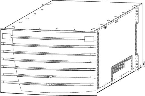
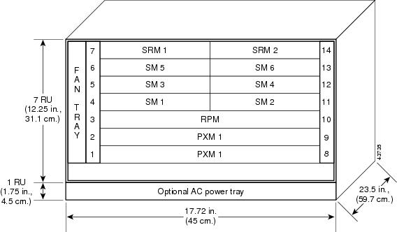
he MGX 8230 functions as a feeder to the IGX, BPX or MGX 8850 switches, or can be used for bringing in service. It has a 7-slot (double-height) chassis, and the slots are oriented in the following manner:
•
•
•
Figure 1 shows the MGX 8230 with its door attached. Note that there are light pipes in the door that display the status of the processor models (PXMs). Figure 2 is a conceptual drawing of an MGX 8230 showing the dimensions and the slot numbering. The slot numbering is as it appears from the front of the MGX 8230; slots 8 and 9 refer to back card slots only.
Note that the following features are not supported in this release, but are planned for future releases:
•
•
•
•
Figure 1 MGX 8230 with Door Attached
Figure 2 MGX 8230 Dimensions
Note
Main Features
Release 1.0 of MGX 8230 includes:
•
–
–
–
–
–
•
•
–
–
–
–
–
–
–
•
•
•
•
The MGX 8230 backplane supports a minimum of 1.2 Gbps of non-blocking switching and has a high-end limit of 21 Gbps with the PXM1. Individual line rates can range from DS0 through OC-3.
The MGX 8230 can also support a wide range of services over narrowband and mid-band user interfaces. It maps all the service traffic to and from ATM circuits based on standardized interworking methods.
The MGX 8230 supports up to 64 channelized or non-channelized T1 and E1 interfaces on a single IP + TM multiservice gateway. These interfaces support:
•
•
•
•
•
Frame-based services on T3 and E3 high-speed lines are also supported.
The MGX 8230 also supports Inverse Multiplexing for ATM (IMA) to provide ATM connectivity below T3 or E3 rates via the AUSM-8T1/E1 (AUSM/B).
The modular, software-based system architecture enables it to support new features through downloadable software upgrades or new hardware modules.
The Service Resource Module-3T3 (MGX-SRM-3T3/B), when supported in a future release, will be able to support up to 64 T1 interfaces over its three T2 lines and provide 1:N redundancy for the T1 and E1 cards. This feature is described in the MGX 8230 switch documentation, but is currently not supported by the hardware.
Standards-Based Conversion to ATM
The MGX 8230 converts all user-information into 53-byte ATM cells by using the appropriate ATM Adaptation Layer (AAL) for transport over the ATM backbone network. The individual service modules segment and reassemble (SAR) cells to eliminate system bottlenecks. The following list shows the applicable AAL for each service:
•
•
•
•
Refer to the Cisco MGX 8230 Installation and Configuration Guide for further installation and physical descriptions for the MGX 8230 switch.
MGX 8230 Cards
MGX 8230 Processor Switch Module (PXM1)
The MGX 8230 Processor Switch Module (PXM1) performs shelf control and shared-memory switching functions. It also serves as a data processing and ATM interface card. The PXM1 processor module for the MGX 8230 is identical to the PXM1 for the MGX 8250.
Primarily, the MGX 8230 PXM1 controls the switch and provides 1.2 Gbps of non-blocking, shared memory ATM switching and ATM trunking up to OC-12 speed. In addition, the PXM features:
•
•
•
The PXM1 and its two types of back cards make up the required control card set. The following are model numbers of cards supported by the MGX 8230 for this release:
The following are model numbers of cards supported by the MGX 8230 for this release:
•
•
•
•
•
•
•
•
•
PXM1 User Interface Back Card
The PXM1 User Interface card (PXM-UI) provides the MGX 8230 with the several user- interface ports. It mates with an PXM1 through the backplane and is installed in a back card slot (slot 8 or 9). As seen from the back of the MGX 8230, the PXM-UI will plug into the slot that is on the right side of its corresponding PXM1. The user-interface ports provide the following functions:
•
•
•
The PXM UI has the following physical connectors and interfaces:
•
•
•
•
•
•
MGX 8230 OC-3 Uplink Back Card
The MGX 8230 Uplink back card, which mates with a corresponding PXM1 through the backplane, provides the feeder trunk to the MGX switch. This uplink back card can provide either a multi-mode or single-mode fiber OC-3 interface:
•
•
•
FRSM Cards
The primary function of the FRSM is to convert between the Frame Relay-formatted data and ATM/AAL5 cell-formatted data. It converts the header format and translates the address for Frame Relay port/DLCIs, ATM-Frame UNI (FUNI) port/frame address, or frame forwarding port, and the ATM virtual connection identifiers (VPI/VCIs).
The MGX 8230 supports the following FRSM models:
•
The FRSM-8T1 card provides interfaces for up to eight T1 lines, each of which can support one 56 Kbps or one Nx64 Kbps FR-UNI, FR-NNI port, ATM-FUNI, or a Frame Forwarding port. Note that this unchannelized card cannot be configured to support sub-T rates.•
The FRSM-8T1-C card provides interfaces for up to eight T1 lines, each of which can support up to twenty-four 56 Kbps or Nx64 Kbps FR-UNI, FR-NNI, ATM-FUNI, or Frame Forwarding ports.•
The FRSM-8E1 card provides interfaces for up to eight E1 lines, each of which can support one 56 Kbps or one Nx64 Kbps FR-UNI, FR-NNI, ATM-FUNI, or Frame Forwarding port.•
The FRSM-8E1-C card provides interfaces for up to eight E1 channelized Frame Relay lines, each of which can support multiple (up to thirty-one) 56 Kbps or Nx64 Kbps FR-UNI, FR-NNI, ATM-FUNI, or Frame Forwarding ports.•
The FRSM-2E3/T3 card provides interfaces for up to two T3 or E3 Frame Relay lines, each of which can support either two T3 lines (each at 44.736 Mbps) or two E3 lines (each at 34.368 Mbps) FR-UNI, FR-NNI, ATM-FUNI, or Frame Forwarding ports.•
The FRSM-2CT3 card supports interfaces for up to two T3 channelized Fame Relay lines, each of which supports 56 Kbps, 64 Kbps, Nx56 Kbps, Nx64 Kbps, T1 ports for a total of 256 ports that can be freely distributed across the two T3 lines.•
The FRSM-HS2 provides unchannelized Frame Relay service for up to 1000 user-connections over two HSSI lines on the SCSI2-2HSSI back card. The maximum rate for the card is 104 Mbps. Each port can operate in either DTE or DCE mode with incremental rates of N x T1 or N x E1 up to 52 Mbps.OC-12 Uplink Back Card
For Automatic Protection Switching (APS) requires the "B" model—an SMFLR-1-622/B.
SMFIR-1-622 Back Card
For Automatic Protection Switching (APS) requires the "B" model—an SMFIR-1-622/B.
BNC-2T3 Back Card
BNC-2E3 Back Card
Two versions of the BNC-2E3 card are available. The BNC-2E3A applies to Australia only, and the BNC-2E3 applies to all other sites that require E3 lines on the PXM uplink card.
ATM Universal Service Module
AUSM/B Front Card
AUSM/B Back Cards
The MGX-AUSM/B-8T1 and MGX-AUSM/B-8E1 use the generic 8-port T1 or E1 line modules that operate with the 8-port service modules. The standard T1 version of the back card has eight RJ-48 connectors. The standard versions of the E1 back card have either eight RJ-48 connectors or eight pairs of SMB connectors. The following back cards are compatible with the AUSM/B:
•
•
•
Circuit Emulation Service Module 8T1E1
CESM Models
The MGX 8230 supports the following CESM models:
•
The CESM-8T1 card provides interfaces for up to eight T1 lines, each of which is a 1.544 Mbps structured or unstructured synchronous data stream.•
The CESM-8E1 card provides interfaces for up to eight E1 lines, each of which is a 2.048 Mbps structured or unstructured synchronous data stream.•
The CESM-8T1E1 card set consists of the CESM-8T1E1 front card and one of the following back cards:
•
•
•
Redundancy Architecture
Since the MGX 8230 chassis is a smaller form factor MGX 8850, most of the redundancy features available in MGX 8850 are available in MGX 8230 chassis. The following is a list of available redundancy features on the MGX 8230 chassis.
•
•
•
•
•
•
•
MGX 8230 Management
To give you access for control purposes, the MGX 8230 switch supports high- and low-level user interfaces. You can use the Cisco WAN Manager application (formerly StrataView Plus) for connection management, the CiscoView application for hardware configuration, and a command line interface for low-level control of hardware functionality and connection control. An assortment of ports and protocols supports these user-interfaces. For communicating with the MGX 8230 switch, the control port (SLIP protocol only), the LAN (Ethernet) port, and the in-band ATM connection (feeder application only) all support access by the command line interface (CLI) via Telnet, TFTP, and SNMP protocols.
The downloadable firmware on each card determines the functionality, and you can upgrade functionality by downloading new firmware through a TFTP application on a workstation or a PC.
The current status and configuration parameters of the MGX 8230 modules reside in a Management Information Base (MIB). The firmware on each card updates the MIB as changes in status and configuration occur.
MGX 8250
The Cisco MGX 8250 wide-area edge switch supports:
•
•
•
•
•
It does not support PNNI, despite the fact that some CLI commands may show options for PNNI.
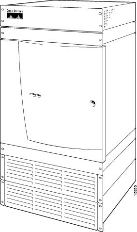
This chapter contains a brief outline of the features of the Cisco MGX 8250 switch. An illustration of the AC-powered version of the switch appears in Figure 3.
Figure 3 MGX 8250 Switch
The Applications of the MGX 8250 Switch
The MGX 8250 switch operates in two operational applications:
•
•
For a description of how to configure the switches for a particular application, see the MGX 8250 Switch Installation and Configuration Guide.
The switch is also capable of supporting Cisco Multiprotocol Label Switching (MPLS).
Universal Edge Architecture
The MGX 8250 switch can support a wide range of services over narrowband and mid-band user interfaces. It maps all the service traffic to and from ATM by using standardized interworking methods.
The supported interfaces for user-traffic are:
•
•
•
•
The optional Service Resource Module-3T3 (MGX-SRM-3T3/B) can support up to 80 T1 interfaces over its three T3 lines and provide 1:N redundancy for the T1 and E1 cards.
The modular, software-based system architecture enables the switch to support new features through downloadable software upgrades or new hardware modules.
The MGX 8250 backplane supports a minimum of 1.2 Gbps of non-blocking switching. Individual line rates range from DS0 through OC-12.
Standards-Based Conversion to ATM
The MGX 8250 switch converts all user information into 53-byte ATM cells by using the appropriate ATM Adaptation Layer (AAL) for transport over the ATM backbone network. The individual service modules segment and reassemble (SAR) cells to eliminate system bottlenecks. The following list shows the applicable AAL for each service:
•
•
•
•
MGX 8250 Cards
The MGX 8250 switch supports core cards and service modules. The Processor Switching Module (PXM) and optional Service Resource Module (SRM) are core cards. In addition to the PXM being a core card, it is also part of a a card set. A card set consists of a front card, a back card, and a daughter card. Service modules are not combined in this manner and are never part of a card set. Instead, service modules provide the interface to the transport technologies of the CPE—Frame Relay, ATM, and so on. The MGX 8250 enclosure contains up to 24 service modules (I/O cards) and 4 optional Service Redundancy Modules (SRMs) provide redundancy. A card set consists of a front card with its attached daughter card and a back card (or line module). The front card contains the processing intelligence and, on the daughter card, the firmware that distinguishes the interface (OC-3, T3, E3, and so on). The back card is a simple card that provides the electrical interface for one or more lines of a particular type. The MGX 8250 front and back cards are the:
•
This front card controls the switch and supports external interfaces for user-access and trunking or UNI ports. The back cards consist of a user interface card (PXM-UI) and a broadband network module (see subsequent list items).•
The PXM1-UI is the user interface card that has various types of ports to let you access and control the switch.•
The SMFIR-1-622 is a broadband network module for the PXM and provides a SONET OC12/STM4 ATM interface at 622 Mbps.•
The MMF-4-155 is a broadband network module for the PXM and provides 4 SONET OC3/STM1 ATM interfaces at 155 Mbps.•
The MGX-BNC-2T3 is a broadband network module for the PXM and provides 2 T3 ATM interfaces.•
The MGX-BNC-2E3 is a broadband network module for the PXM and provides 2 E3 ATM interfaces. A version for Australia, New Zealand, and elsewhere is available (MGX-BNC-2E3A).•
The MGX-FRSM-2E3/T3 provides interfaces for up to two T3 or E3 frame relay lines, each of which can support either 2 T3 lines (each at 44.736 Mbps) or 2 E3 lines (each at 34.368Mbps) FR-UNI, ATM-FUNI, or Frame Forwarding port.•
The MGX-FRSM-2CT3 supports interfaces for up to two T3 channelized frame relay lines, each of which supports 56 Kbps, 64 Kbps, Nx56 Kbps, Nx64 Kbps, T1 ports for a total of 256 ports that can be freely distributed across the two T3 lines.•
The MGX-HS2/B supports interfaces for 2 unchannelized HSSI lines, each of which supports approximately 51 Mbps. With both lines operating, maximum throughput is 70 Mbps.•
The AX-FRSM-8T1 provides interfaces for up to eight T1 lines, each of which can support one 56 Kbps or one Nx64 Kbps FR-UNI, ATM-FUNI, or a Frame Forwarding port. Note that this unchannelized card cannot be configured to support sub-T rates.•
The AX-FRSM-8T1c provides interfaces for up to eight T1 lines, each of which can support up to 24 56 Kbps or N x 64 Kbps FR-UNI, ATM-FUNI, or Frame Forwarding port.•
The AX-FRSM-8E1 provides interfaces for up to eight E1 lines, each of which can support one 56 Kbps or one N x 64 Kbps FR-UNI, ATM-FUNI, or frame forwarding port.•
The AX-FRSM-8E1c provides interfaces for up to 8 E1 channelized frame relay lines Each line can support N x 64-Kbps or (up to 31) 56-Kbps FR-UNI, ATM-FUNI, or frame forwarding ports.•
The MGX-AUSM/B-8T1 provides interfaces for up to eight T1 lines. You can group N x T1 lines to form a single, logical interface (IMA).•
The MGX-AUSM/B-8E1 provides interfaces for up to eight E1 lines. You can group N x E1 lines to form a single, logical interface (IMA).•
The AX-CESM-8T1 provides interfaces for up to eight T1 lines, each of which is a 1.544 Mbps structured or unstructured synchronous data stream.•
The AX-CESM-8E1 provides interfaces for up to eight E1 lines, each of which is a 2.048-Mbps structured or unstructured synchronous data stream.•
The RPM is a Cisco 7200-series router redesigned as a double-height card. Each RPM uses two single-height back cards. The back-card types are: single-port Fast Ethernet, four-port Ethernet, and single-port (FDDI).•
The optional MGX-SRM-3T3/B provides bit error rate testing (BERT), 1:N redundancy for T1 and E1 service modules, and a de-multiplexing function for T1 service called bulk mode.•
A multi-personality back card that supports either X.25 or V.35 interface.MGX 8250 Management
To give you access for control purposes, the MGX 8250 switch supports high- and low-level user interfaces. You can use the Cisco WAN Manager application (formerly StrataView Plus) for connection management, the CiscoView application for hardware configuration, and a command line interface for low-level control of hardware functionality and connection control. An assortment of ports and protocols supports these user-interfaces. For communicating with the MGX 8250 switch, the control port (SLIP protocol only), the LAN (Ethernet) port, and the in-band ATM connection (feeder application only) all support access by the command line interface (CLI) via Telnet, TFTP, and SNMP protocols.
The downloadable firmware on each card determines the functionality, and you can upgrade functionality by downloading new firmware through a TFTP application on a workstation or a PC.
The current status and configuration parameters of the MGX 8250 modules reside in a Management Information Base (MIB). The firmware on each card updates the MIB as changes in status and configuration occur.
Continued Support for the MGX 8850
The Cisco MGX 8850 wide-area edge switch supports:
•
•
•
•
•
It does not support PNNI, despite the fact that some CLI commands may show options for PNNI.
An illustration of the AC-powered version of the switch appears in Figure 4.
Figure 4 MGX 8850 Switch
The Applications of the MGX 8850 Switch
The MGX 8850 switch operates in two operational applications:
•
•
For a description of how to configure the switches for a particular application, see the MGX 8250 Switch Installation and Configuration Guide.
The switch is also capable of supporting Cisco Multi-Protocol Label Switching (MPLS).
Universal Edge Architecture
The MGX 8850 switch can support a wide range of services over narrowband and mid-band user interfaces. It maps all the service traffic to and from ATM by using standardized interworking methods. When the MGX 8850 switch operates as a feeder, it uses a single port to communicate the aggregated traffic over an ATM interface with an MGX 8850 or BPX 8600-series switch.
The supported interfaces for user-traffic are:
•
•
•
•
The optional Service Resource Module-3T3 (MGX-SRM-3T3/B) can support up to 80 T1 interfaces over its 3 T3 lines and provide 1:N redundancy for the T1 and E1 cards.
The modular, software-based system architecture enables the switch to support new features through downloadable software upgrades or new hardware modules.
The MGX 8850 backplane supports a minimum of 1.2 Gbps of non-blocking switching up to
45 Gbps. Individual line rates range from DS0 through OC-12.Standards-Based Conversion to ATM
The MGX 8850 switch converts all user-information into 53-byte ATM cells by using the appropriate ATM Adaptation Layer (AAL) for transport over the ATM backbone network. The individual service modules segment and reassemble (SAR) cells to eliminate system bottlenecks. The following list shows the applicable AAL for each service:
•
•
•
•
MGX 8850 Cards
The MGX 8850 switch supports two types of card sets: the core cards (or core modules) and service modules. The Processor Switching Module (PXM) and optional Service Resource Module (SRM) are core cards. The service modules provide the interface to the transport technologies of the CPE—Frame Relay, ATM, and so on. The MGX 8850 enclosure contains up to 24 service modules (I/O cards) and 4 optional Service Redundancy Modules (SRMs) provide redundancy. A card set consists of a front card with its attached daughter card and a back card (or line module). The front card contains the processing intelligence and, on the daughter card, the firmware that distinguishes the interface (OC-3, T3, E3, and so on). The back card is a simple card that provides the electrical interface for one or more lines of a particular type. The MGX 8850 front and back cards are the:
•
This front card controls the switch and supports external interfaces for user-access and trunking or UNI ports. The back cards consist of a user interface card (PXM-UI) and a broadband network module (see subsequent list items).•
The PXM1-UI is the user interface card that has various types of ports to let you access and control the switch.•
The SMFIR-1-622 is a broadband network module for the PXM and provides a SONET OC12/STM4 ATM interface at 622 Mbps.•
The MMF-4-155 is a broadband network module for the PXM and provides 4 SONET OC3/STM1 ATM interfaces at 155 Mbps.•
The MGX-BNC-2T3 is a broadband network module for the PXM and provides 2 T3 ATM interfaces.•
The MGX-BNC-2E3 is a broadband network module for the PXM and provides 2 E3 ATM interfaces. A version for Australia, New Zealand, and elsewhere is available (MGX-BNC-2E3A).•
The MGX-FRSM-2E3/T3 provides interfaces for up to two T3 or E3 frame relay lines, each of which can support either 2 T3 lines (each at 44.736 Mbps) or 2 E3 lines (each at 34.368Mbps) FR-UNI, ATM-FUNI, or Frame Forwarding port.•
The MGX-FRSM-2CT3 supports interfaces for up to two T3 channelized frame relay lines, each of which supports 56 Kbps, 64 Kbps, Nx56 Kbps, Nx64 Kbps, T1 ports for a total of 256 ports that can be freely distributed across the two T3 lines.•
The MGX-HS2/B supports interfaces for 2 unchannelized HSSI lines, each of which supports approximately 51 Mbps. With both lines operating, maximum throughput is 70 Mbps.•
The AX-FRSM-8T1 provides interfaces for up to eight T1 lines, each of which can support one 56 Kbps or one Nx64 Kbps FR-UNI, ATM-FUNI, or a Frame Forwarding port.•
The AX-FRSM-8T1c provides interfaces for up to eight T1 lines, each of which can support up to 24 56 Kbps or N x 64 Kbps FR-UNI, ATM-FUNI, or Frame Forwarding port.•
The AX-FRSM-8E1 provides interfaces for up to eight E1 lines, each of which can support one 56 Kbps or one N x 64 Kbps FR-UNI, ATM-FUNI, or frame forwarding port.•
The AX-FRSM-8E1c provides interfaces for up to 8 E1 channelized frame relay lines Each line can support N x 64-Kbps or (up to 31) 56-Kbps FR-UNI, ATM-FUNI, or frame forwarding ports.•
The MGX-AUSM/B-8T1 provides interfaces for up to eight T1 lines. You can group N x T1 lines to form a single, logical interface (IMA).•
The MGX-AUSM/B-8E1 provides interfaces for up to eight E1 lines. You can group N x E1 lines to form a single, logical interface (IMA).•
The AX-CESM-8T1 provides interfaces for up to eight T1 lines, each of which is a 1.544 Mbps structured or unstructured synchronous data stream.•
The AX-CESM-8E1 provides interfaces for up to eight E1 lines, each of which is a 2.048-Mbps structured or unstructured synchronous data stream.•
The RPM is a Cisco 7200-series router redesigned as a double-height card. Each RPM uses two single-height back cards. The back-card types are: single-port Fast Ethernet, four-port Ethernet, and single-port (FDDI).•
The optional MGX-SRM-3T3/B provides bit error rate testing (BERT), 1:N redundancy for T1 and E1 service modules, and a de-multiplexing function for T1 service called bulk mode.•
A multi-personality back card that supports either X.25 or V.35 interface.MGX 8850 Management
To give you access for control purposes, the MGX 8850 switch supports high and low-level user interfaces. You can use the Cisco WAN Manager application (formerly StrataView Plus) for connection management, the CiscoView application for hardware configuration, and a command line interface for low-level control of hardware functionality and connection control. An assortment of ports and protocols supports these user-interfaces. For communicating with the MGX 8850 switch, the control port (SLIP protocol only), the LAN (Ethernet) port, and the in-band ATM connection (feeder application only) all support access by the command line interface (CLI) via Telnet, TFTP, and SNMP protocols.
The downloadable firmware on each card determines the functionality, and you can upgrade functionality by downloading new firmware through a TFTP application on a workstation or a PC.
The current status and configuration parameters of the MGX 8850 modules reside in a Management Information Base (MIB). The firmware on each card updates the MIB as changes in status and configuration occur.
Features Introduced in Release 1.1.23
MGX 8850 Release 1.1.23 is a maintenance release of Release 1.1.22. In addition, it introduces the following new features:
•
•
•
•
•
Features Introduced in Release 1.1.22
MGX 8850 Release 1.1.22 is a maintenance release of Release 1.1.21. In addition, it introduces the following new features:
•
•
•
Features Introduced in Release 1.1.21
MGX 8850 Release 1.1.21 includes all the features in Release 1.1.12 and earlier. In addition, it introduces the following new features:
•
•
Support for the FRSM-HS1B dual-personality back-card that can be configured for either V.35 interfaces or X.21 interfaces.
•
–
–
–
•
–
–
–
•
–
–
–
This feature reduces switchover time for the above service modules.
•
–
–
–
–
•
This feature supports running the T3 or E3 lines on the FRSM at sub rates. The interfaced DSU/CSU supported are the Digital Link DL3100 for T3 and the Digital Link DL3100E for E3.
Features Introduced in Release 1.1.12
MGX 8850 Release 1.1.12 was a maintenance release of Release 1.1.11. In addition, it introduced the following new features:
•
–
–
Note
•
•
Features Introduced in Release 1.1.11
MGX 8850 Release 1.1.11 was a maintenance release of Release 1.1.10. In addition, it introduced the following new features:
•
–
–
–
–
–
–
–
–
–
Note
•
The RPM has a custom ASIC on it called the ATMizer. This chip is being replaced by the ATMizer II+, AKA "G10" version of the chip. The RPM-B contains this new chip, along with a 16Mbyte Flash SIMM instead of 4Mbyte. The RPM-B can operate at 21Mhz and 42Mhz Cellbus clock rate with 1.1.11 and 12.0.5T1, while the RPM-A can only operate at 21 Mhz.
•
•
Note
•
•
•
•
•
•
Features Introduced in Release 1.1.10
MGX 8850 Release 1.1.10 provided the following features in addition to the ones provided in Release 1.1.01 and earlier:
•
•
•
Release 1.1.25 MGX 8850 Hardware
MGX 8850 is a 45 Gbps backplane with 1.2 Gbps switching fabric for Release 1.1.25. The same backplane is used with different switching fabric cards (1.2, 45 Gbps) to achieve scalability. MGX 8850 Release 1.1.25 hardware components and their revisions that are supported are as follows:
Support for embedded Cisco IOS router (Router Processor Module - RPM)
•
–
–
–
MGX 8220 Hardware Not Supported on Release 1.1.25 of the MGX 8850
The following cards are not supported in Release 1.1.25:
•
•
•
•
•
MGX 8220 Hardware that has been superseded on the MGX 8850 by MGX 8850-specific Hardware
•
The MGX-SRM-3T3-C front card replaces the original AX-SRM-3T3-A front card and the MGX-BNC-3T3 back card replaces the original AX-BNC-3T3 back card. This change allows the use of slots 9, 10, 25, and 26 for 1:n redundancy and BERT in the MGX 8850 chassis. Both the AX-SRM-3T3-A/AX-BNC-3T3 card set and the MGX-SRM-3T3-C/MGX-BNC-3T3 card set are supported on the MGX 8220.
New card should have enabled use of bulk distribution in slots 9 and 10. 1:N redundancy should have been supported in those slots with the model A card.
•
Superseded by the MGX-SCSCI2-2HSSI/B, which works with the MGX-FRSM-HS2 front card. A V.35 interface is supported on the MGX-FRSM-HS1/B in this release.
•
Superseded by MGX-AUSM-8T1/B and MGX-AUSM-8E1/B
•
Superseded by MGX-AUSM-8T1/B and MGX-AUSM-8E1/B
MGX 8220 Hardware Not Supported on the MGX 8850
•
•
•
•
Software Platform Features
MGX 8850 provides high speed native ATM interfaces which can be configured as ATM UNI ports or trunks
Support for 1:N and 1:1 Service Module Redundancy, as indicated in the following table:
Support for Bulk Distribution using SRM-3T3-C card.
Service module and PXM upgrades.
Features Not Supported in this Release
•
•
•
•
•
•
•
•
•
•
•
•
•
•
•
Note
Major Network Management Features
•
•
•
•
•
•
•
For more details refer to the CWM Release 9.2.07 release notes part number 78-6659-07.
Connection Limits
•
•
•
•
SNMP MIB
The SNMP MGX 8850 MIB is being provided with the delivery of Release 1.1.24 of the MGX 8850 software on CCO. The MIB is in standard ASN.1 format and is located in the ASCII text files MGX8800Mib.my file which is included in the same directory within CCO. These files may be compiled with most standards-based MIB compilers. For changes in this MIB from release 1.1.23, please refer to the MIB release notes on CCO.
Notes & Cautions
CLI modification and changes in this release
dspfail <slotno>
shows all failed connections per slot basis
dspfabit <slotno>
shows all A-bit failed connections per slot basis
dsplmiloop
shows if lmi loop is present
chkslotcon <slotno>
checks database consistency per slot basis
chkportcon <slotno> <portno>
checks database consistency per slot basis
Chkcon <slot.port.vpi.vci>
checks database consistency per connection basis
dspbecnt
displays bit error count
CLI modification and changes in previous releases
•
–
–
–
–
–
–
–
–
–
–
–
–
–
Syntax:
cnfifip "Interface IPaddr [NetMask [BroadcastAddr]]"
or cnfifip "Interface Flag"
Interface -- 26/28/37 (26:Ethernet 28:SLIP 37:ATM)
or Ethernet/SLIP/ATM
IP_Addr -- <n>.<n>.<n>.<n> (<n>: integer 0..255)
Net_Mask -- <n>.<n>.<n>.<n> (<n>: integer 0..255)
BroadcastAddr -- <n>.<n>.<n>.<n>
(<n>: integer 0..255)
Flag -- a string "UP" or "DOWN"
Example:
> cnfifip atm 192.9.200.1 255.255.255.128
This configures the ATM interface and brings it UP.
> cnfifip atm up
This will bring up the ATM interface with current information in database.
> cnfifip atm down
This will bring down the ATM interface and preserve the information in the database.
–
Syntax:
delifip Interface
Interface -- 26/28/37 (26:Ethernet 28:SLIP 37:ATM) or Ethernet/SLIP/ATM
Example:
> delifip 37
This will bring down the ATM interface and delete the information in the database
–
Example:
> dspifipInterface Flag IP Address Subnetmask Broadcast Addr--------------- ---- --------------- --------------- ---------------Ethernet/lnPci0 UP 172.29.37.77 255.255.255.0 172.29.37.255SLIP/sl0 DOWN 172.29.36.253 255.255.255.252 (N/A)ATM/atm0 UP 192.9.200.1 255.255.255.128 0.0.0.0
This command shows the current condition of all 3 interfaces. The data shown for the SLIP interface will apply when it is turned UP with, say, "cnfifip slip on".
–
Syntax:
cnfenetgw IPAddr
Example:
> cnfenetgw 172.29.37.1This command will set the default gateway and add the appropriate routes necessary to it.
–
Example:
> dspenetgwEnet Gateway: 172.29.37.1–
Several lines are essential for the network to function:
- boot device : lnPci
(The only Ethernet interface)
- inet on ethernet (e) : 172.29.37.40:ffffff00
(IP address and subnetmask)
- gateway inet (g) : 172.29.37.1
(Default Ethernet gateway)
The PXM will try to correct bad entries when it boots up. This information will be copied to the standby card and if different than the shelf ip address it will up the interface on the standby with the bootChange ip address. The shellconn version of this command only updates the local bootline values and is not copied to the other card.
–
Used to bring up the Ethernet interface when CLI prompt is not there or in backup boot if it's not enabled
The following commands which are related to FRSM-2CT3 line level loopbacks.
•
This loopback can be configured in FRSM-2CT3 using the following commands.
addds3rmtloop <lineno>
xcnfln -ds3 <lineno> -e 3 -lpb 2
•
This loopback can be configured in FRSM-2CT3 using the following commands.
addds3loop <lineno>
xcnfln -ds3 <lineno> -e 3 -lpb 3
DS3 Loopback status will be displayed with following commands:
dspds3ln <lineno>
dspalm -ds3 <lineno>
dspalms -ds3
FEAC codes monitoring and Inband loopbacks for DS3 are not supported in FRSM-2CT3
•
This loopback can be configured in FRSM-2CT3 using the following commands:
cnfbert (from PXM)
addrmtloop <lineno>
xcnfln -ds1 <lineno> -e 3 -lpb 2
•
This loopback can be configured in FRSM-2CT3 using the following commands:
cnfbert (from PXM)
addlnloop <lineno>
xcnfln -ds1 <lineno> -e 3 -lpb 3
DS1 Loopback status will be displayed with following commands:
dspln <lineno>
dspalm -ds1 <lineno>
dspalms -ds1
•
xcnfln -ds1 <lineno> -e 3 -detect 2
•
•
•
–
–
–
Node Related
At most one BERT test can be performed per shelf at any point in time. BERT can only be activated through the CLI.
Do not execute the restoreallcnf command in the middle of the installation process. If you follow the following steps:
Step 1
Step 2
Step 3
Step 4
The dsplns command will display a line as disabled, but you cannot run an addln command. Do not execute the restoreallcnf command until the install and newrev commands have completed.
The correct order for the restore procedure is:
Step 1
Step 2
Step 3
Step 4
(for more information, refer to CSCdm57683)
Addln should be issued before issuing addapsln.
The following line and alarm related commands have been modified to allow slots 8, 16 and 32 as valid arguments if PXM at slot 8 is active:
•
•
•
•
•
•
•
•
•
•
•
•
•
•
•
Full SRM redundancy requires redundant SRMs. There must be SRMs in BOTH slot 15 and 16 to ensure service module redundancy for the upper shelf AND SRMs in BOTH slot 31 and 32 to ensure service module redundancy for the lower shelf. Lack of the second SRM in either shelf may result in mismatch conditions.
For service module redundancy support, if the active service module is physically removed from the slot then a switchcc would cause the now active service module to be inaccessible. The workaround is to make sure that both the active and standby cards are physically present in their slots. If the active card indeed needs to be removed then at shellconn type: pmmStartScmPolling(slotnumber) after the switchcc.
If you are moving service modules from an existing MGX 8220 platform to the MGX 8850, the MGX 8220 service modules (AX-FRSM-8T1/E1, and AX-CESM-8T1/E1) need to have the boot flash upgraded to MGX 8220 Release 5.0.00 common boot code (1.0.01 version) before they can be plugged in to the MGX 8850 chassis. All MGX-8220 service module versions that use release 4.0.xx of boot code and earlier are not supported in the MGX 8850.
If loading of the correct common boot code image is required then it will have to be performed on an MGX 8220 chassis, and cannot be performed on an MGX 8850 chassis. Please refer to the procedure below, which is also outlined in the Cisco MGX 8850 Installation and Configuration publication on the documentation CD.
Step 1
Step 2
Step 3
tftp <ip address of the MGX 8220 shelf >binput <boot filename> AXIS_SM_1_<slot#>.BOOTInsure that tftp downloaded the appropriate boot code by verifying the flash checksums.
Step 1
cc <slot #>'Step 2
chkflash'If NOT, repeat the process until they are the same. If they are the same, then you can safely remove the card. At this point the service module can be used in the MGX 8850 shelf.
Caution
Whenever an MGX 8850 is added as a feeder to a BPX 8600, SWSW automatically programs a channel with a VPI.VCI of 3.8 for use as the IP Relay channel. IP Relay is used to send IP data between nodes via the network handler; allowing every node in the domain to be directly addressable via IP addressing and CWM workstations to communicate with every node (especially feeders) using TELNET, SNMP and CWM protocols. If the user tries to add a channel with a VPI.VCI of 3.8, the BPX 8600 does not prevent the user channel from being added, but the MGX 8850 rejects it. To delete the added channel on the BPX 8600, and to get IP relay working you need to reset the BXM card.
In addition to clearing all the configuration, clrallcnf clears the network IP addresses. IP addresses and netmasks stay the same (dspifip). However, it's recommended by engineering to reconfigure them using the cnfifip command. Network IP is gone (dspnwip), and must be reconfigured using the cnfifip command. Refer to the entry on cnfifip in the Cisco MGX 8850 Command Reference publication on the documentation CD for syntax.
•
A minimum of two and up to four IP addresses are needed to be configured for MGX 8850 (one or more of the following: ethernet, ATM, SLIP) and the boot IP address. The user should use "bootChange" to set up IP gateway when the PXM card is just installed. The IP default gateway should be on the same subnet as the PXM board. Use the bootChange command to set correct IP address, netmask, and default gateway.
Do not install a Y cable on the UIA CP port for PXMs. If you do both serial ports will be enabled and you will not be able to communicate at all with the shelf through the console ports. If after switchcc standby PXM loses the downlevel port then it is due to a downlevel Beta version of UIA backcard that were shipped during field-trial only. Upgrading the UIA back card to the latest version should fix this problem.
To configure the external clock source, use the interface label 7.35. Do not use 0.33 or 7.33
There are also routeShow/routeAdd/routeDelete commands for modifying routing tables.
You must reboot your PXM after each modification with "bootChange" for it to take effect. Also make sure the subnet mask is 255.255.0.2
. bootChange- Only enter the ethernet IP address, netmask and default gateway.- Type "." to erase incorrect entries.tigers.1.7.PXM.a > bootChange'.' = clear field; '-' = go to previous field; ^D = quitboot device :lnPciprocessor number :0host name :C <-- Please put "C".file name :inet on ethernet (e) :172.29.37.40:ffff00 <-- Ethernet IP Addr/Netmaskinet on backplane (b):host inet (h) :gateway inet (g) :172.29.37.1 <-- Default Gatewayuser (u) :ftp password (pw) (blank = use rsh):flags (f) :0x0target name (tn) :startup script (s) :other (o) :- Type in reboot, after this the command "ping" will work:tigers.1.7.PXM.a > ping 171.71.54.53 1171.71.54.53 is aliveConfiguration save and restore is only supported through the CLI (CWM does not support configuration save and restore).- Service module upgrades error handling is not provided. If the user skips any of the steps during upgrade or if a power failure happens in the middle of the upgrade, results will be unpredictable. See the Special Installation and Upgrade requirements section for service module upgrades. To recover from procedural errors contact your TAC support personnel.
The MGX 8850 supports 15 simultaneous telnet sessions and 10 tftp sessions.
You must use the following Y cables for FRSM-HS2 and FRSM-CT3 redundancy as specified in the Product Orderability Matrix (Straight Cable: 72-0710-01, Crossover Cable: 72-1265-01, Straight Y-cable: FRSM-HS2: CAB-SCSI2-Y, FRSM-CT3: CAB-T3E3-Y). Other cables are not supported.
Y cable redundancy for FRSM-HS2, FRSM-2CT3, FRSM-2T3, FRSM-2E3 is only supported for adjacent slots.
Statistics are not supported for the RPM.
There is no need to issue the syncdisk and shutdisk commands before removing the PXMs. The system quiesces the disk by detecting the removal of the PXM board and flushes the write buffers to the disk and puts the PXM in sleep mode. This disables any further hard disk access since it locks the actuator. When the card is reinserted the PXM automatically comes out of sleep mode.
Syntax of addlink command has changed as follows:
New Syntax:
Syntax: addlink <T3LineNum> <T1Slot> <NumberOfT1s> <TargetSlotNum>
<TargetSlotLineNum>
<T3LineNum> where = Slot.Line
Slot = 15,31
Line = 1 - 3
<T1Slot> where T1Slot = 1 - 28
<NumberOfT1s> where NumberOfT1s = 1-8
<TargetSlotNum> where TargetSlotNum = 1-6|11-14|17-22|27-30
<TargetSlotLineNum> where TargetSlotLineNum = 1-8
PAR command cnfnwip has been disabled in this release, please use "cnfifip" instead.
If you lose power, or remove the on-line PXM you lose the broadcast address. Use the "cnfifip" command to configure the broadcast address. To re-define your ATM address and IP Address that are in the same subnet, you have to change the ATM address to a temporary address not in the same subnet, then add back your IP Address with the original Broadcast address, then go back and correct your ATM address.
Cooling and Power limitations: Customer should be aware of the need for extra power supplies and fans beyond certain limitations. A single fan tray will support all configurations that draw between 1200 and 1400 watts. For power requirements, the MGX 8850 requires a minimum of one power supply per line cord to support the power requirement for 5 cards.
This is based on an estimated worst case power requirement of 190W plus margin per card slot.
CONNECTION MANAGEMENT RELATED
The name of the node cannot be changed if there are PVCs. The node name must be changed from the default value before adding connections, since it cannot be changed later. Use the cnfname command to change the node name.
Only one feeder trunk can be configured. No BNI trunk to MGX 8850 as a feeder is supported.
The slave end of a connection must be added first.
The slave end cannot be deleted and re-added back by itself. If you delete the slave end, the entire connection must be completely torn down and re-added back. If the slave end of the connection is deleted and re-added back by itself, then unpredictable results will happen.
For user connections, VCI 3 and VCI 4 on every VPI are reserved for VPC OAMs.
The actual number of feeder connections you can provision on the PXM is always two less than you have configured. (the dsprscprtns command shows max connections as 32767, but you can only use 32767 - 2 = 32765). One connection is used for LMI and another one for IP relay.
There is no error handling detection while provisioning through the CLI. Invalid endpoints and unsupported connection types (such as connections between FRSM-CESM ports or connections between structured and unstructured connections) are permitted using the CLI. The user should not configure these connections.
The sum of CIR of all channels of a port can be greater than port speed as long as CAC is disabled. However, it is not acceptable for one channel's CIR to be greater then port speed even if CAC is disabled. Two channels added up can exceed port speed. This means you cannot oversubscribe a port if only one channel is configured.
When trying to add a port on DS0 slot 32 of a CESM-8E1 line using an SNMP set or the CiscoView Equipment Manager, The SNMP agent in CESM will time out, without adding the port. The SNMP libraries treat the 32 bit DS0 slotmap (cesPortDs0ConfigBitMap) as an integer. The value for the last DS0 is treated as the sign value. This causes a corruption in the packet coming to the agent. As the agent does not receive a complete SNMP packet, it does not respond and times out. Use the command line interface to add a port on DS0 slot 32 of a CESM-8E1 line.
The cnfport command does not allow VPI ranges to be reduced. The cnfport command only allows the VPI range to expand. The correct sequence is to delete all connections on the partitions, delete the partitions, delete the port and add the port with new VPI range.
On an FRSM-2CT3, one can add 128 ports on a group of 14 T1 lines as indicated below.
lines 1 to 14 -- 128 ports (A)
lines 15 to 28 -- 128 ports (B)
lines 29 to 42 -- 128 ports (C)
lines 43 to 56 -- 128 ports (D)
So, to add 256 ports on one T3 one should add 128 ports on the first 14 T1 lines and the remaining 128 on the next 14 T1 lines.
Note that (A) and (D) are connected to 1st FREEDM and (B) and (C) are connected to the 2nd FREEDM. Each FREEDM supports only 128 ports. If 128 ports are added on one T3 as in (A), then there cannot be any more ports as in (D). The 129th port should be on lines 15 to 42 (as in B or C).
If the user adds a connection between an RPM and a PXM and then deletes the connection the RPM shows no connection but the PXM still has the connection. The MGX was designed and implemented in such a way that only the connections that have the master end show up on PXM (by dspcons command). Consider these three connections:
c1 - has only slave end,
c2 - has only master end,
c3 - has both master and slave end.
When using the dspcons command, c2 & c3 will be displayed, NOT c1. The connection will not show up once the master end (PXM) is deleted. Recommendation: When adding a connection, if one end of the connection is PXM, always configure the PXM side to be the slave. Thus when deleting the RPM side, which is the master, the connection will not show up on the PXM. However keep in mind that the slave end (PXM) still exists. This also provides a side benefit. When a connection exists with only the slave side, no bandwidth is occupied. The bandwidth is reserved only if the master end exists (with or without the slave).
The MGX-FRSM-HS1/B is capable of supporting a total throughput (card-level) of 16 Mbps. However, it is possible to configure 4 lines each supporting up to 8 Mbps, thus oversubscribing the card. This has been raised in bug #CSCdm71476 and a restriction/warning will be added in a future release.
Addlnloop on an FRSM-HS1/B line works only when there is a (valid) cable plugged in to the backcard on that line. This is a hardware limitation on the backcard and has been mentioned in the Release-notes in bug# CSCdm44993
RPM Related
The RPM is a NPE-150 based router card capable of sustaining 150,000 pps. With RPM versions earlier than 12.O.7T1, some limitations in Inter-Process Communication between the can cause the PXM to declare that the RPM has Failed, when the RPM is at high loads. To avoid this, with RPM software releases earlier than 12.0.7T1, throughput is limited to 62,000 pps, and it is recommended that MPLS configurations are limited to 100 interfaces.
With RPM software releases from 12.0.7T1, those limitations are removed.
In a separate limitation, the number of directly-connected OSPF networks supported by an RPM is currently limited to 27. This means that any or all of the 700 subinterfaces supported by the RPM can run OSPF, but the number of distinct OSPF networks supported is limited to 27. (A work-around is available and is discussed below.) The limit of 27 arises because of the overheads of supporting separate link-state databases for separate networks. In an application where the RPM is a Provider Edge Router in an MPLS Virtual Private Network service, a much better solution in any case is to use a distance-vector routing protocol between the customer routers and the RPM. A distance-vector routing protocol provides exactly the information required for this application: reachability information, and not link-state information. The distance-vector routing protocols supported by the RPM are BGP, RIP v1 and RIP v2, as well as static routing. With RPM software releases from 12.0.7T1, distance-vector routing protocols can be used with as many different networks as subinterfaces. Currently, the RPM supports 700 subinterfaces, and hence 700 networks with BGP, RIP or static routing.
Note that if the RPM is acting as a Provider Edge Router in an MPLS Virtual Private Network service, and even if OSPF is running in a customer network, it is not necessary to run OSPF between the customer router and the RPM. If the customer edge devices run Cisco IOS, they can redistribute OSPF routing information into RIP using the IOS commands redistribute rip in the OSPF configuration, and redistribute ospf in the RIP configuration. Similar configurations are possible for BGP. Using such configurations, the RPM with IOS software release 12.0.7T1 supports 700 customer networks which use OSPF internally. (For more information on readvertisement, see the "Configuring IP Routing Protocol-Independent Features" chapter in the "Cisco IOS Release 12.0 Network Protocols Configuration Guide, Part 1".) Redistribution is not unique to Cisco CPE, and other vendors' equipment also supports redistribution.
Recommendations for Booting:
The current implementation provides the following options:
From PXM Disk
NetBoot (TFTP server)
Booting from PXM Disk is faster than NetBoot.
----------------------------------------------------------------------------------------------------------------------
Recommendations for saving RPM configuration
The current implementation provides the following options:
a. Save on flash / boot-flash.
b. Save on PXM Disk.
c. Save on network (TFTP server)
d. Save on RPM NVRAM (comes up faster; only for limited configuration size)
It is recommended to save the configuration on flash and on the PXM Disk, as well as on the network server. This ensures that the configuration can be restored; even in the case of multiple failures.
For example if an RPM card has problems, one can copy the configuration from either the PXM disk or from the network to new RPM card. In case of multiple hardware failures (both RPM and PXM cards have problems) one can copy the configuration from the network server.
----------------------------------------------------------------------------------------------------------------------
Replacing the existing RPM with a new card or a card with old configuration in flash:
The existing configuration (of the old card) can be restored on the newly inserted card by following the instructions given below:
Step 1
Step 2
Step 3
Step 4
Step 5
Please note that in RPM context the "config save/restore" feature of the PXM only restores the PXM part of the RPM configuration/connections. The RPM part of the configuration should also be saved from RPM CLI through copy command (For example: "copy run c: <config-filename>" for saving to PXM Disk) for future restoration.
----------------------------------------------------------------------------------------------------------------------
RPM Connection Resynchronization:
The RPM Connection Re-sync process is supported in the 12.04T and higher releases. This feature checks for consistency between the RPM and PXM connection databases. ----------------------------------------------------------------------------------------------------------------------
Limitations
restoreallcnf
Do not execute the restoreallcnf command in the middle of the installation process. If you do, the dsplns command will display a line as disabled, but you cannot run an addln command. Do not execute the restoreallcnf command until the install and newrev commands have completed.
The correct order for the restore procedure is:
Step 1
Step 2
Step 3
Step 4
.(for more information, refer to CSCdm57683)
The Service MIB does not support resource partitions.
LIP is supported on the maintenance port, but there is no PPP support on the maintenance port.
BIS messages are constantly being sent from BPX to various nodes. This affects the frequency of TFTP updates, which may affect CWM performance and/or CWM database consistency.
Unable to provision virtual trunks in SWSW 9.1.10.
clrsmcnf
As a speedy way to wipe out all configuration on an SM, you can use clrsmcnf. This command works in the following scenarios:
•
•
•
To be able to use an SM of a different type from the current one in a slot you can also use clrsmcnf. For example, if there is a FRSM8t1e1 in the slot with some configuration and the customer wants to use this slot for an AUSM8t1e1 card.
clrsmcnf cannot delete a port or channel due to corruption or error locally on the SM. It is able to delete the port/channel from within the PXM, but it cannot delete a port or channel due to corruption/error on the PXM itself. You can save an SM configuration and restore it back to the same slot on the same node. If the SM configuration is corrupted on disk, but the run-time image is okay and the file contented is corrupted, this is supported.
The following are NOT supported on the MGX 8850:
•
•
•
If you have more than 500 connections on a service module, before issuing clrsmcnf you need to change the session timeout default value.
Use CLI command timeout 0 (no timeout)
clrsmcnf
after it is done
Use CLI command timeout 600 (to set the timeout value back to the default)
Note
Core Dump Mask
There are no system performance implication unless you take a core dump, currently the default error mask to take core dump is attached, you can change the mask or take it manually.
Set the core dump mask to its default value. If you enable core dumps with power on reset and shell reset core dumps enabled you will end up with a PXM that continuously dumps the core and resets. The only way out is to use a download boot that does not have the core dump feature.
Default setting 0x262eeOFF 0001 Power ON ResetON 0002 DRAM Parity ErrorON 0004 WatchDog Timeout ResetON 0008 Resource OverflowOFF 0010 Clear All ConfigurationON 0020 Missing TaskON 0040 Reset because of PXM Low VoltageON 0080 Reset By Event Log TaskOFF 0100 Reset from ShellON 0200 UnknownOFF 0400 Reset from PXMOFF 0800 Reset SystemOFF 1000 Switch Core CardON 2000 Secondary Cache ErrorON 4000 Software Error ResetOFF 8000 S/W reset due to upgradeOFF 10000 Restore All ConfigurationON 20000 Device Driver ErrorNODENAME.1.8.PXM.a > core hot-dumpDo you want to proceed (Yes/No)? yDumping PXM Core Image[0]:......................................................................................... .......................................Done.NODENAME.1.7.PXM.s > core save 2 core.zipCreating core.zip.................................Core dump basics.There are two steps to save a core dump.1. The system will store a raw core dump image on the disk (this image ison a portion of the disk that is not used for the filesystem).2. After the raw core dump image is saved on the disk, use the cli command"core" to zip the image and save it in a file on the disk.Use the "core mask" command to display and to set the mask which determineswhich conditions will cause an autmatic core dump.NODENAME.1.7.PXM.s > core maskAutomatic Core Dumping is enabled..The Current Core slot is 0The Current Core mask is 0x4004OFF 0001 Power ON ResetOFF 0002 DRAM Parity ErrorON 0004 WatchDog Timeout ResetOFF 0008 Resource OverflowOFF 0010 Clear All ConfigurationOFF 0020 Missing TaskOFF 0040 Reset because of PXM Low VoltageOFF 0080 Reset By Event Log TaskOFF 0100 Reset from ShellOFF 0200 UnknownOFF 0400 Reset from PXMOFF 0800 Reset SystemOFF 1000 Switch Core CardOFF 2000 Secondary Cache ErrorON 4000 Software Error ResetOFF 8000 S/W reset due to upgradeOFF 10000 Restore All ConfigurationOFF 20000 Device Driver ErrorNODENAME.1.7.PXM.s > core mask 0x2e2eeAutomatic Core Dumping is enabled..The Current Core slot is 0The Current Core mask is 0x2e2eeOFF 0001 Power ON ResetON 0002 DRAM Parity ErrorON 0004 WatchDog Timeout ResetON 0008 Resource OverflowOFF 0010 Clear All ConfigurationON 0020 Missing TaskON 0040 Reset because of PXM Low VoltageON 0080 Reset By Event Log TaskOFF 0100 Reset from ShellON 0200 UnknownOFF 0400 Reset from PXMOFF 0800 Reset SystemOFF 1000 Switch Core CardON 2000 Secondary Cache ErrorON 4000 Software Error ResetON 8000 S/W reset due to upgradeOFF 10000 Restore All ConfigurationON 20000 Device Driver ErrorNODENAME.1.7.PXM.s >Use the "core mask default" command to set the mask back to the default.NODENAME.1.7.PXM.s > core mask defaultAutomatic Core Dumping is enabled..The Current Core slot is 0The Current Core mask is 0x262eeOFF 0001 Power ON ResetON 0002 DRAM Parity ErrorON 0004 WatchDog Timeout ResetON 0008 Resource OverflowOFF 0010 Clear All ConfigurationON 0020 Missing TaskON 0040 Reset because of PXM Low VoltageON 0080 Reset By Event Log TaskOFF 0100 Reset from ShellON 0200 UnknownOFF 0400 Reset from PXMOFF 0800 Reset SystemOFF 1000 Switch Core CardON 2000 Secondary Cache ErrorON 4000 Software Error ResetOFF 8000 S/W reset due to upgradeOFF 10000 Restore All ConfigurationON 20000 Device Driver ErrorNODENAME.1.7.PXM.s >Use the "core enable" command to enable autmatic core dumps.NODENAME.1.7.PXM.s > core enableAutomatic Core Dumping is enabled..NODENAME.1.7.PXM.s >Use the "core disable" command to disable automatic core dumps.NODENAME.1.7.PXM.s > core disableAutomatic Core Dumping is disabled..NODENAME.1.7.PXM.s >Use the "core hot-dump" to dump the raw image to the disk.NODENAME.1.7.PXM.s > core hot-dumpDo you want to proceed (Yes/No)? yDumping PXM Core Image[0]:......................................................................................... .......................................Done.NODENAME.1.7.PXM.s >Use the "core" command to list the current list of raw core dumps save onthe disk.NODENAME.1.7.PXM.s > coreSaved Core Images:Slot Reset Reason Dump Time-------------------------------------------------------------0 Unknown WED DEC 29 09:38:30 19991 WatchDog Timeout Reset FRI DEC 10 08:51:52 19992 WatchDog Timeout Reset TUE DEC 14 08:01:39 19993 WatchDog Timeout Reset TUE DEC 14 12:38:01 19994 Reset from Shell TUE DEC 14 14:45:30 19995 WatchDog Timeout Reset WED DEC 22 08:20:26 1999Automatic Core Dumping is enabled.The Current Core slot is 0NODENAME.1.7.PXM.s >Use the "core save" command to save the specified raw image to thespecified zip file.NODENAME.1.7.PXM.s > core save 0 cccCreating ccc.................................NODENAME.1.7.PXM.s >To upload the zip file, you must use FTP (TFTP has a limit of 16 MBytesfor file size).Enter shellconn:NODENAME.1.7.PXM.s > shellConn->Set the and enable the user name:-> setLoginsetLoginUser Name=========ciscovalue = 0 = 0x0->The user name is "cisco" and the password is "ciscoinc".Now you can FTP the image. Be sure to use binary mode.After the image has been uploaded, disable the user name:-> clrLoginclrLoginUser Name=========value = 0 = 0x0->
Problems Fixed in Release 1.1.25
Problems Fixed in Release 1.1.24
Problems Fixed in Release 1.1.23
Problems Fixed in Release 1.1.22
Problems Fixed in Release 1.1.21
Problems Fixed in Release 1.1.20
Problems Fixed in Release 1.1.01
One of the slots on the node had a CESM-8E1 card with some connections. The connections, ports and lines on the CESM were deleted and it was replaced with an AUSM-8T1 card.The AUSM card went to mismatch state. On trying to execute the clrsmcnf command the following error message was seen: flyers4.1.7.PXM.a > clrsmcnf 20, Do you want to proceed (Yes/No)? Yes Command Failed: Resources exist on card (CSCdm29289).
Happens on an MGX 8850 switch with two PXMs (Core Redundancy). If the Active PXM while synchronizing the databases to Standby, resets, then the Standby PXM goes to Fail State. The reset PXM comes up as Active and will show the other PXM slot as Empty (CSCdm30193)
ShelfIntegrated alarm becoming Major or Minor either after switchcc or resetsys. (CSCdm33756)
One connection, CESM-PXM UNI ended up deleted in CESM, but SPM still has some incomplete data structure. Since there is only one connection per port for the CESM, and the connection is in such state that can not be removed or re-added, the port and its bandwidth become unusable (CSCdm33289)
Configuring the DS3 framing format on an FRSM-2CT3 to M13 does not permit the card to operate correctly with other devices using that framing format. (CSCdm35575
When modifying a particular protected memory address on CESM8p which causes CESM HW watchdog reset, PXM got reset or lost SAR functionality. (CSCdm15367)
Adding or modifying a connection to an RPM fails if the RPM enable password differs from the password that Conn MGR has cached. Example: A connection to an RPM is configured, then the enable password is changed on the RPM -- any subsequent connection adds or changes fail because of a bad enable password. (CSCdm34114)
When modifying the bandwidth allocation (usually from a smaller percentage to a much bigger one) of a port with cnfport command, it is not always possible to create more connections under that port. (CSCdm32894)
The standby PXM console is not enabled for use. Downlevel PXM board (CSCdm34030)
Adding connections through a conn proxy script. Card went to failed state after adding around 700 connections. (CSCdm32773)
SMs are shown in failed state though physically they are active. This was observed for FRSM8p and FRSM-VHS in slot 5 and 6 and 1. (CSCdm21684)
While using a script to do stress switchcc test, there is a one time occurrence where it was found that the original active card did not come back as standby, but went to fail state. (CSCdm35298)
The problem is related to the PVC's traffic parameters. We are still investigating what the PCR, average, and burst values should be set to for VBR connection. This values are related to nature of the traffic which is sent to the RPM. (CSCdm35352)
When the connection is deleted, the trap does not go to SV+. (CSCdm27489)
Major differences when add vbr.2 connections on PXM by CLI and CWM (CSCdm28075)
If cnfcon command is given with the CIR value of less than 8 and greater than zero then the command is never completed and later on one cannot do any modifications, display, etc. (CSCdm34047)
Restoreallcnf does not restore the saved config. Occurs when restoring a configuration taken from another physical shelf. The card the restoreallcnf was done on will not become active but the other card will which contains the previous configuration. (CSCdm37114)
AUSM Connection addition fails for VP connection from CWM. (CSCdm36674)
At low frequencies, the jitter characteristics does not fully comply with the standards. (CSCdm38833)
Problems Fixed in Release 1.1.00
Stand-alone Statistics collection does not work if the PXM is in slot 8 (CSCdm20017).
There is no need to issue the syncdisk and shutdisk commands before removing the PXMs. The system quiesces the disk by detecting the removal of the PXM board and flushes the write buffers to the disk and puts the PXM in sleep mode. This disables any further hard disk access since it locks the acctuator. When the card is reinserted the PXM automatically comes out of sleep mode.
In Release 1.0.00 Configuration Save and Restore works only for the same firmware image even if there are no database changes from one version to the other version. In Release 1.1.00 Configuration Save and Restore can be done on different firmware images if the firmware images have compatible databases.
VPI range was limited to 0 to 255 on PXM UNI and NNI on the feeder ports in Release 1.0.00. There is no VPI range limit in Release 1.1.00. (CSCdk63920)
A flood of SNMP requests can cause SNMP and CLI to be unavailable for some time (CSCdm13663).
After a user adds PXM UNI channel, VCC with VCI=0, user cannot add any more VCCs with same (CSCdm14123)
Was unable to delete a VP connection for PXM UNI channels using CWM (CSCdm15120)
While executing "cc" command to a Service Module (SM) on a telnet session, the telnet session hangs, and the console of the active PXM card has Tlb load exception message. (CSCdm15150
Telnet session gets cut off without any error messages or obvious network problem (CSCdm15166)
When adding connections using scripts utilizing Conn-Proxy, without delay between two connection additions, and when there are line alarms at either endpoint, there is a probability that the CESM card may reboot. (CSCdk12363)
FRSM-2CT3 is dropping frames due to frame aborts detected by HDLC controller. (CSCdm13123)
Traffic on connection on FRSM-8T1E1 stopped after removal and insertion (CSCdm18521)
Cannot have more than one session on FRSM-VHS (CSCdk77924)
A channel is shown in alarm even though there is no line alarm and port alarm locally on the FRSM8p service module, and there is no remote alarm on the far end of the connection. (CSCdm14383)
Port statuses at service module site might be different with those at PXM and VSI controller site.(CSCdm15183)
A port was seen that had no alarm on FRSM8p, but dspparifs on PXM CLI shows the interface of this port in fail state. (CSCdm15620)
Attempt to configure the external clock source using the label 0.33 does not work. (CSCdm15669)
Some FRSM-8T1E1s don't come up when the MGX8850 is power cycled. (CSCdm16401)
Using script to add ports on FRSM8P Service Module card, in case a port addition fails, FRSM8 is not backing off properly and leave the port still added locally on the card even though the port is not added on PXM side and PAR (the interface corresponding to this port will not show up in dspparifs CLI on PXM, but dspports on SM shows the port added). (CSCdm03268)
Connections in alarm while lines are OK. (CSCdm10735)
Service module & the PXM reserve different bandwidth for the same connection.(CSCdk92115)
The card, after power recycle does not come up. It gets stuck in standby. (CSCdm10416)
When removing a service module or removing a line, VSI controller prints out "swerr 20208" sometimes. (CSCdm16902)
When an MGX 8850 shelf with CESM-8T1E1s is left running for over a day with Configuration Uploads going continuously, there is a possibility of allocated large buffers not getting released. (CSCdm17868)
The interface state (port state) is inconsistent between the VSI controller and the platform as well as that at service module. (CSCdm16033)
A tftp download of backboot displays an S-objlib_OBJ_UNAVAILABLE error (CSCdm16295)
While RPM is reloading after a card reset or as a result of card removal, PXM gets reset intermittently. (CSCdm15040)
CLI commands on a PXM hang after aborting a command using Ctrl-C. (CSCdm16726)
PXM reset when OC12 trunk back card was inserted. (CSCdm20010)
Broad band connection statistics fail when the PXM is in slot 8 and statistics are enabled (CSCdm20017)
Problems Fixed for RPM in 12.0.5T1
These anomalies are fixed in IOS 12.0.5T1. For generic IOS issues, refer to the 12.0.5T1 release notes.
•
•
•
•
•
•
•
•
•
Problems Fixed for RPM in 12.0.4T
These anomalies are fixed in IOS 12.0.4T. For generic IOS issues, refer to the 12.0.4T release notes.
•
•
•
•
•
•
•
•
•
•
Compatibility Notes
1.
2.
1.
Note
Compatibility Matrix
This multiservice gateway comparison matrix is designed to identify capabilities supported in the MGX 8220, 8230, 8250 and 8850 platforms.
Special Installation and Upgrade Requirements
Existing customers should use the upgrade procedure on page 92 to upgrade from 1.1.12/1.1.21/1.1.22/1.1.23/1.1.24 to 1.1.25. For new customers the image will be pre-installed as 1.1.24 and they need to use the PXM installation procedure to upgrade to future maintenance releases.
No graceful downgrade is supported from 1.1.25 or any higher version to any down level version of software below 1.1.22 because of MIB changes. This also implies that if you have to abort after newrev command (and the commit command), you have to do an ungraceful downgrade.
An upgrade from 1.1.25 to 1.1.30 for 8230 nodes is (not generally available as of October 2, 2000) not available due to a software problem. The solution to this software problem will be available in a 1.1.3x Release.
Note
Below is the procedure for ungraceful downgrade:
Step 1
abort
reload old firmware code (boot code can stay at 1.1.23)
restoreallcnf
Step 2
abort
reload the old code
goto shellConn
setPXMPrimary on both boards
issue clrallcnf on the active
Single PXM Installation Procedure
Step 1
SaveallcnfStep 2
node-prompt> ll "C:/CNF"size date time name-------- ------ ------ --------512 APR-08-1999 08:16:18 . <DIR>512 APR-08-1999 08:16:18 .. <DIR>512 APR-09-1999 05:26:42 TMP <DIR>45433 APR-09-1999 05:28:42 NODENAME_0409990528.zip45433 APR-09-1999 05:28:42 NODENAME.zipIn the file system :total space : 819200 K bytesfree space : 787787 K bytesStep 3
unix-prompt> tftp shelf.ip.addresstftp> bintftp> get CNF/NODENAME_0409990528.zipReceived 45433 bytes in 0.4 secondsStep 4
tftp <node_name or IP address>binput 1.1.23.fw POPEYE@PXM.FWquitStep 5
tftp <node_name or IP address>binput ComMat.datquitStep 6
copy ComMat.dat /FW/ComMat.datStep 7
Step 8
Installation Procedure For Redundant PXMs:
This section applies to upgrades from 1.1.10 to 1.1.11 or 1.1.12 or 1.1.21 or 1.1.22 or 1.1.23.
Caution
During graceful upgrade procedure, if after the newrev command, the non-active card enters the "MISMATCH" state, do the normal commit command. You will get a warning message:
other card not found,
do you still want to complete the commit operation
Answer yes and then reset the non-active card.
If you get the MISMATCH during the upgrade process, after you finish, you will also get the MISMATCH. To correct the mismatch, you must check your backcards, they must be identical.
Note
To set the PXM address, use the bootChange command:
node-prompt> bootChange'.' = clear field; '-' = go to previous field; ^D = quitboot device : lnPciprocessor number : 0host name :file name :inet on ethernet (e) : 172.29.37.220:ffff00inet on backplane (b):host inet (h) :gateway inet (g) : 172.29.37.1user (u) :ftp password (pw) (blank = use rsh):flags (f) : 0x0target name (tn) :startup script (s) :other (o) :Set the "inet on ethernet (e) :" field with the first part of the entry (before the :) as the IP address, and the second part as the subnet mask.
Set the "gateway inet (g) :" with the gateway address.
This must be done on both PXMs. This can also be done in backup boot from the VxWorks prompt "->".
To set the shelf IP address:
node-prompt> cnfifip 26 shelf.ip.address subnet.mask broadcast.addressThe second argument is the shelf IP address.
The third argument is the subnet mask.
The fourth argument is the broadcast address.
Step 1
saveallcnfStep 2
node-prompt> ll "C:/CNF"size date time name-------- ------ ------ --------512 APR-08-1999 08:16:18 . <DIR>512 APR-08-1999 08:16:18 .. <DIR>512 APR-09-1999 05:26:42 TMP <DIR>45433 APR-09-1999 05:28:42 NODENAME_0409990528.zip45433 APR-09-1999 05:28:42 NODENAME.zipIn the file system :total space : 819200 K bytesfree space : 787787 K bytesStep 3
unix-prompt> tftp shelf.ip.addresstftp> bintftp> get CNF/NODENAME_0409990528.zipReceived 45433 bytes in 0.4 secondsStep 4
Step 5
unix-prompt> tftp pxm.ip.addresstftp> bintftp> put pxm_1.1.23.fw POPEYE@PXM.FWSent 1982672 bytes in 18.3 secondsMake sure that the transfer is successful, by looking at the message displayed on the PXM console after the transfer:
Program length = 1982672Calculated checksum = 0xd9779bc6 stored checksum = 0xd9779bc6Fw checksum passedStep 6
tftp <node_name or IP address>bincd fwput ComMat.datcopy ComMat.dat to FW directory on the PXM.quitStep 7
Step 8
copy ComMat.dat /FW/ComMat.dateEnsure that the ComMat.dat is copied to both PXMs.
Step 9
The Standby card will reset at this point, and go to hold state.
Step 10
The Active card will be reset and go to hold state.
After the newrev the firmware should now show the new revision on dspcd.
Step 11
PXM Flash Download Procedure
Step 1
unix-prompt> tftp shelf.ip.addresstftp> bintftp> put pxm_bkup_1.1.22fw POPEYE@PXM.BTSent 642232 bytes in 6.3 secondsThe byte count above is just an example. It will be different for different images. Make sure that the boot is successfully downloaded. You should see a message like the following on the console:
Program length = 642230Calculated checksum = 0x2a5a41f2 stored checksum = 0x2a5a41f2Fw checksum passedStep 2
Service Module Firmware Download Procedure
Step 1
tftp <node_name or IP address>binput <backup boot> POPEYE@SM_1_<slot#>.BOOTquittftp <node_name or IP address>put <FW file> POPEYE@SM_1_0.FWquitYou cannot do two puts in the same tftp session.
Step 2
Step 3
Note
Service Module Installation/Upgrade and Flashdownload Requirements.
Caution
If you are moving service modules from an existing MGX 8220 platform to the MGX 8850, the MGX 8220 service modules (AX-FRSM-8T1/E1, and AX-CESM-8T1/E1) need to have the boot flash upgraded to MGX 8220 Release 5.0.00 common boot code (1.0.01 version) before they can be plugged in the MGX 8850 chassis. All MGX-8220 service module versions that use Release 4.0.xx of boot code and earlier are not supported in the MGX 8850.
SPARE DEPOT - Customers receiving a replacement service module via the TAC (through the RMA process) will have the common boot code image that works for MGX 8220 Release 4.x, 5,x and MGX 8850 installed on legacy service modules. (Spare service modules received directly from manufacturing through the normal ordering process will have the correct boot code image already loaded.)
If loading of the correct common boot code image is required then it will have to be performed on an MGX 8220 chassis, and cannot be performed on an MGX 8850 chassis. Please refer to the procedure below, which is also outlined in the Cisco MGX 8850 Installation and Configuration Guide on the documentation CD.
Use ftp to port the Axis 5 common boot image for the service module to a workstation
Plug in the card into the MGX 8220 shelf
Download the proper MGX 8220 shelf Release 5.0 boot image using the following commands from the workstation:
tftp <ip address of the MGX 8220 shelf >binput <boot filename> AXIS_SM_1_<slot#>.BOOTNow you must insure that tftp downloaded the appropriate boot code by verifying the flash checksums.
Login to the shelf.
cc <slot #>'chkflash'Verify that the two checksums are the same.
If NOT, repeat the process until they are the same. If they are the same, then you can safely remove the card. At this point the service module can be used in the MGX 8850 shelf.
Service Module Upgrades
The following steps need to be followed for service module upgrade. Service module firmware images cannot be downloaded as specific versions in MGX 8850 Release 1.1.24 because only one image can be present on the disk at one instance. Hence the user cannot revert back during the installation process.
Step 1
unix-prompt> tftp shelf.ip.addresstftp> bintptp>put frsm_8t1e1_10.0.01.fw POPEYE@SM_1_0.FWSent 1982672 bytes in 18.3 secondsMake sure that the transfer is successful, by looking at the message displayed on the PXM console after the transfer:
Program length = 1982672Calculated checksum = 0xd9779bc6 stored checksum = 0xd9779bc6Fw checksum passedRepeat for each service module type and for each slot independent firmware.
For a slot-specific image (in this example the service module is tied to slot 1),
tftp <ip address of the MGX 8850 shelf >binput frsm_<version>.fw POPEYE@SM_1_1.fwfor a slot-dependent image,
Note
•
•
Step 2
Step 3
install sm <slot> <version>where <slot> is the service module that is being upgraded
and <version> is the service module image on the disk.
Note
newrev sm <slot> <version>where <slot> is the service module that is being upgraded
and <version> is the service module image on the disk.
commit sm <slot> <version>where <slot> is the service module that is being upgraded
and <version> is the service module image on the disk.
Note
Known Anomalies for Platform Software and Service Module Firmware
The following is the list of known anomalies in the MGX 8850, Release 1.1.25 delivery. Included with each is a brief discussion of the problem. A more in depth discussion is available in the release note enclosure of the problem record in Bug Navigator
CSCdk54268
Symptom:
When sending cells with VPI=0, VCI=0 and CLP=1 on a UNI port, dspportcnt reports the cells as being discarded due to VpiVciErr and the cellrate also gets updated. However, CLP=0 cells are discarded gracefully and no port stats reported.
Conditions:
The local port is an ATM port. The other end is configured as IMA port.
Workaround:
Configure the other end of the port as an ATM port.
CSCdk71643
Symptom/Condition:
This is suppose to be an added feature that gives robust end to end connectivity with full recovery in cases of error. But unfortunately, with the current design it will take some extra effort and time to provide this. It will be part of future enhancement and may be available in the next release. Just a little note about why, any Traps sent to PAR are directed by LCN number which is not available without a complete end to end connection, which currently limits the generation of Traps for incomplete connections (after a stipulated timeout period).
For now, due to absence of these traps a little more responsibility goes to the end user who is creating end to end connections. It is important that if and when a connection is added or removed both Master and Slave end of the connection should be added or removed respectively. Only one side of a connection should not be removed to create a new connection with the other side. Hence creating and deleting connections under any circumstance is complete only with the creation and deletion of both end of the connections. Failure to do this can result in unneeded dangling connections.
CSCdk82484
Symptom:
The RPM incorrectly identifies the physical slot position when it is placed in an 8230 or other SweetPea node. This causes communication with the PXM to fail.
Conditions:
PXM and/or RPM software is running on an 8230 or other SweetPea node.
Workaround:
PXM and RPM software should be upgraded to versions that support the 8230 slot numbering scheme. The minimum level of software should be 1.1.30 on the PXM and Cisco IOS Release 121-4.1(T).
CSCdk86638
Symptom:
When using CWM to add connections, if the connection addition request times out, subsequent addition of the same connection may fail as well, complaining that the connection already exists (even though it timed out).
Description:
This is caused by two factors:
1. CWM assumes that when time out, connections are not added on the switch on which the timeout occurs, and thereby only removes other segments of the timed out connection on other involved nodes.
2. On MGX switch, when CWM reports connection timeout, it does not necessarily mean a timeout on the switch. The CWM timeout may be caused, for example, by the network delay etc. from switch and CWM. The connection may actually be provisioned on the switch.
Workaround:
Don't use the same vpi/vci/dlci used by the timed out connections. This can be fixed by CWM to perform a retrieval to check if the connection is actually provisioned or not on the switch, after connection addition times out.
CSCdk94100
Symptom:
When ILMI signaling and polling is enabled at one port and not enabled at the other end, the port on which signaling was configured does not go into the failed state.
Condition:
When address registration is also configured along with the ILMI signaling and polling at one end and the other end is not configured for any signaling.
Workaround:
Do not configure address registration along with ILMI signaling and polling only at one end.
CSCdm05358
Symptom:
When modifying a particular protected memory address on CESM8p which causes CESM HW watchdog reset, PXM got reset or lost SAR functionality.
Description:
When this happens, CESM sent a huge amount of traffic onto the management connection which is supposed to be used for intercard communication activities such as polling.
This traffic causes the SAR to spend all its resources on doing the cleaning/flushing in ISR (interrupt service).
This address should never be modified using the shellConn 'modify' command. It was used unknowingly in debug/test process.
Workaround:
Don't try to modify this protected address in shellConn (m 0xb300060) (0xb300060 is ATMizer CPU address for SAR on CESM8P).
As a general guideline, shellConn commands like 'modify memory' should not be used by the customer.
CSCdm06097
Symptom:
When the service module is in a mismatch state, and switchcc occurs, the log file gets filled.
Condition:
When switchcc occurs and the service module goes into mismatch state, SM logs the same message more than once to the PXM. An example of this message follows.Message which gets logged is like this:
02/01/1999-14:28:42 12 cmm FRSM-6-4167ASC sent slot number to SM : Old S.N.= 12 New S.N.=1202/01/1999-14:28:41 11 cmm FRSM-6-4167ASC sent slot number to SM : Old S.N.= 11 New S.N.=1102/01/1999-14:28:41 12 cmm FRSM-6-4167ASC sent slot number to SM : Old S.N.= 12 New S.N.=12Workaround:
This log file is not going to affect the functionality or performance of the card or any. This log message simply can be ignored, as it only is useful for debug purposes.
CSCdm10722
Symptom/Condition:
The install, newrev and commit commands for service module upgrade (there is no concept of downgrade here, as there exits only one valid, service module image on the disk at a time), do not follow, the same state machine as PXM commands in the current release.
Hence, it is mandatory, that for service modules, these commands are given in the documented order, which is:
(1) install
(2) newrev
(3) commit
WARNING: If these, commands are not given in the above specified order, we can be in a situation where we can have two different images running on the primary/secondary combination. However, on the disk, there is only one valid image for the service modules.
Workaround:
Assuming, that these commands were given out of order, and now we have two different images, running, on primary / secondary combination.
f1 - Old image version
f2 - Newly downloaded image
(1) Reset the secondary card, so that it comes up, with f2.
(2) Do a softswitch between the two cards, so that secondary takes over and becomes active. At the same time, primary is reset, and comes up with f2.
(3) If you may, you can now, do a softswitch, to revert back to the original primary, to restore normal state.
CSCdm11410
Symptom:
When listing a directory, some filenames contain either illegal characters or a timestamp for the name instead of a standard dos file name. These file entries will fail to be removed when passed to the remove command.
Conditions:
No specific known conditions are responsible for this problem.
Workaround:
Tools are available to clean condition up on the disk. Contact Cisco engineering.
CSCdm20583
Symptom:
When the dspcd command gets executed on the active PXM, with a standby SRM card number or vice versa, the error message is confusing:
Invalid value of slot number.
This actually indicates that the slot is not accessible. See further problem description below.
Condition:
When the dspcd command is executed with the other SRM slot numbers.
Workaround:
No Workaround is available. This is just an unclear error message problem. No logical errors.
Further Problem Description:
When the dspcd command gets executed on the active PXM and when the argument for the command is the standby SRMs slot number, the above error message is displayed. That is because from slot 7 PXM only slot 15 and 31 SRMs are accessible. Similarly for slot 8 PXM, only 16 and 32 are accessible.
CSCdm22510
Symptom:
Connection traps are not sent out when receiving A bit update from CPE.
Conditions:
The end result of this is that CWM will not be notified about the channel status change (failure or normal), neither will PXM/PAR.
The remote end is notified via in band OAM.
This applies to all service modules.
Workaround:
No Workaround
For more information on this bug, refer to CSCdm22510.
CSCdm31437
Conditions:
SV+ needs a trap when a line is added or deleted.
Symptoms:
In a Feeder case, SV+ is informed of a line addition through Inband communication. However, in case of stand-alone configuration SV+ needs a trap to determine addition or deletion of lines.
Workaround:
There is currently no Workaround for this.
CSCdm31793
Symptom:
When you configure a BERT on any line, all the channels on the local as well as the remote MGX88xx are going into alarm. However, connections on the PXM on both ends do not indicate any alarm.
Conditions:
Configure BERT on any line which is having some connections.
Workaround:
None.
CSCdm33351
Symptom/Condition: For VISM.
When an endpoint is added to a line that is already in an alarm condition, an Endpoint Added Trap message and an Endpoint is Active message are sent to the manager from VISM. However, the Endpoint Failed Indication Trap message is not sent.
Workaround:
None.
CSCdm33605
Symptom/Condition: For VISM.
When a switchover to a redundant VISM card takes place due to a reset/failure of the active VISM card, the display on CWM is not correct.
Workaround:
None
CSCdm33638
Symptom/Condition: For VISM.
When a switchover to a redundant VISM card takes place due to a reset/failure of the active VISM card, the switchover takes place but the display of active lines is not consistent between the shelf and CiscoView.
Workaround:
None.
CSCdm41079
Symptom:
When you configure CESM T1 D4/AMI line code and framing, the line will not come up. The card is not generating a T1 signal.
Conditions
When configuring CESM T1 D4/AMI line.
Workaround:
None other than use ESF/B8ZS.
CSCdm42849
Symptom:
An execution of the dlmi command to display LMI messages results in a system reboot.
Conditions:
Enable lmitrace using lmitrace command in order to start capturing LMI messages. dlmi results in system reboot.
Workaround:
dlmi is a debug command which should not be used when large number of connection are present in the system. This problem is only seen with large number of connections.
CSCdm43053
Symptom:
Connection addition fails.
Conditions:
200 connections are already provisioned in the FRSM-HS1.
Workaround:
None.
Further Problem Description:
FRSM-HS1 card only supports a maximum of 200 connections on Popeye1. Memory limitations in HS1 SRAM and DRAM place an upper limit on the number of Popeye connection data structures which can be stored in memory.
CSCdm48639
Symptom:
Better error checking needs to be provided for SM boot and firmware download. It's possible to download the boot image as firmware and vice versa.
Workaround:
The boot images must be downloaded with the .BOOT extension and the firmware with the .FW extension.
CSCdm53758
Symptom:
Channel alarms do not get propagated to the middle segment if NNI signaling is enabled.
Conditions:
This happens when the channel level traps are disabled. This will be fixed once a bulk trap mechanism is implemented to indicate channel alarms.
Workaround:
None.
CSCdm55480
Symptom:
While "downloadflash" is executing on the PXM or while the TFTP of the flash image to the service module is in progress, in circumstances when the PXM or the respective service module is reset, it leaves the flash in an unknown state. The card that was reset will not bootup the next time.
Conditions:
The problem will happen when the PXM or the respective SM is reset using the resetcd or switchcc commands while the flash is being written
Workaround:
None. Make sure that the flash is intact before executing the resetcd or switchcc commands, or any other command which will result in the reset of the card.
Further Problem Description:
If the card is reset when the flash is being written, it leaves the flash in the corrupted state. Therefore, the card does not boot up. All the soft reset commands, such as switchcc, resetcd, or addred, do not check if any flash write is going on before resetting the card.
CSCdm56094
Symptom
The far end device can not be put into a loopback using the "Far End Inband Loopback" or the "Far End ESF Loopback" options under the "DEVICE TO LOOP" menu in the "cnfbert" command. If these options are chosen as part of a BERT pattern test, then the test will not be configured as it will fail to sync the pattern.
Condition
The inband and ESF loopbacks are activated/de-activated by transmitting the loopback codes for the minimum number of seconds specified by the ANSI T1.403 specification. However, due to variations in the way time is measured by the AUSM and the far-end devices, some devices do not detect the code for the desired number of seconds and hence they do not activate/deactivate the loopback.
Workaround
This problem may not be seen on all (far-end) devices. If it is seen, then there is no workaround other than trying to repeat the test configuration till it is successful.
CSCdm69318
Symptom:
FRSM-2CT3 is stuck in boot state.
Conditions:
If a switchcc is issued at the same time that an FRSM-2CT3 is going through a reboot, the FRSM gets stuck in boot state.
Workaround:
Do switchcc only after FRSM-CT3 is comes up
CSCdm84982
Symptom:
The CLI command tstdelay displays time in microseconds instead of milliseconds.
Condition:
CLI shows the delay in microseconds, while the GUI shows the delay in milliseconds. However, the values are almost same.
Workaround:
Convert the displayed time using this formula:
<Time in milliseconds> = (Time displayed + 1000 - 1) / 1000.
This formula converts the time in milliseconds with round off. After converting the time, consider the time in milliseconds.
CSCdm85931
Symptom:
There are display errors for FRSM-HS1 card for dspchancnt 17.
Condition:
Unknown. This happens very rarely.
Workaround:
None.
CSCdm91930
The LED status in CWM are different for lines in same status in Active card and hotstandby.
CSCdm92345
Symptom/Condition:
The VHS SM have either DAX or FEEDER connections on the logical port which is simulated with some kind of signalling. Now if simulate line in logical (diagnostic) loopback the CWM shows connections Failed but after deleting the diagnostic loopback from line connections do not come back in OK state event although traffic runs well through the connections. CLI shows the correct status of the connections but CWM does not show the correct status of the connections ones connections go to the Fail state.
Workaround:
None.
CSCdp00912
Core redundancy should be allowed in mismatch state
Workaround: None
CSCdp03640
Details on this anomaly is not available at this time.
CSCdp11502
Symptom:
AUSM UBR1 connections modified though proxy fail with error message "Wrong Egress Service."
Enter the Fix description:
The lower bound in the v function has been changed from 0 to 1 in order to take care of UBR connections. Initially, the lower bound was 1 so it used to give an error for UBR connections since the default value for Egress Service Rate is 0. An additional check has been added in the k function so that the non-UBR connections have their lower bound as 1.
CSCdp11859
Symptom:
The ABCD bits that are produced on the egress of a CCS-to-CAS connection seem to have a random/unpredictable pattern. As this also applies to the MFA signal, attached devices might go OOMF.
Workaround:
There is currently no Workaround for this.
CSCdp15496
Symptom:
Does not ask for the password to protect platform feature. (clicmd: dspfeature)
Description:
This is a CLI enhancement not a bug.
Condition:
Not applicable.
Workaround:
None
CSCdp17122
Symptom:
Softswitch and switchback commands accept invalid slot numbers.
Condition:
Workaround:
None. Before executing the softswitch or switchback commands make sure that the slot numbers are valid by executing the dspred command and verifying the slot numbers and their states.
Further Problem Description:
The softswitch and switchback commands do not check for valid sot numbers before executing the command. Therefore, the slot might get reset even though the slot is not the primary of the redundancy group or the secondary of the redundancy group for the switchback command.
CSCdp23328
Symptom:
Inconsistency in the syntax used for command dsplns versus the commands addln, delln, and dspln.
Condition:
The commands that are used to configure the PXM physical interfaces have inconsistency in their syntax. Some commands require a '-' sign before the line type parameter. The others do not.
Workaround:
Check the help text for the commands, or refer to the command help in the manual before using the command.
Further Problem Description:
Some commands expect the '-' sign before the line type parameter. Other commands don't require the '-' sign. After the fix, all commands should have a consistent parameter syntax.
CSCdp30538
Symptom:
When the memShow command is issued, it displays the detailed memory statistics on all partitions. The PXM hangs when <ctrl>C is pressed in the middle of the display.
Conditions:
This symptom occurs when executing the memShow command with a non-zero argument; for example, memShow 1, from the CLI prompt. The command memShow without any argument works fine, but displays only the summary information on the memory blocks. The detailed display can be executed only with a non-zero argument.
Also, while recreating the problem, it was observed that when PAGEMODE is OFF, the user more likely to experience this problem.
Workaround:
Do not execute memShow with arguments from the CLI prompt. From the VxWorks shell, the command works fine. Also, do not execute the command with arguments when the PAGEMODE is OFF.
Further Problem Description:
When memShow with arguments is issued, either the process which is handling the output or the memShow routine infinitely waits. The reason for this infinite wait is currently unknown. After the problem occurs, the shelf cannot be pinged or telneted into. The Active PXM has to be rebooted by pulling out the card.
CSCdp31043
Symptom:
Issuing the command dspalm on FRSM-HSSI card requires the x21 as the interface type for HSSI interface.
Condition:
The alarms for the FRSM-HSSI card for the line require x.21 in stead of HSSI as the interface type for the dspalm command. The CLI command dspalm should accept option -hssi on the card FRSM-HSSI, but instead, only accepts the x.21 option.
Workaround:
The -x.21 option can be used for HSSI interface. This is only for user level but, after taking the option it has been taken care to use appropriate MIB object to display the required info for the CLI command dspalm.
CSCdp32043
Sv+ node sync always failed because of timeout, dut to tftp very low. This condition was caused by manually issuing multiple switchccs on the active PXM during config uploads from a SM to CWM. This condition happens when at least three such uploads to a SM is terminated by the swithchccs. Hitting this window is extremely rare as config uploads start and finish with in a very short duration.
The recovery from this condition is to reboot the SM.
The chances of happening this in the field is very remote.
Engineering has a solution for this problem, which would be thoroughly tested before it is released.
CSCdp34543
Install backup boot fails when it tries to program the flash on the standby card.This problem is with the database manager and the file transfer code. If an active PXM gets reset while the database manager is copying files to the standby, the new active card database manager will be left in a state where it cannot mirror files to the standby.
Workaround
Before trying the install command, use the shellconn dbmFileShow command on the active. If it shows any file in the state of being copied, you will have the problem. Do a switchcc to clear the problem.
CSCdp35123
Symptom:
On an MGX 8850 shelf, the user addition limit is 50. If the 50th user is added under any user group, then the user addition goes through successfully, but subsequently disappears after a few minutes. This is verified via the dspusers command in on the PXM.
Workaround:
The user should log in as user under group1-3, then do an adduser with a user ID which will disappear after a few minutes without giving a warning. If any additional user is added, then it will erase the previous user added under anyuser without a warning.
CSCdp35772
Not enough information to find the cause. As the cause is unknown, there is no workaround. This should not affect the normal running of the system as the background memory check checks for memory corruption and leaks.
CSCdp36477
Symptom:
switchcc on 8850 causes a Sig_F aps line switch on BPX
Conditions:
This happens rarely on our shelves.
Workaround:
None
CSCdp37528
Will be fixed in 1.1.30
Symptom:
At softswitch for FRSM-VHS cards (hotStandby case) two traps are seen: primary to secondary trap number is 50045, secondary to primary trap number is 50046. Duplicate 50045 traps are sent when softswitch is executed on FRSM-2CT3
Conditions:
softswitch "from" "to"
Workaround:
None.
Further Problem Description:
If switchover occurs due to fault condition, there is only one trap sent out, which is correct functionality. Only when softswitch is done manually through CLI or SNMP will traps 50045 or 50046 will be sent twice.
CSCdp38293
Symptom:
When the command dspcd is issued on an SRM, the display shows the 800 number from the back card in the FrontC.
Condition:
Workaround:
None. Corrected the information on the dspcd command. Earlier dspcd command used to show b/c 's 800 fab number as SRM front card fab number. This problem is now fixed.
CSCdp39894
The software error is logged as a result of an attempt to refer to a transaction that is already complete. Such an attempt is due to a retry resulting from a timeout. Since the transaction is already complete, the error is logged only for information and has no serious implication in this case.
CSCdp39900
The software error is logged when trying to allocate a msg buffer to send VSI commit for a connection. Buffer allocation problem was fixed by bug CSCdp29728. Retest the problem with the fix for bug CSCdp29278. If the problem doesn't exist, we can close the bug.
CSCdp41488
Symptom:
The secLineModuleMismatchTrap is not generated.
Conditions:
When 2 half-height back cards are inserted, the full height front card doesn't support this configuration; for example, when the PXM (full height) card is inserted with 2 FRSM-8T1 back cards (half height).
Workaround:
This does not have any workaround. This needs further investigation and currently does not have any impact on the functionality. This is a negative test condition.
CSCdp42349
Symptom: A PXM1-155 alarm is issued.
Conditions:
This problem occurs under the following scenario:
Port3 Rx <----> Port4 Tx
Port3 Tx <----> Port4 Rx
When Port3 Rx is removed, and the command dsplog is issued, the log does not indicate the correct alarm status. Note that when the dspcds command is issued, the shelf integrated alarm field is clear.
CSCdp42525
Symptom:
When the command dspfwrevs is issued, it does not display the boot code versions
Conditions:
Happens always.
Workaround:
None. Problem is fixed. Changed function dsprevs() in file tftpCommon.c to include check for SM boot files (extension.bt) in addition to firmware file (extension.fw) while displaying firmware revisions in dspfwrevs. PXM boot files are already being displayed in current versions.
CSCdp43643
Symptom:
Cannot add any configuration, and the PXM does not show any the card or even slot to be present through dspcds.
Conditions:
After pulling out the PRM slot and if a half height card (SM) is inserted into the bottom half of that slot, it comes up.
Workaround:
None. Has been fixed in 1.1.30
CSCdp44837
Symptom:
When deleting a large number of connections using a script, it was found that for some connections, the resources were not properly freed.
Workaround:
Do switchcc.
CSCdp45431
Details on this anomaly is not available at this time.
CSCdp46345
When the active PXM card is pulled, there is APS protection and standby back card takes over. However, this is available only for SONET interfaces. Hence intelligence needs to be put in, so that for T3 / E3 back cards or if there is no APS protection, we cause a switchover on back card removal.
CSCdp46927
Symptoms:
VISM card in alarm after addcid
Conditions:
This problem occurs when the addcon command is issued on a line in alarm.
Workaround:
Reset the VISM card.
CSCdp48790
This problem has not been reproducible. It was primarily a display issue observed on a one time occurrence.
CSCdp50045
Symptom:
During boot time, vc create failed message will be displayed
Conditions:
This message appears when there is vc configuration in the configuration file.
Workaround:
There is no impact on the functionality.
CSCdp50317
Problem:
Information displayed using the dsphotstandby command is not consistent.
Symptoms:
When one of the cards in a 1:1 Hotstandby pair is pulled, the dsphotstandby command displays out, it displays "Slot XX: SM not in Hot Standby state." If you never inserted an SM with Hotstandby following the last shelf reset, it displays a slightly different message. "Slot XX :SM linked by 1:1 Redundancy. HSB not supported."
Workaround:
None required. If there is no SM in the slot, both the messages indicated that there is no Hotstandby in this slot.
CSCdp51707
Removing a Service Module, then inserting an RPM in the same slot causes the RPM to go to Active State instead of Mismatch.
Workaround:
Issuing the command resetcd will sometimes correct this problem. However, it's better to issue a clrsmcnf command for the RPM slot.
CSCdp51956
Symptom:
No online diagnostics are available to check the health of PXMs and SRMs in the system.
Conditions:
Any.
Workaround:
None.
CSCdp52549
This software error has been a one time occurrence when deleting a connection. The cause of the software error is a retry attempt to delete a connection which is already in the process of deletion. The error is just a warning and has no side effect on the connection which is deleted.
CSCdp52776
Symptom:
New CLI command to delportrscprtn for the AUSM and the FRSM.
Conditions
New command to delete the port resource partition to be implemented on AUSM and FRSM.
Workaround:
None.
CSCdp53347
Symptom/Condition
If 2 different HS1 SM have too many master and slave connections, deleting some 15 slaves first f
None.
CSCdp57090
E1 external clock config reverts to T1 after resetsys
CSCdp57673
Symptom:
The RPM removal trap will show incorrect information for functionModuleState (ACTIVE).
Condition:
Occurs when the RPM is removed.
Workaround:
None.
CSCdp59851
Customer is currently BLOCKED. 2 channels have deleted automatically. Per the log messages, PAR failed, followed by PVC deletion.
CSCdp60418
Symptom:
Invalid response accepted by CLI when burning bootcode.
Condition:
When burning the PXM boot code, an invalid response provided to the "Do you want to proceed (Yes/No)?" statement generated by the CLI will be ignored, and the download will proceed.
Workaround:
This needs further investigation and currently does not have any impact on the functionality. There is no known workaround for this.
CSCdp60443
Symptom:
A data outage occurs on the FRSM-2CT3, up to 15 seconds in length.
Conditions:
This problem is observed during a switchover induced by removing the back card of the standby card.
Workaround:
User has to do either a softswitch or issue the resetcd command and remove the back card of the standby card.
CSCdp63530
Symptom:
FRSM-2T3 fails after upgrading causing switchover to secondary
Condition:
If two FRSM-2T3 cards are set for 1:1 redundancy and a graceful upgrades occurs on PXM, then the Primary FRSM card goes into a fail state and switch over occurs. This always happens in the above scenario.
Workaround:
None.
CSCdp63922
Connections could not be added successfully from a SM, with a particular port/DLCI combo that did not seem to be used.
CSCdp63924
SYSTEM ERROR 20102 (PV_DB_RMV_ERR) is reported when we try to refer a completed transaction. This is duplicate of the bug CSCdp39894
CSCdp65639
This is needed in cases of abnormalities such as excessive error logging which are more prevalent when the product is in development in engineering environment. Conditions such as these are not expected to occur in released software. Existence of any such problem that can lead to time out scenario described in the bug report would be the one to be addressed as the root cause. There are no known outstanding issues of such nature at this time in released software.
CSCdp65652
The ImaGroupRxImaId is not updating properly on the AUSM when the TxImaGroupId parameter is manually changed via the Kentrox CPE.
CSCdp66005
Symptoms:
The PXM UNI connections added on a port which is in alarm remain in alarm even after the port alarm is cleared.
Conditions:
This problem is reproducible. If connections already existing on a clear port are put in alarm by causing a port alarm, the alarms get cleared on clearing the port alarm. Only connections added on a port in alarm remain in alarm state even after clearing the port alarm. This problem was first seen in image 1.1.21Lc.
Workaround:
Before adding UNI connections originating from any SM, make sure that the ports at the two endpoints are clear of any alarms. Alarms on a connection can also be cleared by doing an SM reset. PXM UNI connections added on a port which is in alarm remain in alarm even after the port alarm is cleared.
CSCdp69136
Symptom:
Access Violation errors are reported during tftp of ComMat.dat file
CSCdp69188
Symptom:
snmp query "get" on "mibVersionNumber" returns incorrect value. Invalid response issued when an snmp query is performed on the 8850.
Workaround:
Obtain the MIB version number for the platform firmware by using the cli command version. Cisco CCO has details of which MIB version goes with which firmware version.
CSCdp70729
Symptom:
None.
Conditions:
A new feature to provide SNMP set switchCoreCard. This feature was added to the (POP1PRET5) 1.1.30 release.
Workaround:
None.
CSCdp71073
Symptom:
After a softswitch is executed, the wrong slot number is used for some log messages.
Conditions:
This symptom is observed after doing a softswitch or a normal reset of the card.
Workaround:
None.
Further Problem Description:
Issuing the dsplog command shows the wrong slot number for some of the log messages. This is because, at this point, the slot number has not been updated from the PXM.
CSCdp71408
No information is available about this anomaly at this time.
CSCdp75846
Problem description:
In the AAL1 cells generated by CESM for a Structured T1 CAS connection, the AAL1 pointer may not be pointing to the first 125 us frame of the multiframe.
Symptom.
Analog modem calls which are transported over the Structured T1 CAS CESM connections may experience may more bit corruptions than on a normal TDM link. This may even exceed the tolerable Signal to Noise Ratio (SNR) for some modems and might result in modem calls getting dropped.
Workaround.
Use unstructured CESM connections if analog modems drop calls due to excessive bit corruption.
CSCdp77451
Inserting standby PXM can cause the telnet to be lost on the active PXM
Workaround:
1) On active card issue bootchange command and change the Ethernet IP address to something different than the one displayed by dspifip for the ethernet interface. This can be any spare IP address on that network.
2) Insert new standby card and wait for it to become standby.
3) On active card change bootchange IP address back to original IP address of shelf.If this process is not followed than the newly inserted standby card could end up bringing up the ethernet interface with the same IP address as the active and broadcast its mac address so that all ethernet connectivity is lost on the active card. To correct this situation if it occurs, do the following:
1) Telnet and log into the console on the active card.
2) Reset the standby card by using resetcd or reinsert the card.
3) Go into shellConn
4) Enter arpEnetUpdate at shellconn prompt.
Ethernet connectivity via telnet and tftp to the active card should be restored.
CSCdp77492
Symptom:
There is an inconsistency in the behavior of port status reporting when local loops are put up on the line. In one case, the port came out of alarm and stayed that way even when the loop is removed. In another, the port stayed in alarm when the loop put up.
Workaround:
None.
CSCdp81287
clrsmcnf says unsupported SM for CESM-8E1
CSCdp84145
When add a connection from CWM using local and remote nodename which is different from the one configured on the node (because CWM is not synced with Popeye 1) , the addcon request erroneously passes and the connection gets added.This is because of the fact that the some service modules are not doing the checking for the Local Nodename. It just passes the Local Nodename without checking whether it is valid or not. When the addcon request comes to PAR, we check whether the local and remote NSAP match or not, in case they match we allow the addcon to go through. PAR assumes the Local nodename to be correctly passed from Platform.
The error is not seen when we try to add a connection from CLI with incorrect remote nodename. In case of CLI, we don't have to specify the Local Nodename, it is extracted from the database by the respective Service Module. This problem is only seen when we use CWM (to reproduce the problem one can use SNMP set as well).
We need make sure that Service Modules are doing the validity check for Local Nodename before sending the Hard Disk Update to Platform or not.
CSCdp84773
It has been found out that the Resource Partitioning of an AUSM card on the PXM is registered as zero instead of a value of three. This process takes place automatically with the AUSM card, and on the VISM it is done with a command of addrscprtn.
CSCdp86479
Symptom:
PVCs shown as UP on RPM even when they are deleted remotely.
Conditions:
PXM ver: 1.1.0 RPM ver: 12.1(0.7)PI PVCs are added between two RPMs through a ls1010 (ATM Switch)
Workaround:
None.
CSCdp89717
In some cases, when RPM fails, it is not declared as failed on PXM.And any attempt to cc to this FAILED card fails, even though it is showing ACTIVE on PXM. So this is not a cc problem, but the card state should be changed from ACTIVE to FAILED.
Workaround:
Check the console of RPM and if it has failed, reset the card either from console (using reload command) or from PXM (using resetcd <slotno> command).
CSCdp91401
Symptom:
Customer cannot execute a BERT test on an AUSM card that has an IMA port defined on it. Only after the port is deleted can a BERT test take place. There are physical T3 loopbacks placed on the SRM cards and all links are defined.
Conditions:
Configure BERT test on any line with IMA port defined on it.
Workaround:
None.
CSCdp92736
Symptom:
The line, port, channel counters are reset to zero, and start counting from 0, after a switchcc.
Conditions:
This is always the case, even in the case of a sm switchover.
Workaround:
CWM maintains a copy of the counters, in 15 minute bucket intervals, after the switchcc, the previous values can be retained from CWM DB
CSCdp93004
When a connection fails, the a-bit status displayed on the connection manager for the particular connection always stays as "ok". The PXM does not send the A-bit information to the connection manager. So the A-bit information does not reach the connection manager and the channel status is not reflected in the CWM. It is displayed as "ok" even if the channel is in failed state.
CSCdp94060
Receiving user connection modification traps 25015 for no reason
CSCdp96632
Symptom:
The table rpm_port parameter will have -1 value, even if the port is in the active state.
Workaround: Table rpm_port parameter will have -1 value even the port is in active state. rpm_port parameter table is having wrong value because the status given by RPM does not match with the values expected by MIB definations.As a result this the retrieved values show wrong status.
CSCdp97387
Symptom:
When the dspegrqs command is issued to display the egress ports of the FRSM-2T3 slot on an MGX node, the system displays the following:
This command is valid only when egress service type is Weighted Fair Queueing
Workaround:
None.
CSCdp99436
Symptom:
On the FRSM-VHS2T3 ? shows dspportstats as command but there is no such command.
Condition:
Always.
Workaround:
Do not use the cli dspportstats for FRSM-VHS2T3 and FRSM-VHSHS2 cards.
CSCdp99496
Symptom:
When the help command (?) is issued in the following manner:
FRSM-VHS2T3?
The return display shows that dspportstats is a command. However, no such command exists.
Condition:
Happens always on a FRSM-VHS2T3.
Workaround:
Do not use the CLI dspportstats for FRSM-VHS2T3 and FRSM-VHSHS2 cards.
CSCdr00016
Symptom/Condition:
This problem was encountered sometimes when deleting more than 500 connections using a single delchans command.
Workaround:
It is recommended not group such a large number of connections in each delchans command. Restricting to 50 or 100 connections per delchans would help workaround this problem.
CSCdr01410
PXM resets if holding down the return key while cc'ed to a service module.
Workaround: Don't hold the return key.
CSCdr01426
Symptom:
Error logs overwritten and no core dump. Information is not retained on reset.
Condition:
One time occurrence.
CSCdr02667
When IMA ports are configured on AUSM via SRM (BULK distribution), execution of switchcc causes IMA port failure.
Workaround
None.
CSCdr04154
Customer has come upon a failed PXM in there shelf and would like to have EFA done on it to determine the root cause of the failure.
CSCdr05045
Symptom:
Trap varbinds are missing in ChanOAMLpbkStatus Trap 50311. As per the MIB, trap 50311is defined with 16 varbinds but received trap shows only 14 varbinds. The two varbinds functionModuleType and generic TimeStamp are missing.
Workaround:
None.
CSCdr05471
Softswitch caused FRSM-CT3 cards to goto failed state. ed map in the PXM had the same slot number for both the entries.
CSCdr06052
dspcd in PXM would show the FAB number as 800-XXX which is actually the PCB Number.
Workaround:
The dspnovram command would help in reading the FAB Number.
CSCdr08987
This problem is observed when no line is added on the BPX side and APS is added on the MGX side. Also the sigD threshold has to be of the order of 8 or 9. SigD levels of 7 or under does not result in this problem.
Workarounds:
None
CSCdr09138
Symptom:
PortState declares Active when the line failed with yellow alarm.
Workaround:
None.
Further Problem Description:
Customer sent a yellow alarm signal to fail the line. The line failed with alarm but when the command dspports is issued, the display shows that the AUSM-8T1is in an Active state. Bring down the line into RCV_RAIS state. The line should have one or more ports configured on it.
CSCdr09927
Symptom:
An AUSM configured with an IMA port sends the trap 50231 on softswitch. The trap contains the varbind imaPortState.0 (Integer): failedDueToImaSigFailure. The description for 50231 says "Indicates that IMA group is active" that contradicts with the value of the varbind imaPortState seen in the trap.
Conditions:
AUSM is in 1:N redundancy and it has an IMA port configured.
Workaround:
None.
Further Problem Description:
50231 is sent when an IMA port is added. But the description for 50231 "Indicates that IMA group is active" leads to misinterpretation by the user. On the softswitch, the secondary AUSM downloads the configuration and adds the lines, ports, IMA groups, etc. Hence, this trap is sent.
CSCdr10332
Upon switchcc AUSM in bulk mode receives wrong vpi-vci cells. The setup includes AUSM to AUSM DAX connection. An ATM tester is connected to one AUSM and traffic is pumped through it. The other AUSM is configured in bulk mode. Traffic is being pumped on 4 ports of the card. When a switchcc is done some ports of AUSM get cells with wrong vpi-vci. Some recover and some not.this was observed more frequently when a back card was inserted in the AUSM slot configured in bulk mode. This was also observed when the back card was not present.
CSCdr11454
PVC alarm status was not reported correctly after a softswitch was executed on fRSM-2cT3.
CSCdr12555
Symptom:
Required support for ZERO CIR connections on FRSM-HS1.
Condition:
Present HS1 SM does not support Zero CIR connections and does not provide to configure Service rate and EIR of the zero CIR connections.
Workaround:
None.
CSCdr14672
Standby FRSM shows not available under redundancy and hot standby table. Happened once. User was performing a lot of operations such as softswitch, switchcc, delapsln, addapsln, switchapsln, dspred and dsphotstandby command outputs however, show one slot to be empty and second one available as hotstandby respectively. It is not possible to softswitch from one to the other since one is not available as a standby.
CSCdr15526
Symptom:
On FRSM-2T3E3 cards, the xcnfdsx3bert command displays illegal/inconsistent options.
Workaround:
None. Problem is fixed. Changed the help string to reflect the correct options for xcnfdsx3bert.
CSCdr15892
addlnloop on the PXM causes SONET line alarms, which sometimes do not clear when the loop is removed.
CSCdr16499
Details on this anomaly is not available at this time.
CSCdr16720
Problem Description:
Softswitch caused the standby FRSM-VHS to Failed state. (Though softswitch succeeded according to the CLI it really didn't occur.
Setup:
FRSM-2T3 cards in Slots 1 & 2, configured for 1:1 redundancy with Y cable and connected to ADC-Kentrok DSU. Traffic was pumped from Tekelec tester to the cards. FRSM-2T3 in Slot 1 was in Active and FRSM-2T3 in Slot 2 was in Standby.
Steps involved:
With the traffic present, configured cnflnsubrate on FRSM-2T3 on the Active card i.e Slot 1. The configuration went fine. Now did a softswitch. The softswitch cli got executed and the dspcds cli executed immediately after the softswitch, showed the Slot 1 as still active and Slot 2 as standby, but the redundancy column was giving the message covering Slot 1.
The next dspcds after sometime, showed the card in Slot 2 as Failed (It was supposed to have come to Active and the card in Slot 1 should have gone to Standby).The card in Slot 1 never got reset and the traffic continuity was perfect.
CSCdr17560
Symptom:
Shelf reset while executing a switchcc command or if executing an SNMP get. This was due to (the creation of) a null pointer in the SNMP system data structure.
Conditions:
When running the PXM image from the 1.1.22Ll or 1.1.22Lo (internal) Releases.
Workaround:
A fix for CSCdr17560 was checked in to both 1.1.23 and 1.1.30 Releases. This fix provides the check of the return code of the function querying the shelf model number and thus allows the correct data to be registered for use later on. The SNMP system data structure is then initialized based on the model number found. The defaults are provided just in case if an error occurs during the query of the system model number.
CSCdr17959
AUSM card hangs if 2 to 3 ILMI requests are sent on a port. It reboots if 5 ILMI
requests are sent.
Workaround:
Disable ILMI.
CSCdr18819
Symptom:
PXM prompt gets misaligned after adding a connection.
Workaround:
Entering one more return key would get the prompt aligned back.
CSCdr19336
Symptom:
Not able to configure cnfchansrvrate after cnflnsubrate for zero CIR.
Condition:
When the line rate (~portSpeed) is changed using the command cnflnsubrate, per connection policing parameters are not adjusted according to the new portSpeed. The card has to be rebooted to program the policing parameters with the new portSpeed, but rebooting doesn't modify EIR for zero CIR connections, this has to done using the command cnfchaneir.
Workaround:
None.
CSCdr19456
Symptom:
Sending five ILMI requests to an AUSM card makes the directly connected AUSM card reboot. Setting up an HP test set to a directly connected AUSM card. Created a connection to another AUSM card with a loopback plug on that port. After sending only two ILMI requests, the directly connected AUSM card locks up.
After sending five ILMI requests the directly connected AUSM, the card reboots.
Workaround:
None.
CSCdr20239
Symptom:
When the command tstcon is issued, it clears the alarm status of connection when connection is failed due to remote A-bit failure.
Conditions:
This problem occurs on with a feeder connection. This problem is not consistent.
Workaround:
None. Resetting the card may produce the correct alarm status.
CSCdr21154
Symptom:
The time on the FRSM-8 card shows the day as 00.
Conditions:
In the year 2000, on the last day of every month, the day will show up as 0.
Workaround:
None. The date will get corrected the next day.
CSCdr21393
Symptom:
The AUSM-AUSM loopback connections go into alarm.
Conditions:
This happens when CCS connections are added between VISM and AUSM.
Workaround:
None.
Further Problem Description:
This problem occurs when there are CCS connections added between VISM and AUSM. Only the loopback connections are going into alarm.
CSCdr22345
Symptom/Condition:
Voice call gets dropped, line alarm is seen on SM after a PXM switchover
Happens only when the SRM has link to the SM, the secondary SM is Active and there is an SRM/PXM switchover.HotStandby SRM's link points to the Primary SM until the new SRM becomes Active
Workaround:
Switchback the SM so that the Primary SM is Active, before doing the PXM switchover
CSCdr22375
Symptom/Condition:
added between SMs fails reporting a feature mismatch but dspsmcnf shows identical feature bitmaps for the 2 SMs. Happens only when a graceful PXM upgrade is done to 1.1.23, and no SM upgrade/reset is done after the PXM upgrade and an addred is attempted.
The IMA feature has been made standard instead of optional in 1.1.23 PXM firmware. Hence a SM which booted while the PXM ran pre-1.1.23 firmware, will maintain its old feature bitmap. But a SM which booted while the PXM ran 1.1.23 firmware (or greater), will show a new feature bitmap. Addred will thus fail between two such SMs.
Workaround:
After the PXM upgrade, reset all the SMs for which addred needs to be done, and then do addred
CSCdr22910
Customer is concerned that the dspfst text does not match the cnffst text exactly. The dspfst output is missing the word "interval" after RTD.
CSCdr23908
Symptom:
Connections go in and out of alarm on the FRSM-2CT3, but do not get recorded in the system log.
Workaround:
None. Problem is fixed. Enabled the variable that is blocking the event log for connection alarms.
CSCdr23964
Symptom:
The 50012 trap is sent twice.
Conditions:
This occurs when the DC power supply is on.
Workaround:
None.
Further Problem Description:
The moduleTrapAlarmSeverity is "0" in the first one and "major(2)" in the second one.
CSCdr25038
Symptom:
There are times when we are not able to send the cc frame to the RPM card and as such not able to do a cc.
Workaround:
cc is successful the second time.
CSCdr25083
Symptom:
Mod Conn fails with error "Wrong OID or problem with Varbind" for FRSM-VHS endpoint connections. Both DAX/NONDAX.
Condition:
Unknown. This happens with some versions of switch only.
Workaround:
Upgrade the switch version from 1.1.22 to 1.1.23 will solve the problem.
CSCdr25163
Details on this anomaly is not available at this time.
CSCdr26529
Details on this anomaly is not available at this time.
CSCdr28177
Symptoms:
During a switchcc, VISM lines go into yellow alarm for a very short interval.
Workaround:
None.
CSCdr35833
Symptom:
Both active and standby AUSM cards in a 1:n red configuration reset after a softswitch
Conditions:
Statistics collection should be enabled.
Workaround:
Try softswitch once again, if it fails again disable statistics and do softswitch.
CSCdr36153
Symptom:
Creating an LOS condition on an APS line causes multiple event log entries and traps.
Workaround:
None. The problem is fixed. A log message has been added to apsFsmProcess10msTimerExpired().
CSCdr36469
Symptom:
cli required to display the novram contents of all the cards in the MGX8850.
Workaround:
The dspnovram command would display the novram contents of PXM and SRM. The dspcd command would display the novram contents for most of the service module except FRSM-HS1 cards. For RPM. the same can be achieved using show rpm command.
CSCdr38808
Available as a part of 1.1.30. No workarounds.
CSCdr41616
Unable to telnet to the active FRSM card even when there only one cc session initiated to that SM. This problem has been reproduced using two different scenarios that are noted in this case.
CSCdr41646
Symptom:
No traps indicating SRM in the Standby state is sent.
Conditions:
This occurs when the PXM is in the Standby state after a reset.
Workaround:
None.
CSCdr42000
Symptom:
Many error messages generated after the clrsmcnf command is used.
Condition:
If there are many connections on the MGX 8850 shelf with a SM, then this problem will occur after the clrsmcnf command is used.
Workaround:
None. However, those error messages are harmless, user should ignore them.
CSCdr43004
Symptom:
The IMA Group goes down as soon as a local loop is initiated
Conditions:
This happens when one of the lines on the side which is configured for loop timing is put into local loop.
Workaround:
Reset the card.
Further Problem Description:
This is because the loopback programming for the LIU was not being done in case of BERT.
CSCdr43216
The stand-by PXM and all service modules go into a failed stated after 64byte packet transmitted from RPM.
CSCdr43525
Symptom:
Error Messages: CAN'T decrement portLcnUsed[cntrlType], already 0, slot 7, port 0 CAN'Tdecrement port lcnUsed, already 0, slot 7, port 0 appear after delchan of a management conn.
Conditions:
Seen in 1.1.24
Workaround:
None.
CSCdr44024
The MGX and BPX defaults are consistent. The solution is to explicitly configure the framing. AXSM needs to be changed.
CSCdr44337
Symptom:
aveallcnf creates 2 identical files
Workaround:
The saveallcnf creates one file with timestamp and the same is copied to <nodeName>.zip file. Saveallcnf is not restricted to run only once.
CSCdr44487
Details on this anomaly is not available at this time.
CSCdr45284
Symptom:
While executing the command clrsrmcnf, there is no check before prompting the user of the confirmation. The error checking is done later.
Conditions:
When the command clrsrmcnf is executed with the wrong SRM slot number.
Workaround:
Enter a valid SRM slot number. This is fixed in 1.1.30.
CSCdr46692
Symptom:
Queue Engine on PXM hardware supports programmable values for min rate and max rate for the virtual interface (VI is mapped to a port) Currently, max rate's default is 100% of the line bandwidth.
Conditions:
This is always the case. A new parameter has to be added in CLI/MIB to make this configurable.
Workaround:
None
CSCdr46699
Symptom:
PXM1 has a T3 interface. One connection is added from the VHS card at a full T3 rate to the PXM1 line1. Another connection. is added from FRSM8t1 card at a full T1 rate to the PXM1 line1 when data is sent at full rate on both connections, since PXM1 line1 is congested, cells are dropped. but cells were dropped only for T3 full rate connection, all cells for T1 rate connection went through. To be fair, proportional amount of cells should get dropped from both connections.
Conditions:
This is always the case, for the above setup.
Workaround:
None. By modifying the vi, qbin, and vc thresholds, some amount of fairness can be achieved.
CSCdr47445
Symptom:
The Ethernet netmask reverts back to 255.255.255.0 after a switchcc.
Conditions:
Happens whenever the netmask in bootChange and cnfifip are different.
Workaround:
Set the bootChange IP address to have same netmask by adding a colon followed by a hex netmask; for example: '172.29.36.99:ffffff80'
The default netmask in the boot line is 'ffffff00' which is equivalent to 255.255.255.0.
CSCdr48918
Symptom:
The PXM will not be able to clock from the T1s in the IMA group.
Conditions:
When configuring clock using the command cnfclksrc on the PXM from a line in an IMA group in AUSM, you must select the line with the same number as the label of the IMA group. If the IMA group label is not the same as one of the lines in the group, then the PXM will not be able to clock from the T1s in the IMA group.
Workaround:
None.
CSCdr49478
Symptom:
This is a one time occurrence. After a sequence of combination of adding and deleting SM redundancy and clrsmcnf, and connection deletion/addition, tstcon is not passing on certain connections.
Conditions: Occurs when there is 1:1 redundancy configured between VHS cards.
Workaround: Use CWM or CLI to delete connections on both slots when SM is configured with redundancy. Then use the command clrsmcnf to clear the port/line configuration.
CSCdr50184
Symptom:
clrsmcnf on RPM resets RPM.
Condition:
Not applicable.
Workaround:
Clearing RPM config can be done in 2 steps.
1. Erase NVRAM config on RPM.
2. clrsmcnf for RPM.CSCdr51915
Details on this anomaly is not available at this time.
CSCdr53807
Symptom:
The LED on a card is green even though the card failed.
Condition: It occasionally happens that a card fails, but the LED does not change color, and remains green.
Workaround:
None.
CSCdr54042
Symptom:
Addred fails to add a card to a 1:N redundancy set.
Conditions:
This problem occurs when a secondary card is Active in some other 1:N redundancy set
Workaround:
Softswitch to make the Secondary as a Standby in the first redundancy set, then perform the addred.
CSCdr56159
Symptom:
CWM EM may show a physical line on PXM, even if the line is deleted.
Description:
Physical line delete trap is not sent to CWM when the line is manually deleted by CLI or SNMP.
Workaround:
None.
CSCdr57422
Symptom:
Channel Active or Channel Added trap was not received by CWM.
Workaround:
None.
CSCdr58123
Symptom:
The card gets reset.
Conditions:
This problem occurs when a continuous getnext operation on the atmfVccEntry mib group is done via the ILMI protocol from the CPE side.
Workaround:
None.
Further Problem Description:
This problem is a duplicate of CSCdr61335.
CSCdr58168
Symptom:
Some of the lines in IMA group become unavailable.
Conditions:
After a switchcc on the PXM, the AUSM-8T1 card starts displaying Minor Alarm. Some of the lines configured as a part of the IMA group became unavailable. The respective AUSM-8T1 card is in bulk mode.
Workaround:
None.
Further Problem Description:
Note that this problem is a duplicate of CSCdr66666.
CSCdr58189
Symptom:
Alarm status is inconsistent for standby PXM card
Condition:
When there is an alarm on the active PXM, the standby PXM state is also displayed as a minor alarm while issuing the command dspcds.
Workaround:
None. It is working as implemented.
CSCdr58663
Symptom:
The CLI command restoresmcnf won't work after SM redundancy is deleted (in bluk mode).
Condition:
Same as the above description.
Workaround:
None, but this bug has been fixed already in release 1.1.30.
CSCdr59398
Symptom:
PVCs get deleted after the cli cnfportrscprtn.
Conditions:
This condition results from using cli cnfportrscprtn if the new vpi range specified is shrinked beyond the existing values of the resource partition and existing PVCs use vpi values which lie between the old and the new range. Seen in 1.1.23
Workaround:
None. Provide a proper vpi range so that all PVCs lie within range.
CSCdr59813
Symptom:
The FRSM T1/E1 module has an egress HDLC queue scheduler which scheduled frames onto the logical egress queue. The rate at which this runs is not aligned with the logical port speed.
Workaround:
Have the queue scheduler schedule traffic out onto the HDLC framer queue at a rate aligned with the logical port speed.
CSCdr60198
The Arbiter PLD on the existing 4E backcards is not compatible with the PCI rev2.1 Port Adapter bridges that are used on the RPM400. However it does work with the older PCIrev2.0 bridges used on the RPM and RPM/B. The new PLD solves the aritration problem at the expense of some performance.
Workaround:
Use the new RPM 4E/B with the new arbiter PLD for RPM-PR. This card is backward compatible with RPM/B.
CSCdr61309
Symptom:
MGX log fills up when the Frame Relay port is in alarm
This generates the following error message:
05/27/1999-19:31:38 8 tlmi 4062 MSG Number error : Port: 98
CSCdr61335
Symptom:
The card gets reset.
Conditions:
This problem occurs when a continuous getnext operation on the atmfVccEntry mib group is done via the ILMI protocol from the CPE side.
Workaround:
None.
Further Problem Description:
This problem is a duplicate of CSCdr58123.
CSCdr61360
Symptom:
When the AUSM Card is receiving AIS from the network side as well the A-bit alarm from PXM, it passes the received AID towards the port side as well as generates its own AIS, thus sending duplicate AIS on the port side.
Workaround:
None.
Further Problem Description:
The duplication of AIS has to be stopped as part of the fix.
CSCdr61374
Symptom:
1. The idle flag in dspchans seems to constantly toggle from Yes to No (even though Detection and suppression is disabled)
2. The on/offhook indicator seems to toggle when dspchancnt is viewed.
3. The throughput of the channels go down.
Conditions:
The situation is triggered when idle suppression-related cells are received by CESM under the erroneous behavior of the network.
Workaround:
Deleting the erroneous connection and readding should solve the problem.
CSCdr61544
No information is available about this anomaly at this time.
CSCdr61803
Symptom:
After issuing the clrsmcnf command and while it is in progress, entering control-c to stop the CLI will cause subsequent clrsmcnf to be issued on that same slot, leaving the slot in a reserved state.
Condition:
After resetting the service module in the slot, the card becomes active again, clrsmcnf can not be resumed (aborted).
Workaround:
Wait until the clrsmcnf operation is complete. Don't issue control-c to stop the operation.
CSCdr62285
Symptom:
When running BERT tests on CESM lines or ports, the PXM might report a general error.
Condition:
This problem is caused whenever PXM sends a BERT message to CESM with a
Qid = 0. Bert m with Qid = 0 are reserved for intercard purposes in CESM; hence, CESM will not reply to those messages. This causes the PXM to time out.Workaround:
None. User has to reinitiate BERT on the port or line.
CSCdr62322
Symptom: Some of the BERT test patterns, for example, QRSS, fail to synchronize with the new CESM-8T1 card.
Workaround:
None.
CSCdr62361
Symptom:
Able to configure line parameters on a FRSM when BERT port tests are running.
Conditions:
The problem occurs in the following scenarios:
Scenario 1: When the line parameters configured and the line parameters given for configuration are the same, the Framer will not be reprogrammed. There is no ERROR returned in this case (irrespective of whether BERT is Enabled or Not). From the BERT point of view, it doesn't mean that line parameters got modified, just because ERROR is not flagged.
Scenario 2: When Framer needs to be reprogrammed, for example, when the configured and given line parameters are different, and if BERT is Enabled, an ERROR is flagged.
Workaround:
None.
CSCdr62370
Symptom:
BERT pattern tests on the SRM-3T3-C are intermittently not synchronized with the FRSM-8E1 module.
Workaround:
CSCdr63304
Symptom:
On the reception of segment loopback oam cells on the AUSM port, the counter gets incremented (PortXmtSgmtLpbkCells). On clearing the port counters, this counter does not clear.
Conditions:
When segment loopback OAM cells are received on the AUSM port.
Workaround:
None.
CSCdr63533
Symptom:
When a line is configured in remote loopback, dspcd does not indicate a remote loopback.
Condition:
This occurs each time the remote loopback is configured.
Workaround:
None.
CSCdr66666
Symptom:
Some of the lines in IMA group become unavailable.
Conditions:
After a switchcc on the PXM, the AUSM-8T1 card starts displaying Minor Alarm. Some of the lines configured as a part of the IMA group became unavailable. The respective AUSM-8T1 card is in bulk mode.
Workaround:
None.
Further Problem Description:
Note that this problem is a duplicate of CSCdr58168.
CSCdr68155
Symptom:
Sometimes the disk update messages for the simulated delete connection/delete port done when the clrsmcnf command is issued occurs after the database is removed (as a result of clrsmcnf). These update messages are harmless, and do not create any problems.
Workaround:
None.
CSCdr69994
Symptom:
Standby card mir/pir/qir does not get changed when they are changed on the active card.
Workaround:
Do a softswitch and switchback.
CSCdr70797
Symptom:
When a line is put in a remote loopback, the port is put into alarm and hence the connections, in which case AIS as well as data traffic are sent to the CPE.
Conditions:
This happens when the line is put into remote loopback.
Workaround:
None.
Further Problem Description:
Due to a hardware limitation the data traffic cannot be stopped from going to the CPE, hence the AIS transmission will be stopped in case the line is put into remote loopback. Do not put the port and connection into alarm like the local loopback.
CSCdr70820
Symptom:
In 1.1.24 PXM in a SweetPea chassis came up as MGX8830 and as a routing node.
Conditions:
None.
Workaround:
This has been fixed, so that it comes up as MGX8230 and the default configuration is changed to be feeder node. If dspswfunc shows the node to be routing node it can be configured to feeder using cnfswfunc.
CSCdr71479
Symptom:
Lines on AUSM/B in slot 9 of MGX 8850 are failed upon switchover to redundant AUSM/B.
Conditions:
When using 1:N redundant configuration with AUSM/B in slot 9 of MGX 8850, all lines are placed into alarm upon switchover to the redundant card. The line status is correctly returned upon a switchover back to the AUSM/B in slot 9. This was observed in 1.1.21 and 1.1.23.
Workaround:
Only known workaround is to not use slot 9 for an AUSM/B card.
CSCdr72963
Symptom:
When PSU fails, alarm event does not appear in dsplog.It appears on Eventlog of CWM.
Conditions:
This occurs when there is a power supply failure.
Workaround:
Get the PSU failure information from NMS, CWM. Also CLI command dspshelfalm gives status of PSU.
Further Problem Description:
Only trap is sent to CWM, the event is not logged.
CSCdr74393
Symptom:
APS bidirection non-revertive mode Interoperability with Sentient does not work.
Condition:
APS interoperability with the Sentient
Workaround:
None
CSCdr76747
Symptom:
When using CNFBERT local loop or no loop due to having a hardware loop on the physical ports of a FRSM 8E1, it is observed that the bert test does not run error free. Tests show that the local loop bert test errors when using 1.1.23 but in previous 1.1.12 has zero bit error count. Test was re-performed using AUSM in 1.1.23 and zero bit errors were recorded.
Conditions:
Lab environments of both heavily loaded nodes or nodes with only PXM,FRSM,SRM
Workaround:
None.
CSCdr76819
No known workarounds. Fixed in 1.1.30
CSCdr77088
Symptom:
Node hangs due to the back card going bad.
Conditions:
Sometimes when the back card is going bad, the line oscillate between ok and LOS condition. When this happen, there are flood of messages between the active and standby PXM.
Workaround:
Remove the bad back card.
CSCdr80198
Symptom:
oldiags fails the framer test when run on a PXM1 with an OC3 daughter card and debug level 3 is used.
Conditions:
PXM1 with OC3 daughter card and oldiags is invoked with debug level 3.
Workaround:
Don not run oldiags with debug level 3. Use debug level 0-2.
CSCdr81334
Details on this anomaly is not available at this time.
CSCdr82396
Symptom:
srvovrd option is not functioning in cnfchansrvrate command.
Conditions:
Add connection on a line. modifying the channel service rate (srvrate) with service override (srvovrd option) disable, the channel service rate is getting updated. But it shouldn't happen.
This condition exist: 1) with zero cir connection 2) with non-zero cir connection
Workaround:
None.
CSCdr83869
Symptom:
There is no command to display trunk utilization.
Condition:
Applies to PXM release prior to 1.1.30.
Workaround:
None.
CSCdr86099
Symptom:
clrportcnt does not clear the counter EgressPortQFullDiscardCells.
Condition:
When there is EgressPortQFullDiscardCells in the rt-vbr connection.
Workaround:
None.
Further Problem Description:
This counter was not being cleared, this has been cleared in the fix.
CSCdr86885
Symptom:
Frames get DE Tagged even though DE Tagging is disabled.
Conditions:
When user pumps traffic greater than CIR, and Bc bucket becomes full, frames get DE tagged even though DE tagging is disabled.
Workaround:
None.
CSCdr87800
Symptom:
PVCs could be added on reserved VCCs (i.e. with VPI = 0 and VCI between 0 and 31 without an appropriate warning message.)
Workaround:
A warning message is displayed now whenever a PVC is added on a reserved VCC. Unit test: Add a connection with VPI = 0 and VCI between 0 and 31. See that appropriate warning message is displayed, but channel addition goes through.
CSCdr88653
Symptom:
chanDEtoCLPmap resets to default value whenever channel configuration is changed.
Conditions:
This will occur when ever user modifies the channel configuration after configuring chanDEtoCLPmap to the required value.
Workaround:
Whenever user wants to modify the channel configuration, chaneDEtoCLPmap has to be included in the channel configuration.
Further Problem Description:
This occurs because, whenever the user modifies the channel configuration, chanDEtoCLPmap is reset to default values when user does not provide value to this object. So whenever user modifies other channel configuration, this object has also to be set to required value.
CSCdr89017
Symptom:
oldiags will eventually use up all file descriptors on the system when run in a loop.
Conditions:
Run oldiags in a continuous loop.
Workaround:
None.
CSCdr90273
Symptom:
Connection gets added even though DLCI for the remote FR Port is not specified. This connections gets added with remote end's DLCI taken as 0.
Conditions:
This occurs when addcon command is executed without specifying the remote end's DLCI.
Workaround:
User has to enter the remote end's DLCI while adding the connection.
CSCdr90512
Symptom:
Not able to collect statistics from the MGX8850 Release 1 shelf.
Conditions:
All different types of statistics for ports, channels and lines are enabled.
Workaround:
Reduce the number of statistics collected.
CSCdr90635
Problem Description:
xcnfcon displays the range of VPI/VCI as VPI 1-4095 sometimes 0-255 VCI 1-65536
Also sometimes the display is Hex based as 0xff and 0xffff
The info needs to be correct and made consistent through out.
CSCdr90658
Even though through xaddcon/xcnfcon displays 38328 cps as the maximum value if calculated correctly it should have been 38312 cps, do not configure it to a maximum of 38328 cps.
CSCdr90871
Symptoms
Customer is requesting additional information be provided in the log file when a PVC is deleted. Customer indicates it would make it easier for isolating problems. Currently only the channel number is provided in the log.
Conditions
Deleting a channel
Workaround
None
CSCdr90909
Symptom:
oldiags running on a MGX8230 refers to slots 7 & 8 as PXM slots. Should be slots 1 & 2.
Conditions:
Issue oldclralm and the usage message is: USAGE: oldsplog <slot_number (7, 8)
Workaround:
None.
CSCdr90987
Symptom:
cnfclklevel command succeeds for level 3 even if the old PXM UI backcard is used.
Conditions:
The problem happens under all conditions
Workaround:
None
Further Description:
This is cosmetic in nature. The command actually failed but it did not display the error message to the user. Fix needs to be added to the code to print this error message
CSCdr91331
Symptom:
Configurations, like bulk mode SRM configurations, seen in unused slots of the shelf.
Conditions:
This could happen when configurations like bulk mode SRM configurations exist on a standby PXM which when moved to another standby PXM slot in a new shelf, could cause the original configurations to be retained. These configurations could then become active after a switchcc is performed & the standby PXM becomes active.
CSCdr91665
Symptom:
displayShelfBanner on Standby PXM does not display the right banner.
Conditions:
Irrelevant
CSCdr92373
Symptom:
PUBLIC community string should be "READ-ONLY", on MGX "PUBLIC" can be used to write by SNMP.
Conditions:
SNMP Set to any READ/WRITE MIB Object with community string set to "PUBLIC" will go through. This should return an error.
Workaround:
Do not consider SNMPv1 as secure, additional (firewall security) should be provided. There is no workaround except that currently there is no READ-ONLY community string. CWM takes care of this problem.
Further Problem Description:
snmpAgent should be fixed to support "READ-ONLY" community string of PUBLIC. Will be fixed in future releases.
CSCdr93342
Details on this anomaly is not available at this time.
CSCdr93376
Details on this anomaly is not available at this time.
CSCdr93664
Symptom:
Unused slots on 8250 show up as "reserved" even after a clrallcnf.
Conditions:
This could happen after the active PXM is transferred from an 8230 shelf to an 8250 shelf.
Workaround:
None.
CSCdr95869
Symptom:
Programming the new Novram fails.
Condition:
The new Novram(AT93C66) required a different programming sequence.
Workaround:
None.
CSCdr96138
Symptom:
Tried to configure the transmit FEAC code to be 'dsx3SendPayloadCode' on DS1s which should be rejected since DS3 application on PXM is unchannelized. dsplog shows that the transmit code is invalid but CLI accepts and configures it.
r8250-1.1.7.PXM.a > cnfln -ds3 7.1 -tfeac 3
r8250-1.1.7.PXM.a >
Conditions:
It happens under all conditions
Workaround:
None
Further Description Check needs to be added in the firmware to see if the card is PXM then do not allow the dsx3SendPayoadCode on DS1s. This option is only applicable for channelized DS3s (SRM 3T3)
CSCdr98433
Symptom:
PXM log is required for addition and deletion of SM redundancy
Condition:
No logs while adding and deletion redundancy for SM.
Workaround:
Made changes to the code so that the logging will take place whenever addition or deletion of SM redundancy happens files changed redUI.c and cliRedundancy.c in POP1PRET5 branch
CSCdr98519
Symptom:
Login, logout and all user commands must be logged
Condition:
Rate limit was there for all the commands so login, logout and all user commands were not logged every time.
Workaround:
Login, logout and all user commands will be logged from now on files changed cli_msgs.h in pop1pret5 branch
CSCdr98578
Symptom:
1. Parameter fields for command dspalms is not preceded with a -example: dspalms ds3 | e3 | SONET instead of dspalms -ds3 | -e3 | -SONET
2. Command lists option plcp for the alarmtable, which is of no use here.
Condition:
Executing command dspalms
Workaround:
None.
CSCds00987
Symptom:
The display format for CLI dspchans was misaligned.
Condition:
When the CLI dspchan executes in the presence of rt-vbr connections.
Workaround:
None.
CSCds01023
Details on this anomaly is not available at this time.
CSCds01417
Symptom:
There was no range checking for port and queue numbers in case of CLI dspportq.
Condition:
When executing the CLI dspportq.
Workaround:
None. The fix is taking care of range checking for port and queue numbers in CLI dspportq
CSCds01472
Details on this anomaly is not available at this time.
CSCds03072
The soft reset path on the RPM400 rommon is not re-initializing the TLB correctly that causes RPM400 card not coming up. The new rommon placed a work around on soft reset to look like a POR, which can make sure the card will come up properly.
CSCds03756
Symptom:
The object chanServType is missing in the tftp config upload file.
Conditions:
When user uploads the tftp config file, he can see chanServType object missing.
Workaround:
None.
CSCds04145
Details on this anomaly is not available at this time.
CSCds04372
Initial Burst Size behavior (IBS) is not functioning correctly for the ABR connections.
CSCds04697
Trap couldn't see beyond 700 connections because PXM only allows up to 700 table entries.
Workaround:
The table now allows 2000 entries.
CSCds05006
Symptom:
If a SRM line with a loopback is deleted, the next time this line is added, the loopback value will not have the default 'noloop'. The loopback value will be the previous value instead of the default value.
Condition:
When a SRM line is deleted and readded.
Workaround:
Configure the desirable loopback value after adding a line.
CSCds05040
Symptom:
The major alarm LED on the active and the standby PXM on MGX8850 are on, while the CLI commands do not show any indication of alarm.
Conditions:
If the SRM back card in the redundant core card set is removed and reinserted, the alarms on the shelf will be clear, but the MAJ alarm LED alone will be left turned on.
Workaround:
Perform switchcc to clear the LED.
CSCds05374
Symptom:
When user adds pvc on MGX service module to feeder trunk and leaves out the remote vpi.vci in the syntax the system accepts the command and adds a pvc with a remote vpi.vci of 0.0
The system should not accept this command and make the user add it again with correct syntax of remote node.slot.port.vpi.vci
CSCds05580
Symptom:
On doing a dspcon on a PXM connection, the remote end LCN is displayed as 0.
Conditions:
This has been observed once by the submitter of this bug.
Workaround:
None.
CSCds05593
Symptom:
1. Setup local loopback on SRM and any SM. Both will display AlarmState LocalLoopback This does not show up on dspcds.
2. Issue a clralm on the SRM and the AlarmState clears. Issue a clralm on any SM (AUSM, FRSM, CESM) and the AlarmState does not clear.
Condition:
Setup local loopback on SRM and any SM.
Workaround:
None.
CSCds05978
Symptom:
On trying to use option "*" for VCI in the cnfilmi command as specified in the CLI help, the command returns an error.
Conditions:
Will happen on attempting to configure ilmi with VCI="*" on ausm-8t1e1 cards.
Workaround:
Do not use the option "*" for VCI in the cnfilmi command.
CSCds06755
The AUSM xcnfilmi CLI command options do not match the "usage" message- the "mei" and "-ar" options are not displayed as available command line options. Also, option "-pti" is shown as usage option "-pt".
CSCds07114
Details on this anomaly is not available at this time.
CSCds07411
Symptom:
FEAC DS3 OOF are seen at the far end of a FRSM-2T3
Workaround:
Call the TAC. The workaround requires very experienced personnel.
CSCds07944
Symptom:
clralmcnt -ds3 does not clear the counters.
Workaround:
Use clralms -ds3
CSCds08528
Details on this anomaly is not available at this time.
CSCds09448
At present CWM is setting %util values(lper_util, rper_util) to -1. CWM will get these values from * TFTP config UpLoad File * SNMP UpLoad file. CWM will parse these values and update Database. For FSRM(4T, 4E, 8T, 8E.), AUSM, VISM, CESM cards we are not getting lper_util & rper_util values in TFTP upload and SNMP upload fields. But these values are there on CLI. It is required to have these %util values in TFTP & SNMP config Upload files for all cards, so that CWM can prase these values and populate in DataBAse
CSCds09808
rpmChanMidLow and rpmChanMidHigh are referred as message ID for PVC connections. They are read only numbers and are generated by addconn command. So this is why you can not change its content after it has been assigned by PXM.
0 is an invalid number, this is due to the connection wasn't made successfully across from one PXM to another PXM via a BPX. When you do dspconn, ABIT ALARM shown next to a connection is an indication that connection wasn't made across.
CSCds10270
Symptom:
When a OC-12 feeder trunk is configured as 1+1 unidirectional mode, the PXM-622 OC-12 line on slot 7.1 of peartx40 MGX node did not have the option in specifying whether the "working" or "protection" line would be applied upon an external request such as "Manual Switch" and "Forced Switch". This will prevent the capability to allow a user to change a request from "MS: W->P" to "FS: W->P" directly.
Conditions:
With APS configured and trying to do switchapsln.
Workaround:
None
CSCds10279
Symptom:
Request for user-friendly aps status information.
Conditions:
If APS is configured in the system, more information may be required for debugging.
Workaround:
Use the dspapsln and the dumpaps commands. For decoding K1 and K2 information use standards document
CSCds10286
Symptom:
The PXM displays the incorrect error message when trying to switch aps line using switchapsln CLI. The error message seen is "Manual Switching is blocked by SF or SD on PROT line" which is incorrect when the switch is being attempted from Protection line to working line.
Conditions:
An OC-12/OC3 trunk/line is configured as 1+1 unidirectional mode on the PXM. When the working line is in LOS and a MS aps switching request is made, the PXM incorrectly shows the request is blocked by SF or SD on protection line.
Workaround:
None. This is an erroneous message and can be ignored.
CSCds10287
Symptom:
An APS protection switch has occurred because of line alarm and when the status of dsptrks and dspalms are checked they indicate that the lines are clear.
Conditions:
An OC-12/OC-3 feeder trunk/line is configured as 1+1 unidirectional mode on the PXM. When the working line is in LOS, both dspalm and dsptrks fail to display a correct alarm status. Instead, they display "Clear" on the line in failure.
Workaround:
The dspapsln and dumpaps commands can be used to obtain the APS and line status. The dsptrks will show clear because data traffic is not impacted.
CSCds10377
Symptom:
When one of the OC-12/OC-3 lines are in alarm the CLI dspapsln shows the line status as "ALM" instead of specifically indicating LOS/LOF.
Conditions:
When a OC-12/OC-3 line/trunk configured for APS goes into alarm because of LOS or LOF.
Workaround:
Use the dspalm CLI command to obtain the correct alarm status.
CSCds10765
Symptom:
Software error 20304 was observed during resetsys/switchcc.
Conditions:
Software error 20304 is logged during resync, when database inconsistency is detected. This is a rare occurrence, not been reproduced.
Workaround:
None
CSCds11325
Symptom:
There were cases reported where the AUSM-8 card reset on its own mostly when SNMP sets were being done on the card. The AUSM-8 card used to report a "WatchDog Timeout Reset" to the PXM in these cases, which could be seen using the command dsplog on the PXM.
Conditions:
It was noted that in most cases, the WatchDog Timeout reset happened when SNMP scripts doing snmpsets were being run on the card. For example, when an SNMP script was continuously adding connections on the card using snmpsets.
Workaround:
None.
CSCds11410
Symptom:
The xcnfalmcnt command accepts any parameters and does not display any error messages.
Conditions:
When the xcnfalmcnt command is executed with invalid parameters.
Workaround:
None.
CSCds11679
No known workarounds. To be fixed in later releases.
CSCds13629
Symptom:
Issue clrallcnf on PXM, RPM400 failed to erase the connection setup in NVRAM.
Conditions:
clrallcnf wasn't able to clear all the connections NVRAM as seen on RPM400 was because clrallcnf command was aborted in the mid-way by "corrupted" NVRAM. Two criteria to determine NVRAM is bad, bad NVMAGIC number or checksum error. This is due to the ROMMON was compiled on cosmos branch instead of del_t branch.
Fix/Workaround:
I have placed a work round in the new rommon re-initialize rpm400 properly. Eventually when cosmos branch is successfully merged to del_t via del_t_pi4 in the future. All the problem will be gone.
CSCds13806
Symptom:
Whenever a SM card is reset & the card remain stuck in boot state even though the firmware versions of the SM are on disk.
Conditions:
This happens every time a dspsmcnf command is issued on the PXM just before resetting an SM card.
Workaround:
Do not use the dspsmcnf command at any time. If it has to be used then the shelf will have to be reset for the condition not to occur.
CSCds14812
Details on this anomaly is not available at this time.
CSCds15610
Symptom:
PXM takes long time (10 + mins) to reprogram the connections after power recycle.
Conditions:
Lot of connections have been added before the power recycle.
Workaround:
None.
CSCds15835
Details on this anomaly is not available at this time.
CSCds16990
Symptom:
When issue clrsmcnf, an "auto:upLoadBram, Read file failure" can be seen on screen Condition:
Unknown
Workaround:
Unknown
CSCds16997
Details on this anomaly is not available at this time.
CSCds17001
Symptom:
Log file cannot be found for a particular slot
Conditions:
Use dsplog command with invalid option
Workaround:
Give valid option. Use dsplog ? for all valid options
Further problem description:
When receiving a command with invalid option, system should return error for unknown option.
CSCds18374
Symptom:
Reset of a FRSM-HS2 card corrupted the PXM card type matrix and so it started displaying improper card types.
Conditions:
It's highly likely that some other operations done before this one would have already triggered the problem. So the submitter needs to analyze that and see if the problem can be reproduced.
Workaround:
Based on the snapshot attached in the Description note, following steps should be followed:
Ungraceful: Perform a resetsys on the node. This will cause all the cards in the node to get reset. It'll take approx. 5 minutes for the whole node to come up depending upon the load. Graceful: 1. reset Standby PXM first. Wait for it to come up to Standby. 2. Once it is displayed properly in dspcds output on Active PXM, perform a switchcc This will reset the current Active PXM. Wait for it to come up to Standby. 3. Now reset all the SMs shown wrongly in the dspcds one by one.
CSCds18459
Details on this anomaly is not available at this time.
CSCds18513
Details on this anomaly is not available at this time.
CSCds18524
Details on this anomaly is not available at this time.
CSCds18760
Details on this anomaly is not available at this time.
CSCds18765
cnfupcabr on the AUSM-8 currently does policing on PCR(0+1) as the first leaky bucket and on SCR as the second leaky bucket. The second leaky bucket has to be changed to MCR, with an option of choosing the type of policing needed (already available).
Typically Standard ABR connections need to be policed only on one bucket i.e. the PCR(0+1) bucket. Currently VBR, rt-VBR and Foresight ABR connections have two buckets each for policing - PCR(0+1) and SCR. Standard ABR policing needs to be done on PCR(0+1) only. But for consistency with the PXM (cnfupcabr), Std ABR policing will be done on PCR(0+1) as the first bucket and with ABR-MCR as the second bucket, with an option in cnfupcabr to turn second bucket policing off (as is with SCR for ForeSight ABR).
But it is important to note that during firmware Upgrade, especially for existing abr.1 connections (Transparent ABR connections with ForeSight disabled), policing will still be done based on SCR value immediately after Upgrade. This is to avoid sudden traffic pattern changes during Upgrade. The user should know that for all commands executed here after (after Updrage) whenever the ABR MCR value is changed, the policing function will get affected since policing for Standard ABR connections will be done on MCR.
The command help for cnfupcabr has been modified. The new cnfupcabr has changes in the SCR parameter description. Note that when MCR (for Std ABR) or SCR (for ABR.FS, VBR) is specified as 0 using this command, then the existing value of MCR (or SCR) will be retained.
CSCds19141
Details on this anomaly is not available at this time.
CSCds19155
Symptom:
tstcon passes for a deleted side of connection.
Condition:
Add both slave and master end of connection. delete the slave end. run tstcon from the master end.
Workaround:
None. SAR does not verify the connection existence before replying for the tstcon.
CSCds19333
Details on this anomaly is not available at this time.
CSCds19363
Details on this anomaly is not available at this time.
CSCds19477
Details on this anomaly is not available at this time.
CSCds19934
Details on this anomaly is not available at this time.
CSCds20497
Details on this anomaly is not available at this time.
CSCds22296
Symptom:
atmfAtmLayerMaxVciBits object returns a value of 12 when queried from the CPE via ILMI. Because of this Vci's greater that 4095 cannot be added to interoperate with the CPE.
Workaround:
None
Fix Made: Changed atmfAtmLayerMaxVciBits to 16 from 12.
CSCds22476
Symptom:
The port takes a long time to come out of failure even though ilmi Keep Alive polling is enabled on both ends.
Condition:
The incoming pdu's id is not checked against the ilmi request id.
Workaround:
No workaround.
CSCds22479
Symptom:
The port will not change state even though the Keep Alive ilmi polling is enabled/disabled.
Condition:
When the ilmi Keep Alive polling is enabled/disabled the port status does not change accordingly i.e. it does not go into ilmi signalling failure/ come out of ilmi signalling failure
Workaround:
No workaround.
CSCds22483
Symptom:
The address registration is not disabled when ilmi signalling is disabled.
Condition:
When disabling ilmi on a port using the cnfilmi cli the address registration option is enabled. eg. cnfilmi <portno> 2 0 16 2 1 2 2
Workaround:
While disabling ilmi on a port also disable addressregistration. eg. cnfilmi <portno> 2 0 16 1 1 1 1
CSCds22489
Symptom:
If a port, down due to ilmi failure is deleted and added again the ilmi failure on the port does not clear.
Condition:
The port alarm is not cleared when the ilmi is cleared.
Workaround:
The ilmi port alarm should be clear by enabling ilmi keep alive polling and then the port is to be deleted.
CSCds23602
Symptom:
The BERT pattern test for FRSM-8T1 and CESM-8T1 cards reports a high Bit Error Rate
Conditions:
No specific conditions. Problem happens every time a BERT test is run on FRSM-8T1 and CESM-8T1 cards.
Workaround:
On Active PXM, inside shellConn set the flag newPxmWithOldSmPre1130 to 1
CSCds23604
Details on this anomaly is not available at this time.
CSCds24602
Symptom:
Data loss after a AUSM E1 card reset.
Condition:
This problem happens on all AUSM E1 cards with firmware version prior to 1.1.30.
Workaround:
Execute the cnfplpp command and disable the scramble option. Note that though dspplpp shows no scrambling, the actual framer programming is not done. cnfplpp command takes care of that problem.
Unit test after fix: One test that can be done is to have an IMA group active on the card with the lines in the IMA group configured in the "No Scramble" mode. Have connections on this IMA group with traffic flowing. Do a resetcd and confirm that the IMA group is not down, and traffic continues to flow on the connections.
CSCds25261
Details on this anomaly is not available at this time.
CSCds25992
The command cnfplpp configures a line even when the line has not been added/enabled.
CSCds26096
Details on this anomaly is not available at this time.
.
CSCdm22510
The NNI part of the connection is working correctly. A=0 is being sent from the tester to the local port of the FRSM and the remote port of the FRSM is sending A=0 to the remote port of the tester. However, Test Suite 16 of Bellcore's Frame Relay Protocol Conformance Certification Test Suites states "Since the active /inactive indication is independent of direction, the IUT(FRSM) Local port (DLCI 16) should transmit STATUS messages with ACTIVE status to the local test equipment." In other words port 1(Local port) of the FRSM should also transmit A=1 back to port 1(Local port) of the tester. This is stated in Frame Relay Forum Document No. FRF 2.1 Frame Relay Network-to-Network Interface Implementation Agreement. This was verified by Bellcore Engineer:
The last sentence of the expected results statement: "Since the active/inactive indication is independent of direction, the IUT Local port (DLCI 16) should transmit STATUS messages with ACTIVE status to the local test equipment." is correct as stated. This statement actually reflects a requirement from FRF 2.1 Section 4.2:
"PVC status information from full status reports and optionally from single PVC asynchronous status reports shall be propagated towards the user-to-network interface (UNI) of the multi-network PVC. The PVC status information element active bit state signaled at the NNI is independent of the PVC status information element active bit state signaled in the other direction at the same NNI."
Bidirectional status signaling requires that a user side process and a network side process execute concurrently. Nowhere in the requirements, Annex A, Annex D, FRF 2.1 does it state that these processes share information. They are totally independent. PVC status is signalled to the local user based on the service affecting conditions or PVC status signaled from the remote user side.
FRF 2.1 Section 4.2 Polling requirements of network-to-network interfaces
Two sets of sequence numbers and local in-channel signalling parameters are administered for the network-to-network interface as shown below; see the table for parameter ranges and default values.
user side procedures - T391, N391, N392, and N393
network side procedures - T392, N392, and N393
The table below summarizes the acceptable values when using bidirectional procedures at the NNI. The default values should be used as the actual system parameter values. Parameter values other than the default values are a subscription time option. Procedures for starting and stopping T391 and T392 are described in Q.933 Annex A.
Both networks are required to initiate status enquiry messages based on T391. A full status report is requested each N391 (default 6) polling cycles. Both networks shall have the same values for T391, T392, N392, and N393 for both user side procedures and network side procedures; N391 is not required to have the same value in both networks.
PVC status information from full status reports and optionally from single PVC asynchronous status reports shall be propagated towards the user-to-network interface (UNI) of the multi-network PVC. The PVC status information element active bit state signaled at the NNI is independent of the PVC status information element active bit state signalled in the other direction at the same NNI.
Note
Known Anomalies for RPM release 12.1(1)T
1.
The user will still be able to add the connections. The only side effect is that there will be a syslog entry (and a message on the console, if not under telnet) every five minutes.
2.
Known Anomalies for RPM Release 12.0(5)T1
These RPM anomalies are tied to its function with the MGX 8850. For generic IOS issues, refer to the 12.0.5T1 release notes.
•
•
•
Note
•
•
•
This problem will not occur when either enough time is given to the protocols to converge or the newly added connections are just added without enabling these protocols, and later these protocols are enabled on them.
To avoid this condition, you may limit the tag PVP connections to 75 or fewer. Above this, the TDP updates may create a CPUHOG condition (with CPU utilization very high). This in turn will break the IPC channel between PXM and RPM, and PXM will declare the RPM as Failed.
•
•
If not, the saved config needs to be copied to running config by "copy" command.
•
•
%error opening c: filename (bad file number)
message then delete:
(rm <filename>)
the existing file and then copy the new file.
•
If the PVC leg of the connections is added using the pvc command, then the "VCD" is chosen automatically for those PVCs. If the RPM is reloaded, then these VCD values might change. If they do change, then those connections will appear in the mismatched state.
This condition does not affect traffic. The problem can be avoided by using the atm pvc command which requires the user to specify the VCD value explicitly in the command. The "show switch connections nextvcd" command can be used to determine a VCD value that can be used with the atm pvc command.
In the event that the pvc commands were used and the connections go into the mismatched state, they can be cleaned up by re-adding the affected connections or if all the connections are affected and all of them are in the mismatched state, they can all be re-added using the "copy startup-config running-config" command.
This problem is fixed in the 120-5.T1 release.
RPM Configuration Examples for MPLS-based Virtual Private Networks
The following are MPLS VPN examples with MGX/RPM. These examples will be included in the online version of the Cisco RPM Installation and Configuration publication.
One PE - Two CE Configuration
The following is a one PE and two CE VPN configuration.
Note
e10/1/2+---------+e0/1 +---------+ PVC +----------+ e14/1/2| CE1 |--------------| PE1 |--------------| PE2 |------+| sys-2-1 | +-------| |sw1.1 sw1.1| | |+---------+ | +---------+ +----------+ || e0/3 | e10/1/3 || | || e0/2 | |+---------+ | +----------+ e0/1 || CE3 |------+ | CE2 |------+| sys-2-2 |e0/1 PE1 ==> RPM-18-110 | sys-2-4 |+---------+ PE2 ==> RPM-18-114 +----------+One PE - Two CE Configuration - OSPF & IBPG Between PEs & EBGP between PE-CE
CE1 Configuration:
sys-2-1#sho runBuilding configuration...Current configuration:!version 12.0service timestamps debug uptimeservice timestamps log uptimeno service password-encryption!hostname sys-2-1!boot system tftp mpls/12.0/c3620-js-mz.120-5.0.2.T2 3.3.0.1logging buffered 4096 debuggingno logging console!!!!!ip subnet-zerono ip domain-lookupip host ios-lab-fw 3.3.0.1!ip cefcns event-service server!!!process-max-time 200!interface Loopback0ip address 12.12.12.12 255.255.255.255no ip directed-broadcast!interface Ethernet0/0ip address 3.3.30.1 255.255.0.0no ip directed-broadcastshutdown!interface Ethernet0/1ip address 50.0.0.1 255.0.0.0no ip directed-broadcast!interface Ethernet0/2no ip addressno ip directed-broadcastshutdown!interface Ethernet0/3ip address 52.0.0.1 255.0.0.0no ip directed-broadcast!interface Serial1/0no ip addressno ip directed-broadcastshutdownno fair-queue!interface Serial1/1no ip addressno ip directed-broadcastshutdown!interface Serial1/2no ip addressno ip directed-broadcastshutdown!interface Serial1/3no ip addressno ip directed-broadcastshutdown!router ospf 100redistribute bgp 101passive-interface Ethernet0/1network 12.0.0.0 0.255.255.255 area 100network 52.0.0.0 0.255.255.255 area 100!router bgp 101no synchronizationnetwork 12.0.0.0network 13.0.0.0network 50.0.0.0network 51.0.0.0network 52.0.0.0neighbor 50.0.0.2 remote-as 100!ip default-gateway 3.3.0.1no ip classlessno ip http server!!!line con 0exec-timeout 0 0transport input noneline aux 0line vty 0 4password lablogin!!endsys-2-1#sys-2-1#CE2 Configuration
sys-2-4#sho runBuilding configuration...Current configuration:!version 12.0service timestamps debug uptimeservice timestamps log uptimeno service password-encryption!hostname sys-2-4!boot system tftp mpls/12.0/c3640-js-mz.120-5.0.2.T2 3.3.0.1logging buffered 4096 debuggingno logging console!!!!!ip subnet-zerono ip domain-lookupip host ios-lab-fw 3.3.0.1!ip cefcns event-service server!!!process-max-time 200!interface Loopback0ip address 14.14.14.14 255.255.255.255no ip directed-broadcast!interface Ethernet0/0ip address 3.3.30.4 255.255.0.0no ip directed-broadcastshutdown!interface Ethernet0/1ip address 53.0.0.2 255.0.0.0no ip directed-broadcast!interface Ethernet0/2no ip addressno ip directed-broadcastshutdown!interface Ethernet0/3no ip addressno ip directed-broadcastshutdown!router ospf 100redistribute bgp 102passive-interface Ethernet0/1network 14.0.0.0 0.255.255.255 area 100!router bgp 102no synchronizationnetwork 14.0.0.0network 53.0.0.0neighbor 53.0.0.1 remote-as 100!ip default-gateway 3.3.0.1no ip classlessno ip http server!!!line con 0exec-timeout 0 0transport input noneline aux 0line vty 0 4password lablogin!!endsys-2-4#sys-2-4#CE3 Configuration:
sys-2-2#sho runBuilding configuration...Current configuration:!version 12.0service timestamps debug uptimeservice timestamps log uptimeno service password-encryption!hostname sys-2-2!boot system tftp mpls/12.0/c3640-js-mz.120-5.0.2.T2 3.3.0.1logging buffered 4096 debuggingno logging console!!!!!ip subnet-zerono ip domain-lookupip host ios-lab-fw 3.3.0.1!ip cefcns event-service server!!!process-max-time 200!interface Loopback0ip address 13.13.13.13 255.255.255.255no ip directed-broadcast!interface Ethernet0/0ip address 3.3.30.2 255.255.0.0no ip directed-broadcastshutdown!interface Ethernet0/1ip address 51.0.0.2 255.0.0.0no ip directed-broadcast!interface Ethernet0/2ip address 52.0.0.2 255.0.0.0no ip directed-broadcast!interface Ethernet0/3no ip addressno ip directed-broadcastshutdown!interface Serial1/0no ip addressno ip directed-broadcastshutdownno fair-queue!interface Serial1/1no ip addressno ip directed-broadcastshutdown!interface Serial1/2no ip addressno ip directed-broadcastshutdown!interface Serial1/3no ip addressno ip directed-broadcastshutdown!router ospf 100redistribute bgp 101passive-interface Ethernet0/1network 13.0.0.0 0.255.255.255 area 100network 52.0.0.0 0.255.255.255 area 100!router bgp 101no synchronizationnetwork 12.0.0.0network 13.0.0.0network 50.0.0.0network 51.0.0.0network 52.0.0.0neighbor 51.0.0.1 remote-as 100!ip default-gateway 3.3.0.1no ip classlessno ip http server!!!line con 0exec-timeout 0 0transport input noneline aux 0line vty 0 4password lablogin!!endsys-2-2#sys-2-2#PE1 Configuration:
rpm-18-110#sho runBuilding configuration...Current configuration:!version 12.0no service padservice timestamps debug uptimeservice timestamps log uptimeno service password-encryption!hostname rpm-18-110!boot system tftp mpls/12.0/rpm-js-mz.120-5.T.bin 3.3.0.1no logging console!!!!!clock timezone EST -5clock summer-time EDT recurringip subnet-zerono ip domain-lookupip host ios-lab-fw 3.3.0.1!!ip vrf vpn1rd 100:1route-target export 100:1route-target import 100:1ip cefcns event-service server!!process-max-time 200!interface Loopback0ip address 11.11.11.11 255.255.255.255no ip directed-broadcast!interface Loopback1no ip addressno ip directed-broadcast!interface Ethernet1/1ip address 3.3.18.110 255.255.0.0no ip directed-broadcastno ip mroute-cacheno keepalive!interface Ethernet1/2ip vrf forwarding vpn1ip address 50.0.0.2 255.0.0.0no ip directed-broadcastno ip mroute-cacheno keepalivetag-switching ip!interface Ethernet1/3bandwidth 100ip vrf forwarding vpn1ip address 51.0.0.1 255.0.0.0no ip directed-broadcastno ip mroute-cachetag-switching ipno fair-queue!interface Ethernet1/4no ip addressno ip directed-broadcastno ip mroute-cacheno keepalive!interface FastEthernet2/1no ip addressno ip directed-broadcastno ip mroute-cache!interface Switch1no ip addressno ip directed-broadcastno atm ilmi-keepalive!interface Switch1.1 tag-switchingip unnumbered Loopback0no ip directed-broadcastatm pvc 50 50 0 aal5snaptag-switching atm vp-tunnel 50tag-switching ip!interface Switch1.2 tag-switchingip unnumbered Loopback0no ip directed-broadcastatm pvc 30 30 0 aal5snaptag-switching atm vp-tunnel 30tag-switching ip!interface Switch1.3 tag-switchingip unnumbered Loopback0no ip directed-broadcastatm pvc 60 60 0 aal5snaptag-switching atm vp-tunnel 60tag-switching ip!router ospf 100passive-interface Ethernet1/2passive-interface Ethernet1/3network 11.0.0.0 0.255.255.255 area 100!router bgp 100no synchronizationno bgp default ipv4-unicastneighbor 10.10.10.10 remote-as 100neighbor 10.10.10.10 update-source Loopback0!address-family ipv4 vrf vpn1neighbor 50.0.0.1 remote-as 101neighbor 50.0.0.1 activateneighbor 51.0.0.2 remote-as 101neighbor 51.0.0.2 activateno auto-summaryno synchronizationexit-address-family!address-family vpnv4neighbor 10.10.10.10 activateneighbor 10.10.10.10 send-community extendedexit-address-family!ip default-gateway 3.3.0.1no ip classlessno ip http server!dialer-list 1 protocol ip permitdialer-list 1 protocol ipx permit!x25 host shorun!line con 0exec-timeout 0 0transport input noneline aux 0line vty 0 4password lablogin!exception core-file mpls/mgx/dumps/rpm-18-110.corerpmrscprtn PAR 100 100 0 255 0 3840 4047addcon vpc switch 1.2 30 rslot 0 3 30 master localaddcon vpc switch 1.1 50 rslot 14 1 50addcon vpc switch 1.3 60 rslot 0 4 60 master localendrpm-18-110#rpm-18-110#rpm-18-110#PE2 Configuration:
rpm-18-114#sho runBuilding configuration...Current configuration:!version 12.0no service padservice timestamps debug uptimeservice timestamps log uptimeno service password-encryption!hostname rpm-18-114!boot system tftp mpls/12.0/rpm-js-mz.120-5.T.bin 3.3.0.1no logging console!!!!!clock timezone EST -5clock summer-time EDT recurringip subnet-zerono ip domain-lookupip host ios-lab-fw 3.3.0.1!!ip vrf vpn1rd 100:1route-target export 100:1route-target import 100:1ip cefcns event-service server!!process-max-time 200!interface Loopback0ip address 10.10.10.10 255.255.255.255no ip directed-broadcast!interface Loopback1no ip addressno ip directed-broadcast!interface Ethernet1/1ip address 3.3.18.114 255.255.0.0no ip directed-broadcastno ip mroute-cacheno keepalive!interface Ethernet1/2bandwidth 100ip vrf forwarding vpn1ip address 53.0.0.1 255.0.0.0no ip directed-broadcastno ip mroute-cachetag-switching ipno fair-queue!interface Ethernet1/3no ip addressno ip directed-broadcastno ip mroute-cache!interface Ethernet1/4bandwidth 100no ip addressno ip directed-broadcastno ip mroute-cacheno fair-queue!interface Switch1no ip addressno ip directed-broadcastno atm ilmi-keepalive!interface Switch1.1 tag-switchingip unnumbered Loopback0no ip directed-broadcastatm pvc 50 50 0 aal5snaptag-switching atm vp-tunnel 50tag-switching ip!interface Switch1.2 tag-switchingip unnumbered Loopback0no ip directed-broadcastatm pvc 40 40 0 aal5snaptag-switching atm vp-tunnel 40tag-switching ip!interface Switch1.3 tag-switchingip unnumbered Loopback0no ip directed-broadcastatm pvc 20 20 0 aal5snaptag-switching atm vp-tunnel 20tag-switching ip!router ospf 100passive-interface Ethernet1/2network 10.0.0.0 0.255.255.255 area 100!router bgp 100no synchronizationno bgp default ipv4-unicastneighbor 11.11.11.11 remote-as 100neighbor 11.11.11.11 update-source Loopback0!address-family ipv4 vrf vpn1neighbor 53.0.0.2 remote-as 102neighbor 53.0.0.2 activateno auto-summaryno synchronizationexit-address-family!address-family vpnv4neighbor 11.11.11.11 activateneighbor 11.11.11.11 send-community extendedexit-address-family!ip default-gateway 3.3.0.1no ip classlessno ip http server!dialer-list 1 protocol ip permitdialer-list 1 protocol ipx permit!!line con 0exec-timeout 0 0transport input noneline aux 0line vty 0 4password lablogin!exception core-file mpls/mgx/dumps/rpm-18-114.corerpmrscprtn PAR 100 100 0 255 0 3840 4047addcon vpc switch 1.3 20 rslot 0 2 20 master localaddcon vpc switch 1.2 40 rslot 0 1 40addcon vpc switch 1.1 50 rslot 10 1 50 master localendrpm-18-114#One PE - Two CE Configuration - OSPF & IBPG Between PEs & RIP between PE-CE
CE1 Configuration
sys-2-1#sho runBuilding configuration...Current configuration:!version 12.0service timestamps debug uptimeservice timestamps log uptimeno service password-encryption!hostname sys-2-1!boot system tftp mpls/12.0/c3620-js-mz.120-5.0.2.T2 3.3.0.1logging buffered 4096 debuggingno logging console!!!!!ip subnet-zerono ip domain-lookupip host ios-lab-fw 3.3.0.1!ip cefcns event-service server!!!process-max-time 200!interface Loopback0ip address 12.12.12.12 255.255.255.255no ip directed-broadcast!interface Ethernet0/0ip address 3.3.30.1 255.255.0.0no ip directed-broadcastshutdown!interface Ethernet0/1ip address 50.0.0.1 255.0.0.0no ip directed-broadcast!interface Ethernet0/2no ip addressno ip directed-broadcastshutdown!interface Ethernet0/3ip address 52.0.0.1 255.0.0.0no ip directed-broadcast!interface Serial1/0no ip addressno ip directed-broadcastshutdownno fair-queue!interface Serial1/1no ip addressno ip directed-broadcastshutdown!interface Serial1/2no ip addressno ip directed-broadcastshutdown!interface Serial1/3no ip addressno ip directed-broadcastshutdown!router ripversion 2network 12.0.0.0network 50.0.0.0network 52.0.0.0no auto-summary!ip default-gateway 3.3.0.1no ip classlessno ip http server!!!line con 0exec-timeout 0 0transport input noneline aux 0line vty 0 4password lablogin!!endsys-2-1#sys-2-1#CE2 Configuration
sys-2-4#sho runBuilding configuration...Current configuration:!version 12.0service timestamps debug uptimeservice timestamps log uptimeno service password-encryption!hostname sys-2-4!boot system tftp mpls/12.0/c3640-js-mz.120-5.0.2.T2 3.3.0.1logging buffered 4096 debuggingno logging console!!!!!ip subnet-zerono ip domain-lookupip host ios-lab-fw 3.3.0.1!ip cefcns event-service server!!!process-max-time 200!interface Loopback0ip address 14.14.14.14 255.255.255.255no ip directed-broadcast!interface Ethernet0/0ip address 3.3.30.4 255.255.0.0no ip directed-broadcastshutdown!interface Ethernet0/1ip address 53.0.0.2 255.0.0.0no ip directed-broadcast!interface Ethernet0/2no ip addressno ip directed-broadcastshutdown!interface Ethernet0/3no ip addressno ip directed-broadcastshutdown!router ripversion 2network 14.0.0.0network 53.0.0.0no auto-summary!ip default-gateway 3.3.0.1no ip classlessno ip http server!!!line con 0exec-timeout 0 0transport input noneline aux 0line vty 0 4password lablogin!!endsys-2-4#sys-2-4#sys-2-4#CE3 Configuration
sys-2-2#sho runBuilding configuration...Current configuration:!version 12.0service timestamps debug uptimeservice timestamps log uptimeno service password-encryption!hostname sys-2-2!boot system tftp mpls/12.0/c3640-js-mz.120-5.0.2.T2 3.3.0.1logging buffered 4096 debuggingno logging console!!!!!ip subnet-zerono ip domain-lookupip host ios-lab-fw 3.3.0.1!ip cefcns event-service server!!!process-max-time 200!interface Loopback0ip address 13.13.13.13 255.255.255.255no ip directed-broadcast!interface Ethernet0/0ip address 3.3.30.2 255.255.0.0no ip directed-broadcastshutdown!interface Ethernet0/1ip address 51.0.0.2 255.0.0.0no ip directed-broadcast!interface Ethernet0/2ip address 52.0.0.2 255.0.0.0no ip directed-broadcast!interface Ethernet0/3no ip addressno ip directed-broadcastshutdown!interface Serial1/0no ip addressno ip directed-broadcastshutdownno fair-queue!interface Serial1/1no ip addressno ip directed-broadcastshutdown!interface Serial1/2no ip addressno ip directed-broadcastshutdown!interface Serial1/3no ip addressno ip directed-broadcastshutdown!router ripversion 2network 13.0.0.0network 51.0.0.0network 52.0.0.0no auto-summary!ip default-gateway 3.3.0.1no ip classlessno ip http server!!x25 host shorun!line con 0exec-timeout 0 0transport input noneline aux 0line vty 0 4password lablogin!!endsys-2-2#sys-2-2#PE1 Configuration
rpm-18-110#sho runBuilding configuration...Current configuration:!version 12.0no service padservice timestamps debug uptimeservice timestamps log uptimeno service password-encryption!hostname rpm-18-110!boot system tftp mpls/12.0/rpm-js-mz.120-5.T.bin 3.3.0.1no logging console!!!!!clock timezone EST -5clock summer-time EDT recurringip subnet-zerono ip domain-lookupip host ios-lab-fw 3.3.0.1!!ip vrf vpn1rd 100:1route-target export 100:1route-target import 100:1ip cefcns event-service server!!process-max-time 200!interface Loopback0ip address 11.11.11.11 255.255.255.255no ip directed-broadcast!interface Loopback1no ip addressno ip directed-broadcast!interface Ethernet1/1ip address 3.3.18.110 255.255.0.0no ip directed-broadcastno ip mroute-cacheno keepalive!interface Ethernet1/2ip vrf forwarding vpn1ip address 50.0.0.2 255.0.0.0no ip directed-broadcastno ip mroute-cacheno keepalivetag-switching ip!interface Ethernet1/3bandwidth 100ip vrf forwarding vpn1ip address 51.0.0.1 255.0.0.0no ip directed-broadcastno ip mroute-cachetag-switching ipno fair-queue!interface Ethernet1/4no ip addressno ip directed-broadcastno ip mroute-cacheno keepalive!interface FastEthernet2/1no ip addressno ip directed-broadcastno ip mroute-cache!interface Switch1no ip addressno ip directed-broadcastno atm ilmi-keepalive!interface Switch1.1 tag-switchingip unnumbered Loopback0no ip directed-broadcastatm pvc 50 50 0 aal5snaptag-switching atm vp-tunnel 50tag-switching ip!interface Switch1.2 tag-switchingip unnumbered Loopback0no ip directed-broadcastatm pvc 30 30 0 aal5snaptag-switching atm vp-tunnel 30tag-switching ip!interface Switch1.3 tag-switchingip unnumbered Loopback0no ip directed-broadcastatm pvc 60 60 0 aal5snaptag-switching atm vp-tunnel 60tag-switching ip!router ospf 100passive-interface Ethernet1/2passive-interface Ethernet1/3network 11.0.0.0 0.255.255.255 area 100network 50.0.0.0 0.255.255.255 area 100network 51.0.0.0 0.255.255.255 area 100!router ripversion 2!address-family ipv4 vrf vpn1version 2redistribute bgp 100 metric 2network 50.0.0.0network 51.0.0.0no auto-summaryexit-address-family!router bgp 100no synchronizationno bgp default ipv4-unicastneighbor 10.10.10.10 remote-as 100neighbor 10.10.10.10 update-source Loopback0!address-family ipv4 vrf vpn1redistribute ripno auto-summaryno synchronizationexit-address-family!address-family vpnv4neighbor 10.10.10.10 activateneighbor 10.10.10.10 send-community extendedexit-address-family!ip default-gateway 3.3.0.1no ip classlessno ip http server!dialer-list 1 protocol ip permitdialer-list 1 protocol ipx permit!!line con 0exec-timeout 0 0transport input noneline aux 0line vty 0 4password lablogin!exception core-file mpls/mgx/dumps/rpm-18-110.corerpmrscprtn PAR 100 100 0 255 0 3840 4047addcon vpc switch 1.2 30 rslot 0 3 30 master localaddcon vpc switch 1.1 50 rslot 14 1 50addcon vpc switch 1.3 60 rslot 0 4 60 master localendrpm-18-110#rpm-18-110#PE2 Configuration
rpm-18-114#sho runBuilding configuration...Current configuration:!version 12.0no service padservice timestamps debug uptimeservice timestamps log uptimeno service password-encryption!hostname rpm-18-114!boot system tftp mpls/12.0/rpm-js-mz.120-5.T.bin 3.3.0.1no logging console!!!!!clock timezone EST -5clock summer-time EDT recurringip subnet-zerono ip domain-lookupip host ios-lab-fw 3.3.0.1!!ip vrf vpn1rd 100:1route-target export 100:1route-target import 100:1ip cefcns event-service server!!process-max-time 200!interface Loopback0ip address 10.10.10.10 255.255.255.255no ip directed-broadcast!interface Loopback1no ip addressno ip directed-broadcast!interface Ethernet1/1ip address 3.3.18.114 255.255.0.0no ip directed-broadcastno ip mroute-cacheno keepalive!interface Ethernet1/2bandwidth 100ip vrf forwarding vpn1ip address 53.0.0.1 255.0.0.0no ip directed-broadcastno ip mroute-cachetag-switching ipno fair-queue!interface Ethernet1/3no ip addressno ip directed-broadcastno ip mroute-cache!interface Ethernet1/4bandwidth 100no ip addressno ip directed-broadcastno ip mroute-cacheno fair-queue!interface Switch1no ip addressno ip directed-broadcastno atm ilmi-keepalive!interface Switch1.1 tag-switchingip unnumbered Loopback0no ip directed-broadcastatm pvc 50 50 0 aal5snaptag-switching atm vp-tunnel 50tag-switching ip!interface Switch1.2 tag-switchingip unnumbered Loopback0no ip directed-broadcastatm pvc 40 40 0 aal5snaptag-switching atm vp-tunnel 40tag-switching ip!interface Switch1.3 tag-switchingip unnumbered Loopback0no ip directed-broadcastatm pvc 20 20 0 aal5snaptag-switching atm vp-tunnel 20tag-switching ip!router ospf 100passive-interface Ethernet1/2network 10.0.0.0 0.255.255.255 area 100network 53.0.0.0 0.255.255.255 area 100!router ripversion 2!address-family ipv4 vrf vpn1version 2redistribute bgp 100 metric 2network 53.0.0.0no auto-summaryexit-address-family!router bgp 100no synchronizationno bgp default ipv4-unicastneighbor 11.11.11.11 remote-as 100neighbor 11.11.11.11 update-source Loopback0!address-family ipv4 vrf vpn1redistribute ripno auto-summaryno synchronizationexit-address-family!address-family vpnv4neighbor 11.11.11.11 activateneighbor 11.11.11.11 send-community extendedexit-address-family!ip default-gateway 3.3.0.1no ip classlessno ip http server!dialer-list 1 protocol ip permitdialer-list 1 protocol ipx permit!!line con 0exec-timeout 0 0transport input noneline aux 0line vty 0 4password lablogin!exception core-file mpls/mgx/dumps/rpm-18-114.corerpmrscprtn PAR 100 100 0 255 0 3840 4047addcon vpc switch 1.3 20 rslot 0 2 20 master localaddcon vpc switch 1.2 40 rslot 0 1 40addcon vpc switch 1.1 50 rslot 10 1 50 master localendrpm-18-114#rpm-18-114#rpm-18-114#One PE - Two CE Configuration - OSPF & IBPG Between PEs & STATIC ROUTES between PE-CE
CE1 Configuration
sys-2-1#sho runBuilding configuration...Current configuration:!version 12.0service timestamps debug uptimeservice timestamps log uptimeno service password-encryption!hostname sys-2-1!boot system tftp mpls/12.0/c3620-js-mz.120-5.0.2.T2 3.3.0.1logging buffered 4096 debuggingno logging console!!!!!ip subnet-zerono ip domain-lookupip host ios-lab-fw 3.3.0.1!ip cefcns event-service server!!!process-max-time 200!interface Loopback0ip address 12.12.12.12 255.255.255.255no ip directed-broadcast!interface Ethernet0/0ip address 3.3.30.1 255.255.0.0no ip directed-broadcastshutdown!interface Ethernet0/1ip address 50.0.0.1 255.0.0.0no ip directed-broadcast!interface Ethernet0/2no ip addressno ip directed-broadcastshutdown!interface Ethernet0/3ip address 52.0.0.1 255.0.0.0no ip directed-broadcast!interface Serial1/0no ip addressno ip directed-broadcastshutdownno fair-queue!interface Serial1/1no ip addressno ip directed-broadcastshutdown!interface Serial1/2no ip addressno ip directed-broadcastshutdown!interface Serial1/3no ip addressno ip directed-broadcastshutdown!router ospf 100passive-interface Ethernet0/1network 12.0.0.0 0.255.255.255 area 100network 50.0.0.0 0.255.255.255 area 100network 52.0.0.0 0.255.255.255 area 100!ip default-gateway 3.3.0.1no ip classlessip route 0.0.0.0 0.0.0.0 Ethernet0/1 50.0.0.2no ip http server!!!line con 0exec-timeout 0 0transport input noneline aux 0line vty 0 4password lablogin!!endsys-2-1#sys-2-1#CE2 Configuration
sys-2-4#sho runBuilding configuration...Current configuration:!version 12.0service timestamps debug uptimeservice timestamps log uptimeno service password-encryption!hostname sys-2-4!boot system tftp mpls/12.0/c3640-js-mz.120-5.0.2.T2 3.3.0.1logging buffered 4096 debuggingno logging console!!!!!ip subnet-zerono ip domain-lookupip host ios-lab-fw 3.3.0.1!ip cefcns event-service server!!!process-max-time 200!interface Loopback0ip address 14.14.14.14 255.255.255.255no ip directed-broadcast!interface Ethernet0/0ip address 3.3.30.4 255.255.0.0no ip directed-broadcastshutdown!interface Ethernet0/1ip address 53.0.0.2 255.0.0.0no ip directed-broadcast!interface Ethernet0/2no ip addressno ip directed-broadcastshutdown!interface Ethernet0/3no ip addressno ip directed-broadcastshutdown!router ospf 100passive-interface Ethernet0/1network 14.0.0.0 0.255.255.255 area 100network 53.0.0.0 0.255.255.255 area 100!ip default-gateway 3.3.0.1no ip classlessip route 0.0.0.0 0.0.0.0 Ethernet0/1 53.0.0.1no ip http server!!!line con 0exec-timeout 0 0transport input noneline aux 0line vty 0 4password lablogin!!endsys-2-4#CE3 Configuration
sys-2-2#sho runBuilding configuration...Current configuration:!version 12.0service timestamps debug uptimeservice timestamps log uptimeno service password-encryption!hostname sys-2-2!boot system tftp mpls/12.0/c3640-js-mz.120-5.0.2.T2 3.3.0.1logging buffered 4096 debuggingno logging console!!!!!ip subnet-zerono ip domain-lookupip host ios-lab-fw 3.3.0.1!ip cefcns event-service server!!!process-max-time 200!interface Loopback0ip address 13.13.13.13 255.255.255.255no ip directed-broadcast!interface Ethernet0/0ip address 3.3.30.2 255.255.0.0no ip directed-broadcastshutdown!interface Ethernet0/1ip address 51.0.0.2 255.0.0.0no ip directed-broadcast!interface Ethernet0/2ip address 52.0.0.2 255.0.0.0no ip directed-broadcast!interface Ethernet0/3no ip addressno ip directed-broadcastshutdown!interface Serial1/0no ip addressno ip directed-broadcastshutdownno fair-queue!interface Serial1/1no ip addressno ip directed-broadcastshutdown!interface Serial1/2no ip addressno ip directed-broadcastshutdown!interface Serial1/3no ip addressno ip directed-broadcastshutdown!router ospf 100passive-interface Ethernet0/1network 13.0.0.0 0.255.255.255 area 100network 51.0.0.0 0.255.255.255 area 100network 52.0.0.0 0.255.255.255 area 100!ip default-gateway 3.3.0.1no ip classlessip route 0.0.0.0 0.0.0.0 Ethernet0/1 51.0.0.1no ip http server!!!line con 0exec-timeout 0 0transport input noneline aux 0line vty 0 4password lablogin!!endsys-2-2#sys-2-2#sys-2-2#PE1 Configuration
rpm-18-110#sho runBuilding configuration...Current configuration:!version 12.0no service padservice timestamps debug uptimeservice timestamps log uptimeno service password-encryption!hostname rpm-18-110!boot system tftp mpls/12.0/rpm-js-mz.120-5.T.bin 3.3.0.1no logging console!!!!!clock timezone EST -5clock summer-time EDT recurringip subnet-zerono ip domain-lookupip host ios-lab-fw 3.3.0.1!!ip vrf vpn1rd 100:1route-target export 100:1route-target import 100:1ip cefcns event-service server!!process-max-time 200!interface Loopback0ip address 11.11.11.11 255.255.255.255no ip directed-broadcast!interface Loopback1no ip addressno ip directed-broadcast!interface Ethernet1/1ip address 3.3.18.110 255.255.0.0no ip directed-broadcastno ip mroute-cacheno keepalive!interface Ethernet1/2ip vrf forwarding vpn1ip address 50.0.0.2 255.0.0.0no ip directed-broadcastno ip mroute-cacheno keepalivetag-switching ip!interface Ethernet1/3bandwidth 100ip vrf forwarding vpn1ip address 51.0.0.1 255.0.0.0no ip directed-broadcastno ip mroute-cacheshutdowntag-switching ipno fair-queue!interface Ethernet1/4no ip addressno ip directed-broadcastno ip mroute-cacheno keepalive!interface FastEthernet2/1no ip addressno ip directed-broadcastno ip mroute-cache!interface Switch1no ip addressno ip directed-broadcastno atm ilmi-keepalive!interface Switch1.1 tag-switchingip unnumbered Loopback0no ip directed-broadcastatm pvc 50 50 0 aal5snaptag-switching atm vp-tunnel 50tag-switching ip!interface Switch1.2 tag-switchingip unnumbered Loopback0no ip directed-broadcastatm pvc 30 30 0 aal5snaptag-switching atm vp-tunnel 30tag-switching ip!interface Switch1.3 tag-switchingip unnumbered Loopback0no ip directed-broadcastatm pvc 60 60 0 aal5snaptag-switching atm vp-tunnel 60tag-switching ip!router ospf 100passive-interface Ethernet1/2passive-interface Ethernet1/3network 11.0.0.0 0.255.255.255 area 100network 50.0.0.0 0.255.255.255 area 100network 51.0.0.0 0.255.255.255 area 100!router bgp 100no synchronizationno bgp default ipv4-unicastneighbor 10.10.10.10 remote-as 100neighbor 10.10.10.10 update-source Loopback0!address-family ipv4 vrf vpn1redistribute connectedredistribute staticno auto-summaryno synchronizationexit-address-family!address-family vpnv4neighbor 10.10.10.10 activateneighbor 10.10.10.10 send-community extendedexit-address-family!ip default-gateway 3.3.0.1no ip classlessip route vrf vpn1 12.0.0.0 255.0.0.0 Ethernet1/2 50.0.0.1ip route vrf vpn1 13.0.0.0 255.0.0.0 Ethernet1/3 51.0.0.2ip route vrf vpn1 50.0.0.0 255.0.0.0 Ethernet1/2 50.0.0.1ip route vrf vpn1 51.0.0.0 255.0.0.0 Ethernet1/3 51.0.0.2ip route vrf vpn1 52.0.0.0 255.0.0.0 Ethernet1/2 50.0.0.1ip route vrf vpn1 52.0.0.0 255.0.0.0 Ethernet1/3 51.0.0.2no ip http server!dialer-list 1 protocol ip permitdialer-list 1 protocol ipx permit!!line con 0exec-timeout 0 0transport input noneline aux 0line vty 0 4password lablogin!exception core-file mpls/mgx/dumps/rpm-18-110.corerpmrscprtn PAR 100 100 0 255 0 3840 4047addcon vpc switch 1.2 30 rslot 0 3 30 master localaddcon vpc switch 1.1 50 rslot 14 1 50addcon vpc switch 1.3 60 rslot 0 4 60 master localendrpm-18-110#rpm-18-110#rpm-18-110#PE2 Configuration
rpm-18-114#sho runBuilding configuration...Current configuration:!version 12.0no service padservice timestamps debug uptimeservice timestamps log uptimeno service password-encryption!hostname rpm-18-114!boot system tftp mpls/12.0/rpm-js-mz.120-5.T.bin 3.3.0.1no logging console!!!!!clock timezone EST -5clock summer-time EDT recurringip subnet-zerono ip domain-lookupip host ios-lab-fw 3.3.0.1!!ip vrf vpn1rd 100:1route-target export 100:1route-target import 100:1ip cefcns event-service server!!process-max-time 200!interface Loopback0ip address 10.10.10.10 255.255.255.255no ip directed-broadcast!interface Loopback1no ip addressno ip directed-broadcast!interface Ethernet1/1ip address 3.3.18.114 255.255.0.0no ip directed-broadcastno ip mroute-cacheno keepalive!interface Ethernet1/2bandwidth 100ip vrf forwarding vpn1ip address 53.0.0.1 255.0.0.0no ip directed-broadcastno ip mroute-cachetag-switching ipno fair-queue!interface Ethernet1/3no ip addressno ip directed-broadcastno ip mroute-cache!interface Ethernet1/4bandwidth 100no ip addressno ip directed-broadcastno ip mroute-cacheno fair-queue!interface Switch1no ip addressno ip directed-broadcastno atm ilmi-keepalive!interface Switch1.1 tag-switchingip unnumbered Loopback0no ip directed-broadcastatm pvc 50 50 0 aal5snaptag-switching atm vp-tunnel 50tag-switching ip!interface Switch1.2 tag-switchingip unnumbered Loopback0no ip directed-broadcastatm pvc 40 40 0 aal5snaptag-switching atm vp-tunnel 40tag-switching ip!interface Switch1.3 tag-switchingip unnumbered Loopback0no ip directed-broadcastatm pvc 20 20 0 aal5snaptag-switching atm vp-tunnel 20tag-switching ip!router ospf 100passive-interface Ethernet1/2network 10.0.0.0 0.255.255.255 area 100network 53.0.0.0 0.255.255.255 area 100!router bgp 100no synchronizationno bgp default ipv4-unicastneighbor 11.11.11.11 remote-as 100neighbor 11.11.11.11 update-source Loopback0!address-family ipv4 vrf vpn1redistribute connectedredistribute staticno auto-summaryno synchronizationexit-address-family!address-family vpnv4neighbor 11.11.11.11 activateneighbor 11.11.11.11 send-community extendedexit-address-family!ip default-gateway 3.3.0.1no ip classlessip route vrf vpn1 14.0.0.0 255.0.0.0 Ethernet1/2 53.0.0.2ip route vrf vpn1 53.0.0.0 255.0.0.0 Ethernet1/2 53.0.0.2no ip http server!dialer-list 1 protocol ip permitdialer-list 1 protocol ipx permit!!line con 0exec-timeout 0 0transport input noneline aux 0line vty 0 4password lablogin!exception core-file mpls/mgx/dumps/rpm-18-114.corerpmrscprtn PAR 100 100 0 255 0 3840 4047addcon vpc switch 1.3 20 rslot 0 2 20 master localaddcon vpc switch 1.2 40 rslot 0 1 40addcon vpc switch 1.1 50 rslot 10 1 50 master localendrpm-18-114#Obtaining Service and Support
For service and support for a product purchased from a reseller, contact the reseller. Resellers offer a wide variety of Cisco service and support programs, which are described in the section "Service and Support" in the information packet that shipped with your chassis.
Note
For service and support for a product purchased directly from Cisco, use CCO.
Cisco Connection On-line
Cisco Connection On-line (CCO) is Cisco Systems' primary, real-time support channel. Maintenance customers and partners can self-register on CCO to obtain additional information and services.
Available 24 hours a day, 7 days a week, CCO provides a wealth of standard and value-added services to Cisco's customers and business partners. CCO services include product information, product documentation, software updates, release notes, technical tips, the Bug Navigator, configuration notes, brochures, descriptions of service offerings, and download access to public and authorized files.
CCO serves a wide variety of users through two interfaces that are updated and enhanced simultaneously: a character-based version and a multimedia version that resides on the World Wide Web (WWW). The character-based CCO supports Zmodem, Kermit, Xmodem, FTP, and Internet e-mail, and it is excellent for quick access to information over lower bandwidths. The WWW version of CCO provides richly formatted documents with photographs, figures, graphics, and video, as well as hyperlinks to related information.
You can access CCO in the following ways:
•
•
•
•
•
For a copy of CCO's Frequently Asked Questions (FAQ), contact cco-help@cisco.com. For additional information, contact cco-team@cisco.com.
Note